EP0441448A1 - Apparatus for recording and/or reading information - Google Patents
Apparatus for recording and/or reading information Download PDFInfo
- Publication number
- EP0441448A1 EP0441448A1 EP91200241A EP91200241A EP0441448A1 EP 0441448 A1 EP0441448 A1 EP 0441448A1 EP 91200241 A EP91200241 A EP 91200241A EP 91200241 A EP91200241 A EP 91200241A EP 0441448 A1 EP0441448 A1 EP 0441448A1
- Authority
- EP
- European Patent Office
- Prior art keywords
- document
- guide slide
- head
- interaction region
- cradle
- Prior art date
- Legal status (The legal status is an assumption and is not a legal conclusion. Google has not performed a legal analysis and makes no representation as to the accuracy of the status listed.)
- Withdrawn
Links
Images

Classifications
-
- B—PERFORMING OPERATIONS; TRANSPORTING
- B41—PRINTING; LINING MACHINES; TYPEWRITERS; STAMPS
- B41J—TYPEWRITERS; SELECTIVE PRINTING MECHANISMS, i.e. MECHANISMS PRINTING OTHERWISE THAN FROM A FORME; CORRECTION OF TYPOGRAPHICAL ERRORS
- B41J13/00—Devices or arrangements of selective printing mechanisms, e.g. ink-jet printers or thermal printers, specially adapted for supporting or handling copy material in short lengths, e.g. sheets
- B41J13/10—Sheet holders, retainers, movable guides, or stationary guides
- B41J13/14—Aprons or guides for the printing section
-
- B—PERFORMING OPERATIONS; TRANSPORTING
- B41—PRINTING; LINING MACHINES; TYPEWRITERS; STAMPS
- B41J—TYPEWRITERS; SELECTIVE PRINTING MECHANISMS, i.e. MECHANISMS PRINTING OTHERWISE THAN FROM A FORME; CORRECTION OF TYPOGRAPHICAL ERRORS
- B41J11/00—Devices or arrangements of selective printing mechanisms, e.g. ink-jet printers or thermal printers, for supporting or handling copy material in sheet or web form
- B41J11/0045—Guides for printing material
- B41J11/005—Guides in the printing zone, e.g. guides for preventing contact of conveyed sheets with printhead
-
- B—PERFORMING OPERATIONS; TRANSPORTING
- B41—PRINTING; LINING MACHINES; TYPEWRITERS; STAMPS
- B41J—TYPEWRITERS; SELECTIVE PRINTING MECHANISMS, i.e. MECHANISMS PRINTING OTHERWISE THAN FROM A FORME; CORRECTION OF TYPOGRAPHICAL ERRORS
- B41J3/00—Typewriters or selective printing or marking mechanisms characterised by the purpose for which they are constructed
- B41J3/28—Typewriters or selective printing or marking mechanisms characterised by the purpose for which they are constructed for printing downwardly on flat surfaces, e.g. of books, drawings, boxes, envelopes, e.g. flat-bed ink-jet printers
- B41J3/283—Typewriters or selective printing or marking mechanisms characterised by the purpose for which they are constructed for printing downwardly on flat surfaces, e.g. of books, drawings, boxes, envelopes, e.g. flat-bed ink-jet printers on bank books or the like
Definitions
- the present invention relates to an apparatus for recording information on a document and/or reading information from the same, comprising a recording and/or reading head for cooperation with the document in an interaction region, a transport path for the document starting from an input/output opening in the apparatus, means for driving the document along the transport path, and means for guiding the document.
- Apparatus of this kind are inter alia suitable as printers and are used for example for recording and/or reading information on or from the document, respectively, such as paper sheets, books, booklets, bank books and similar documents.
- a printer according to the preamble is previously known from, for example, SE B 8401146-9.
- the document is fed in through and input/output opening along a transport path.
- In the transport path and in connection with the print bar of the printer there is an interaction region in which the head cooperates with the document.
- On both sides of the interaction region there are means in the shape of a drive roll and a pressure roll to drive the document.
- Inside the inner pair of a drive roll and a pressure roll there are means in the shape of a guide rail to guide the document.
- the printing head of the apparatus may be constructed to print at several stations. In what way this is carried out is not shown but may, for example, be obtained by rotating the head in correspondence with the subject matter shown in SE B 7604415-5. In this case the head is rotatable between two print stations around a shaft parallel to the movement direction of the head.
- a drawback in the prior art printer is that the document fed in does not get any guidance in the interaction region above the print bar or in its vicinity.
- Documents which are particularly difficult to handle such as for example bank books having spreading paper sheets and fed in from aside, easily deviates from the transport path and may be damaged or damage the apparatus at the same time as any recording or reading is not possible to carry out during the input and output process. The operator is forced to new attempts with relatively small chances to succeed.
- the object of the invention is to obtain an apparatus operating safely even when recording and/or reading information in documents which are difficult to handle. This is obtained by improving the guidance of the document under the input and possibly even under the output.
- a displacable guide slide is displaced above the interaction region to substantially bridge-over this region.
- Spreading paper sheets in a bank book are thereby prevented to deflect from the transport path and are as intended guided further on along this path.
- recording and/or reading the guide slide is displaced away from the interaction region along the transport path to leave the interaction region open for the head.
- the apparatus is characterized in that the means for guiding the document comprise a guide slide displacable along the transport path, the guide slide of which during the input and/or output of the document past the interaction region is displaced to a first position to essentially brige over the interaction region, the guide slide during the recording and/or reading of the head being displaced to a second position to lay the interaction region bare.
- the guide slide consists of an essentially flat plate having a number of bent lugs along the side edge adjacent to the interaction region.
- the space between the lugs is adapted to accommodate drive means in the shape of drive and pressure rolls when the guide slide is in its first position in which the guide slide bridges over the interaction region.
- the apparatus in which the head is rotatable between two or more positions around an axis parallel to the movement direction of the head, the apparatus is characterized in that the displacement movement of the guide slide is transferred from a drive common for the rotation of the head and the displacement of the guide slide.
- a driving present for the rotation of the head is used. This results in that the cost for the components is reduced simuntaneously as the embodiment admits a compact construction.
- An advantageously constructed embodiment of the apparatus having a common driving of the rotation of the head and the displacement of the guide slide and in which the rotation of the head is obtained by means of a cradle supporting the head is characterized in that the common driving of the head and the guide slide is obtained from a shaft driven by a motor, the rotation of the shaft being transferred to the head by means of a gear coupling to the cradle supporting the head and to a translation movement of the guide slide by means of a circular cylindric body provided excentrically on the shaft, on the envelope surface of which is rotatably resting a circular cylindric ring having a projection which is in an articulated connection with an arm pivotally attached in one end, the other end of which engaging the guide slide.
- the apparatus is therefore characterized in that the transfer of the rotation of the motor driven shaft to the cradle and guide slide is doubled in that a transfer to the cradle is provided in each end of the cradle and a transfer to the guide slide is provided in each of the side edges of the guide slide parallel to the displacement direction of the guide slide.
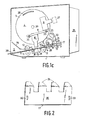
- fig 1 is a side view of an apparatus according to the invention having one side wall removed in a write position, fig 1a, an intermediate position, fig 1b, and a read position, fig 1c, and fig 2 is a perspektive view showing an example of a guide slide suitable to be included in the apparatus according to the invention.
- the apparatus shown in fig 1 for recording and reading comprises a housing 1 having an input/output opening 2.
- a transport path 3 starts from the input/output opening and runs to the rear part of the apparatus.
- Above the transport path 3 there is provided a not in more detail shown cradle 4.
- the cradle consists in the indicated embodiment of two parallel end plates provided with teeth, one end plate 5 being shown between which two rods 34, 35 are attached.
- a support plate 38 which like the rods 34, 35 is attached between the end plates of the cradle, contributs in cooperation with the rods to a solid cradle 4.
- the cradle is born in bearing points 39 in the center of the end plate.
- a carriage 8 supporting one or several heads is running along the rods 34, 35.
- One of the shown heads 9 is a printing head, while the other head 10 is an optical read head (OCR).
- OCR optical read head
- the cradle may be rotated between the two outermost positions which are shown in fig 1a and 1c.
- the printing head 9 is in a write position for documents fed in through the front in fig 1a, while the optical read head 10 is in read position for documents fed in through the front in fig 1c.
- the means consist of a front drive roll 11 in cooperation with a front pressure roll 12 and a rear drive roll 13 also in cooperation with a rear pressure roll 14.
- the drive rolls 11 and 13 are driven by means of a not shown drive motor in a conventional way.
- the front and rear pressure rolls are for the sake of simplicity shown as a single roll but both may in practice consist of several essentially coaxially arranged pressure rolls.
- a print bar 15 is mounted between the front and the rear rolls and an interaction region 28 for the head 9 and 10, respectively, and the document 29 is located above the print bar.
- a guide rail 16 in connection with the input/output opening 2 guides the document fed in along the transport path 3 during the initial feeding of the document 29.
- a guide slide 17 takes over the guiding along the transport path 3 during the continued feeding in of the document.
- the slide is displacable above the interaction region 28 situated above the print bar 15.
- the displacement of the guide slide 17 is obtained by means of a, not shown, drive motor which is coupled to a shaft 18.
- a circular cylindric body 19 is excentrically mounted on the shaft 18.
- a ring 20 rests slidably against the circular cylindric body 19 and has a projection 21 in articulated connection with an arm 22.
- One end of the arm 23 is pivotally born while the other end 24 engages with the guide slide 17 by means of an opening 33 in fig 2.
- the shaft 18 furthermore supports a gear wheel 26 which is in cooperation with one of the plates 5 provided with teeth of the cradle 4.
- the guide slide is moved between a first end position shown in fig 1b and a second end position shown in fig 1a and 1c.
- the cradle 4 is rotated such an angle that the print head 9 is moved away from the interaction region 28 at the same time as the read head 10 comes into position in the interaction region.
- the print head 9, as indicated in fig 1 may be arranged to cooperate with one further print bar 27 in another write position.
- the apparatus When a document is introduced into the input/output opening 2 by an operator, the apparatus ensures that the cradle 4 and the guide slide 17 is in the position shown in fig 1b. This is done by rotation of the drive motor driven shaft 18.
- the gear wheel 26 fixed to the shaft 18 thereby by means of its gear coupling transfers a rotation movement to the end plate 5 of the cradle 4.
- the shaft 18 transfers a translation movement to the guide slide 17 via the circular cylindric body 19, the ring 20 having the projection 21, and the arm 22 pivotally born in one of its ends.
- the apparatus may obtain information that a document 29 is fed in in several different ways.
- One possibility is that the operator supplies this information.
- Another possibility is that the apparatus in optical or another way detects the document and not until the cradle 4 and the guide slide 17 have occupied the intermediate position shown in fig 1b opens the transport path 3 by lowering stop pins 30 provided in the transport path.
- the upper front roll 12 When the stop pins are lowered, the upper front roll 12 is lowered against the front feed roll 11 and the document 29 is grapped and fed further on into the apparatus by the front rolls. The document is prevented to deviate from the transport path 3 by means of the guide slide 17.
- the upper rear roll When the document 29 has past into the space between the rear rolls, the upper rear roll may be lowered to grip and feed in the document further at the same time as the driving from the front drive rolls may be disengaged or driven in parallel with the rear rolls.
- the cradle 4 In dependence on the instructions applied to the apparatus, the cradle 4 either assumes the position shown in fig 1a for printing or the position shown in fig 1c for reading.
- the rotational movement of the heads 9, 10 as well as the translation movement of the guide slide 17 are obtained as before by rotating the shaft 18. Clockwise rotation of the shaft results in a change over to the read position while a counter clockwise rotation results in a change over to the write position for the shown embodiment.
- the interaction region 28 above the print bar 15 is now uncovered and writing or reading may take place in this interaction region.
- the position of the document 29 relative to the position of the head in action is changed by rotating the rear roll pair and/or the front roll pair.
- the driving of the feed rolls 11 and 13, respectively is reversed and the document 29 follows the transport path 3 in a direction towards the input/output opening and is fed out through the same.
- the cradle 4 and the guide slide 17 may be repositioned into the intermediate position to cover the interaction region before the document is fed out. In many applications this is not neccessary but the guide slide may be allowed to remain in the second position shown in fig 1a or 1c.
- the guide slide 17 comprises a plate 36 and a number of bent lugs 31 along one of its long sides, the long side of which is intended to be brought into and above the interaction region 28.
- the space between the lugs 31 is adapted to be able to accommodate the rear pressure roll 14 when the guide slide 17 is brought into and above the interaction region.
- At each short side of the guide slide there is an opening 32 and 33, respectively, for engagement with the end 24 of the arm 22.
Landscapes
- Facsimiles In General (AREA)
- Inspection Of Paper Currency And Valuable Securities (AREA)
- Feeding Of Articles By Means Other Than Belts Or Rollers (AREA)
- Facsimile Scanning Arrangements (AREA)
Abstract
The invention relates to an apparatus for recording information on a document (29) or reading information from the same, and in particular a printer. A head (9 or 10) records information on or reads information from a document (29) transportable along a transport path (3). In order to guide the document (29) along the transport path (3) there are guide means (16, 17). Constructions known until now have the disadvantages that the space in connection to the interaction region (28) for the head (9 or 10) and the document (29) has no guide means for the document. In the case of documents which are difficult to handle, for example, bank books fed in from aside, there is a great risk that the document fed in deviates from the transport path (3). According to the invention this is avoided by the fact that the guide means comprise a displacable guide slide (17) which is displacable into and above the interaction region (28) for the head and the document to essentially bridge over this region during the feeding in and/or feeding out of the document.
Description
- The present invention relates to an apparatus for recording information on a document and/or reading information from the same, comprising a recording and/or reading head for cooperation with the document in an interaction region, a transport path for the document starting from an input/output opening in the apparatus, means for driving the document along the transport path, and means for guiding the document. Apparatus of this kind are inter alia suitable as printers and are used for example for recording and/or reading information on or from the document, respectively, such as paper sheets, books, booklets, bank books and similar documents.
- A printer according to the preamble is previously known from, for example, SE B 8401146-9. The document is fed in through and input/output opening along a transport path. In the transport path and in connection with the print bar of the printer there is an interaction region in which the head cooperates with the document. On both sides of the interaction region there are means in the shape of a drive roll and a pressure roll to drive the document. Inside the inner pair of a drive roll and a pressure roll there are means in the shape of a guide rail to guide the document. In the above mentioned publication it is further more indicated that the printing head of the apparatus may be constructed to print at several stations. In what way this is carried out is not shown but may, for example, be obtained by rotating the head in correspondence with the subject matter shown in SE B 7604415-5. In this case the head is rotatable between two print stations around a shaft parallel to the movement direction of the head.
- A drawback in the prior art printer is that the document fed in does not get any guidance in the interaction region above the print bar or in its vicinity. Documents which are particularly difficult to handle, such as for example bank books having spreading paper sheets and fed in from aside, easily deviates from the transport path and may be damaged or damage the apparatus at the same time as any recording or reading is not possible to carry out during the input and output process. The operator is forced to new attempts with relatively small chances to succeed.
- The object of the invention is to obtain an apparatus operating safely even when recording and/or reading information in documents which are difficult to handle. This is obtained by improving the guidance of the document under the input and possibly even under the output. When the document is fed in and/or fed out, it is ensured that a displacable guide slide is displaced above the interaction region to substantially bridge-over this region. Spreading paper sheets in a bank book are thereby prevented to deflect from the transport path and are as intended guided further on along this path. When recording and/or reading the guide slide is displaced away from the interaction region along the transport path to leave the interaction region open for the head. To obtain a safe operation even when the documents are difficult to handle, the apparatus according to the invention is characterized in that the means for guiding the document comprise a guide slide displacable along the transport path, the guide slide of which during the input and/or output of the document past the interaction region is displaced to a first position to essentially brige over the interaction region, the guide slide during the recording and/or reading of the head being displaced to a second position to lay the interaction region bare.
- According to a favourable embodiment of the invention, the guide slide consists of an essentially flat plate having a number of bent lugs along the side edge adjacent to the interaction region. The space between the lugs is adapted to accommodate drive means in the shape of drive and pressure rolls when the guide slide is in its first position in which the guide slide bridges over the interaction region.
- According to another favourable embodiment of the apparatus according to the invention, in which the head is rotatable between two or more positions around an axis parallel to the movement direction of the head, the apparatus is characterized in that the displacement movement of the guide slide is transferred from a drive common for the rotation of the head and the displacement of the guide slide. In this embodiment there is no need for a separate driving of the guide slide, but a driving present for the rotation of the head is used. This results in that the cost for the components is reduced simuntaneously as the embodiment admits a compact construction.
- An advantageously constructed embodiment of the apparatus having a common driving of the rotation of the head and the displacement of the guide slide and in which the rotation of the head is obtained by means of a cradle supporting the head is characterized in that the common driving of the head and the guide slide is obtained from a shaft driven by a motor, the rotation of the shaft being transferred to the head by means of a gear coupling to the cradle supporting the head and to a translation movement of the guide slide by means of a circular cylindric body provided excentrically on the shaft, on the envelope surface of which is rotatably resting a circular cylindric ring having a projection which is in an articulated connection with an arm pivotally attached in one end, the other end of which engaging the guide slide.
- Advantageously the coupling of the motordriven shaft to the cradle and the guide slide is doubled. According to a further favourable embodiment of the invention the apparatus is therefore characterized in that the transfer of the rotation of the motor driven shaft to the cradle and guide slide is doubled in that a transfer to the cradle is provided in each end of the cradle and a transfer to the guide slide is provided in each of the side edges of the guide slide parallel to the displacement direction of the guide slide. These and other aspects of the invention will be apparent from and elucidated with refrence to the embodiment described hereinafter.
- The invention will now be described in more detail whith reference to the accompanying drawings, in which fig 1 is a side view of an apparatus according to the invention having one side wall removed in a write position, fig 1a, an intermediate position, fig 1b, and a read position, fig 1c, and fig 2 is a perspektive view showing an example of a guide slide suitable to be included in the apparatus according to the invention.
- The apparatus shown in fig 1 for recording and reading comprises a
housing 1 having an input/output opening 2. Atransport path 3 starts from the input/output opening and runs to the rear part of the apparatus. Above thetransport path 3 there is provided a not in more detail showncradle 4. The cradle consists in the indicated embodiment of two parallel end plates provided with teeth, oneend plate 5 being shown between which tworods support plate 38, which like therods solid cradle 4. The cradle is born inbearing points 39 in the center of the end plate. Acarriage 8 supporting one or several heads is running along therods heads 9 is a printing head, while theother head 10 is an optical read head (OCR). The cradle may be rotated between the two outermost positions which are shown in fig 1a and 1c. Theprinting head 9 is in a write position for documents fed in through the front in fig 1a, while theoptical read head 10 is in read position for documents fed in through the front in fig 1c. In the rear section of the apparatus there is aspace 25 for electronics needed for the controlling and driving of the apparatus. - Along the
transport path 3 there are means provided to driveadocument 29. The means consist of afront drive roll 11 in cooperation with afront pressure roll 12 and arear drive roll 13 also in cooperation with arear pressure roll 14. Thedrive rolls print bar 15 is mounted between the front and the rear rolls and aninteraction region 28 for thehead document 29 is located above the print bar. Aguide rail 16 in connection with the input/output opening 2 guides the document fed in along thetransport path 3 during the initial feeding of thedocument 29. Aguide slide 17 takes over the guiding along thetransport path 3 during the continued feeding in of the document. In order to prevent that the document fed in deviates from thetransport path 3 during its continued feeding in, the slide is displacable above theinteraction region 28 situated above theprint bar 15. The displacement of theguide slide 17 is obtained by means of a, not shown, drive motor which is coupled to ashaft 18. A circularcylindric body 19 is excentrically mounted on theshaft 18. Aring 20 rests slidably against the circularcylindric body 19 and has aprojection 21 in articulated connection with anarm 22. One end of thearm 23 is pivotally born while theother end 24 engages with theguide slide 17 by means of an opening 33 in fig 2. - The
shaft 18 furthermore supports agear wheel 26 which is in cooperation with one of theplates 5 provided with teeth of thecradle 4. By rotating theshaft 18, the guide slide is moved between a first end position shown in fig 1b and a second end position shown in fig 1a and 1c. Simultaneously with the movement of the guide slide from the second end position according to fig 1a to the second position according to fig 1c, thecradle 4 is rotated such an angle that theprint head 9 is moved away from theinteraction region 28 at the same time as theread head 10 comes into position in the interaction region. In this position theprint head 9, as indicated in fig 1, may be arranged to cooperate with onefurther print bar 27 in another write position. In this other write position, for example, printing may take place on a receipt and/or journal strip. One transfer of the rotation of theshaft 18 through thecradle 4 and theguide slide 17 has only been described above. For a stable and operation safe transfer of the rotation of the shaft, the apparatus normally is provided with double transfers to thecradle 4 and theguide slide 17. Thereby a transfer is provided at each end of thecradle 4 and theguideslide 17, respectively. - Below the input and output process for a
document 29 will be described in more detail step by step with reference to fig 1. - When a document is introduced into the input/
output opening 2 by an operator, the apparatus ensures that thecradle 4 and theguide slide 17 is in the position shown in fig 1b. This is done by rotation of the drive motor drivenshaft 18. Thegear wheel 26 fixed to theshaft 18 thereby by means of its gear coupling transfers a rotation movement to theend plate 5 of thecradle 4. At the same time theshaft 18 transfers a translation movement to theguide slide 17 via the circularcylindric body 19, thering 20 having theprojection 21, and thearm 22 pivotally born in one of its ends. - The apparatus may obtain information that a
document 29 is fed in in several different ways. One possibility is that the operator supplies this information. Another possibility is that the apparatus in optical or another way detects the document and not until thecradle 4 and theguide slide 17 have occupied the intermediate position shown in fig 1b opens thetransport path 3 by lowering stop pins 30 provided in the transport path. - When the stop pins are lowered, the
upper front roll 12 is lowered against thefront feed roll 11 and thedocument 29 is grapped and fed further on into the apparatus by the front rolls. The document is prevented to deviate from thetransport path 3 by means of theguide slide 17. When thedocument 29 has past into the space between the rear rolls, the upper rear roll may be lowered to grip and feed in the document further at the same time as the driving from the front drive rolls may be disengaged or driven in parallel with the rear rolls. - In dependence on the instructions applied to the apparatus, the
cradle 4 either assumes the position shown in fig 1a for printing or the position shown in fig 1c for reading. The rotational movement of theheads guide slide 17 are obtained as before by rotating theshaft 18. Clockwise rotation of the shaft results in a change over to the read position while a counter clockwise rotation results in a change over to the write position for the shown embodiment. Theinteraction region 28 above theprint bar 15 is now uncovered and writing or reading may take place in this interaction region. The position of thedocument 29 relative to the position of the head in action is changed by rotating the rear roll pair and/or the front roll pair. - When the
document 29 is ready to be fed out the driving of the feed rolls 11 and 13, respectively, is reversed and thedocument 29 follows thetransport path 3 in a direction towards the input/output opening and is fed out through the same. According to one embodiment of thecradle 4 and theguide slide 17 may be repositioned into the intermediate position to cover the interaction region before the document is fed out. In many applications this is not neccessary but the guide slide may be allowed to remain in the second position shown in fig 1a or 1c. - A simple embodiment of the
guide slide 17 is shown in fig 2. Theguide slide 17 comprises aplate 36 and a number ofbent lugs 31 along one of its long sides, the long side of which is intended to be brought into and above theinteraction region 28. The space between thelugs 31 is adapted to be able to accommodate therear pressure roll 14 when theguide slide 17 is brought into and above the interaction region. At each short side of the guide slide there is anopening end 24 of thearm 22.
Claims (5)
- An apparatus for recording information on a document and/or reading information from the same, comprising a recording and/or reading head for cooperation with the document in an interaction region, a transport path for the document starting from an input/output opening in the apparatus, means for driving the document along the transport path, and means for guiding the document, characterized in that the means for guiding the document comprise a guide slide displacable along the transport path, the guide slide of which during the input and/or output of the document past the interaction region is displaced to a first position to essentially bridge-over the interaction region, the guide slide during the recording and/or reading of the head being displaced to a second positon to lay the interaction region bare.
- An apparatus as claimed in claim 1, characterized in that the guide slide consists of an essentially flat plate having a number of bent lugs along the side edge adjacent to the interaction region.
- An apparatus as claimed in any of the claims 1 or 2, in which the head is rotatable between two or more positions around an axis parallel to the movement direction of the head, characterized in that the displacement movement of the guide slide is transferred from a drive common for the rotation of the head and the displacement of the guide slide.
- An apparatus as claimed in claim 3, in which the rotation of the head is obtained by means of a cradle supporting the head, characterized in that the common driving of the head and the guide slide is obtained from a shaft driven by a motor, the rotation of the shaft being transferred to the head by means of a gear coupling to the cradle supporting the head and to a translation movement of the guide slide by means of a circular cylindric body provided excentrically on the shaft, on the envelope surface of which is rotatably resting a circular cylindric ring having a projection which is in an articulated connection with an arm pivotally attached in one end, the other end of which engaging the guide slide.
- An apparatus as claimed in claim 4, characterized in that the transfer of the rotation of the motor driven shaft to the cradle and the guide slide is doubled in that a transfer to the cradle is provided in each end of the cradle and a transfer to the guide slide is provided in each of the side edges of the guide slide parallel to the displacement direction of the guide slide.
Applications Claiming Priority (2)
| Application Number | Priority Date | Filing Date | Title |
|---|---|---|---|
| SE9000475A SE465664B (en) | 1990-02-09 | 1990-02-09 | DEVICE FOR RECORDING AND / OR READING INFORMATION |
| SE9000475 | 1990-02-09 |
Publications (1)
| Publication Number | Publication Date |
|---|---|
| EP0441448A1 true EP0441448A1 (en) | 1991-08-14 |
Family
ID=20378514
Family Applications (1)
| Application Number | Title | Priority Date | Filing Date |
|---|---|---|---|
| EP91200241A Withdrawn EP0441448A1 (en) | 1990-02-09 | 1991-02-06 | Apparatus for recording and/or reading information |
Country Status (4)
| Country | Link |
|---|---|
| US (1) | US5161905A (en) |
| EP (1) | EP0441448A1 (en) |
| JP (1) | JP2804634B2 (en) |
| SE (1) | SE465664B (en) |
Cited By (2)
| Publication number | Priority date | Publication date | Assignee | Title |
|---|---|---|---|---|
| EP0729842A3 (en) * | 1995-02-28 | 1998-07-15 | Hewlett-Packard Company | Media handling in an ink-jet printer |
| US6360657B1 (en) | 1998-08-31 | 2002-03-26 | Seiko Precision, Inc. | Printer |
Families Citing this family (5)
| Publication number | Priority date | Publication date | Assignee | Title |
|---|---|---|---|---|
| US5265966A (en) * | 1993-03-05 | 1993-11-30 | Rimage Corporation | Printer linkage |
| JP3245302B2 (en) * | 1993-07-22 | 2002-01-15 | キヤノン株式会社 | Sheet member conveying device and information processing device using the same |
| US5370465A (en) * | 1993-12-03 | 1994-12-06 | Banker; Robert L. | Method and apparatus for printing traffic citations |
| EP0876923B1 (en) * | 1997-05-08 | 2002-02-06 | Seiko Epson Corporation | Printer with a movable paper guide mechanism and method of setting recording paper in such printer |
| US6089773A (en) * | 1997-12-12 | 2000-07-18 | Lexmark International, Inc. | Print media feed system for an ink jet printer |
Citations (1)
| Publication number | Priority date | Publication date | Assignee | Title |
|---|---|---|---|---|
| WO1984000324A1 (en) * | 1982-07-08 | 1984-02-02 | Konishiroku Photo Ind | Sheet-feeding device for recorder |
Family Cites Families (11)
| Publication number | Priority date | Publication date | Assignee | Title |
|---|---|---|---|---|
| US4164376A (en) * | 1977-12-15 | 1979-08-14 | Dataproducts Corporation | Multiple path paper feed system for a printer |
| JPS5820498A (en) * | 1981-07-31 | 1983-02-05 | 株式会社東芝 | Page turning-over device for booklets |
| JPS5820497A (en) * | 1981-07-31 | 1983-02-05 | 株式会社東芝 | Printer |
| JPS5941286A (en) * | 1982-09-02 | 1984-03-07 | Tokyo Electric Co Ltd | printer paper guide device |
| JPS5967072A (en) * | 1982-10-09 | 1984-04-16 | Ricoh Co Ltd | Paper feeder |
| JPS6123357A (en) * | 1984-07-12 | 1986-01-31 | Nec Corp | Semiconductor integrated circuit |
| JPS61143162A (en) * | 1984-12-18 | 1986-06-30 | Ricoh Co Ltd | Paper guide apparatus in printer |
| JPS61120776A (en) * | 1984-11-16 | 1986-06-07 | Nec Corp | Printer of slips with magnetic stripes |
| JPS62294572A (en) * | 1986-06-16 | 1987-12-22 | Hitachi Ltd | printer |
| JPH07390B2 (en) * | 1986-09-09 | 1995-01-11 | 株式会社日立製作所 | Print media guide device |
| DE3818167A1 (en) * | 1988-05-26 | 1989-11-30 | Mannesmann Ag | DEVICE FOR THE TRANSPORT OF RECORD CARRIERS IN OFFICE MACHINES, ESPECIALLY FOR RECEIPT IN RECEIPT PROCESSING DEVICES |
-
1990
- 1990-02-09 SE SE9000475A patent/SE465664B/en not_active IP Right Cessation
-
1991
- 1991-02-06 EP EP91200241A patent/EP0441448A1/en not_active Withdrawn
- 1991-02-11 US US07/653,831 patent/US5161905A/en not_active Expired - Lifetime
- 1991-02-12 JP JP3039047A patent/JP2804634B2/en not_active Expired - Fee Related
Patent Citations (1)
| Publication number | Priority date | Publication date | Assignee | Title |
|---|---|---|---|---|
| WO1984000324A1 (en) * | 1982-07-08 | 1984-02-02 | Konishiroku Photo Ind | Sheet-feeding device for recorder |
Non-Patent Citations (3)
| Title |
|---|
| IBM Techinal Disclosure Bulletin Vol. 32 No 8A page 244 January 1990 * see figur 1 * * |
| PATENT ABSTRACTS OF JAPAN Vol 11, No 78, M-570 Abstract of JP,A, 61-233571 * see figure 1 * * |
| PATENT ABSTRACTS OF JAPAN Vol. 8 No 143, M-306 Abstracts of JP,A, 59-41286 * see figure 1 * * |
Cited By (2)
| Publication number | Priority date | Publication date | Assignee | Title |
|---|---|---|---|---|
| EP0729842A3 (en) * | 1995-02-28 | 1998-07-15 | Hewlett-Packard Company | Media handling in an ink-jet printer |
| US6360657B1 (en) | 1998-08-31 | 2002-03-26 | Seiko Precision, Inc. | Printer |
Also Published As
| Publication number | Publication date |
|---|---|
| SE9000475L (en) | 1991-08-10 |
| SE9000475D0 (en) | 1990-02-09 |
| US5161905A (en) | 1992-11-10 |
| JPH04213531A (en) | 1992-08-04 |
| SE465664B (en) | 1991-10-14 |
| JP2804634B2 (en) | 1998-09-30 |
Similar Documents
| Publication | Publication Date | Title |
|---|---|---|
| US5060877A (en) | Automatic paper feed apparatus | |
| US7258500B2 (en) | Media processing apparatus and scanner unit | |
| CN101239539B (en) | Printer equipped with cutter mechanism | |
| US5161905A (en) | Apparatus for recording and/or reading information | |
| US5040908A (en) | Passbook printer with line find mechanism | |
| US5330274A (en) | Printing device having at least two printing stations separated spatially from one another | |
| US4995184A (en) | Passbook page turning mechanism | |
| US6728012B2 (en) | Multifunction terminal | |
| EP0026890A2 (en) | Paper drive mechanism for a printer | |
| US6695427B2 (en) | Multifunction device and control method for the same | |
| US6012862A (en) | Ink-jet printing apparatus having paper feed structure and control | |
| CN1130669C (en) | Additional apparatus for passbook management and operating method thereof | |
| JPS63252769A (en) | Paper conveyor in business equipement such as printer | |
| US3965292A (en) | Paper handling apparatus for facsimile receiver | |
| JPH11106096A (en) | Printer | |
| CA1292484C (en) | Compact printer with cassette-drawer sheet feeder | |
| JP3131734B1 (en) | Printing mechanism of printing apparatus and printing method | |
| JPS6141436B2 (en) | ||
| JPS63199668A (en) | printing device | |
| JPS62104776A (en) | Recording apparatus | |
| JPS5828119B2 (en) | Automatic passbook turning device | |
| JPH0466426B2 (en) | ||
| JPS6116636B2 (en) | ||
| JPS6174448A (en) | Scanner for tele-copying | |
| JPH0781819A (en) | Paper transport device |
Legal Events
| Date | Code | Title | Description |
|---|---|---|---|
| PUAI | Public reference made under article 153(3) epc to a published international application that has entered the european phase |
Free format text: ORIGINAL CODE: 0009012 |
|
| AK | Designated contracting states |
Kind code of ref document: A1 Designated state(s): DE FR GB IT SE |
|
| 17P | Request for examination filed |
Effective date: 19920214 |
|
| RAP1 | Party data changed (applicant data changed or rights of an application transferred) |
Owner name: DIGITAL EQUIPMENT CORPORATION |
|
| 17Q | First examination report despatched |
Effective date: 19931108 |
|
| STAA | Information on the status of an ep patent application or granted ep patent |
Free format text: STATUS: THE APPLICATION IS DEEMED TO BE WITHDRAWN |
|
| 18D | Application deemed to be withdrawn |
Effective date: 19940519 |