EP0441466A2 - Corps creux à double paroi ayant une couche intermédiaire et son procédé de fabrication - Google Patents
Corps creux à double paroi ayant une couche intermédiaire et son procédé de fabrication Download PDFInfo
- Publication number
- EP0441466A2 EP0441466A2 EP91250031A EP91250031A EP0441466A2 EP 0441466 A2 EP0441466 A2 EP 0441466A2 EP 91250031 A EP91250031 A EP 91250031A EP 91250031 A EP91250031 A EP 91250031A EP 0441466 A2 EP0441466 A2 EP 0441466A2
- Authority
- EP
- European Patent Office
- Prior art keywords
- hollow body
- intermediate layer
- double
- inner hollow
- wall
- Prior art date
- Legal status (The legal status is an assumption and is not a legal conclusion. Google has not performed a legal analysis and makes no representation as to the accuracy of the status listed.)
- Withdrawn
Links
Images
Classifications
-
- F—MECHANICAL ENGINEERING; LIGHTING; HEATING; WEAPONS; BLASTING
- F01—MACHINES OR ENGINES IN GENERAL; ENGINE PLANTS IN GENERAL; STEAM ENGINES
- F01N—GAS-FLOW SILENCERS OR EXHAUST APPARATUS FOR MACHINES OR ENGINES IN GENERAL; GAS-FLOW SILENCERS OR EXHAUST APPARATUS FOR INTERNAL-COMBUSTION ENGINES
- F01N13/00—Exhaust or silencing apparatus characterised by constructional features
- F01N13/18—Construction facilitating manufacture, assembly, or disassembly
- F01N13/1883—Construction facilitating manufacture, assembly, or disassembly manufactured by hydroforming
-
- F—MECHANICAL ENGINEERING; LIGHTING; HEATING; WEAPONS; BLASTING
- F01—MACHINES OR ENGINES IN GENERAL; ENGINE PLANTS IN GENERAL; STEAM ENGINES
- F01N—GAS-FLOW SILENCERS OR EXHAUST APPARATUS FOR MACHINES OR ENGINES IN GENERAL; GAS-FLOW SILENCERS OR EXHAUST APPARATUS FOR INTERNAL-COMBUSTION ENGINES
- F01N13/00—Exhaust or silencing apparatus characterised by constructional features
- F01N13/14—Exhaust or silencing apparatus characterised by constructional features having thermal insulation
-
- F—MECHANICAL ENGINEERING; LIGHTING; HEATING; WEAPONS; BLASTING
- F01—MACHINES OR ENGINES IN GENERAL; ENGINE PLANTS IN GENERAL; STEAM ENGINES
- F01N—GAS-FLOW SILENCERS OR EXHAUST APPARATUS FOR MACHINES OR ENGINES IN GENERAL; GAS-FLOW SILENCERS OR EXHAUST APPARATUS FOR INTERNAL-COMBUSTION ENGINES
- F01N13/00—Exhaust or silencing apparatus characterised by constructional features
- F01N13/14—Exhaust or silencing apparatus characterised by constructional features having thermal insulation
- F01N13/141—Double-walled exhaust pipes or housings
-
- F—MECHANICAL ENGINEERING; LIGHTING; HEATING; WEAPONS; BLASTING
- F01—MACHINES OR ENGINES IN GENERAL; ENGINE PLANTS IN GENERAL; STEAM ENGINES
- F01N—GAS-FLOW SILENCERS OR EXHAUST APPARATUS FOR MACHINES OR ENGINES IN GENERAL; GAS-FLOW SILENCERS OR EXHAUST APPARATUS FOR INTERNAL-COMBUSTION ENGINES
- F01N13/00—Exhaust or silencing apparatus characterised by constructional features
- F01N13/16—Selection of particular materials
-
- F—MECHANICAL ENGINEERING; LIGHTING; HEATING; WEAPONS; BLASTING
- F16—ENGINEERING ELEMENTS AND UNITS; GENERAL MEASURES FOR PRODUCING AND MAINTAINING EFFECTIVE FUNCTIONING OF MACHINES OR INSTALLATIONS; THERMAL INSULATION IN GENERAL
- F16L—PIPES; JOINTS OR FITTINGS FOR PIPES; SUPPORTS FOR PIPES, CABLES OR PROTECTIVE TUBING; MEANS FOR THERMAL INSULATION IN GENERAL
- F16L59/00—Thermal insulation in general
- F16L59/02—Shape or form of insulating materials, with or without coverings integral with the insulating materials
- F16L59/029—Shape or form of insulating materials, with or without coverings integral with the insulating materials layered
-
- F—MECHANICAL ENGINEERING; LIGHTING; HEATING; WEAPONS; BLASTING
- F01—MACHINES OR ENGINES IN GENERAL; ENGINE PLANTS IN GENERAL; STEAM ENGINES
- F01N—GAS-FLOW SILENCERS OR EXHAUST APPARATUS FOR MACHINES OR ENGINES IN GENERAL; GAS-FLOW SILENCERS OR EXHAUST APPARATUS FOR INTERNAL-COMBUSTION ENGINES
- F01N13/00—Exhaust or silencing apparatus characterised by constructional features
- F01N13/08—Other arrangements or adaptations of exhaust conduits
-
- F—MECHANICAL ENGINEERING; LIGHTING; HEATING; WEAPONS; BLASTING
- F01—MACHINES OR ENGINES IN GENERAL; ENGINE PLANTS IN GENERAL; STEAM ENGINES
- F01N—GAS-FLOW SILENCERS OR EXHAUST APPARATUS FOR MACHINES OR ENGINES IN GENERAL; GAS-FLOW SILENCERS OR EXHAUST APPARATUS FOR INTERNAL-COMBUSTION ENGINES
- F01N2310/00—Selection of sound absorbing or insulating material
Definitions
- the invention relates to a double-walled hollow body according to the preamble of claim 1 and a method for producing the same.
- a generic double wall hollow body is known from DE-PS 37 12 193. It consists of an inner tube and an outer tube, which are arranged at a distance so that they form an annular space in which ceramic powder is arranged in the sense of sound insulation.
- the outer tube consists of a less temperature-resistant steel and is connected to the inner tube in a gastight manner at its retracted ends.
- a disadvantage of this proposal is the required filling technique of the ceramic powder, which is an obstacle to the mass production of large quantities.
- the proposed double wall tube is also not suitable as a construction element for the transmission of forces and torques.
- German Offenlegungsschrift 23 55 126 which also has an inner pipe and an outer pipe with an insulating layer in between.
- the insulating material preferably consists of aluminum silicate ceramic. This double wall pipe is also not suitable for transmitting larger forces or torques.
- the object of the invention is to provide an improved double-walled hollow body which is suitable as a sound-absorbing structural element in motor vehicle construction for mass production and can transmit greater forces or torques.
- the double-wall hollow body according to the invention is characterized in that the interlayer made of the non-metallic, sound-absorbing material separates the inner from the outer hollow body over the entire circumference by a force-locking connection of the inner with the outer hollow body.
- the cross-sectional profile of the inner or outer hollow body can be arbitrary and is primarily dependent on the respective intended use of such a double-wall hollow body.
- the cross section is preferably circular, since the production of such hollow bodies is inexpensive and the production of a double wall tube is particularly simple.
- the double-walled hollow body according to the invention has the advantage that the elimination of the weld seam passing through the intermediate layer gives more freedom in the selection of the best possible insulating material, since there is no need to consider welding compatibility.
- the non-positive connection forms a continuous long section, which is not interrupted by a metallic bridge and thus the sound insulation is particularly effective.
- the intermediate layer is first applied to the inner hollow body and then this is inserted into the outer hollow body and finally at least one of the two hollow bodies is plastically deformed to such an extent that it non-positively engages with the other hollow body is coming.
- the type of application of the intermediate layer to the inner hollow body can take place in various ways. One of the possibilities is to pull the intermediate layer in the form of a tube onto the inner hollow body. The use of a flat product for the intermediate layer and the wrapping of the inner hollow body in the intermediate layer pre-cut to size is more cost-effective. Depending on the type of insulation, it can be connected to the inner hollow body using heat or an adhesive.
- the expansion required after inserting the inner hollow body provided with the intermediate layer into the outer hollow body having a larger internal dimension can be hydraulic or mechanical, Z. B. by pushing through a widening inner tool, an additional widening being required in the region of the liner-free section. Hydraulic expansion is always preferable if more than one section is to be free of intermediate layers or if this section is not at the end of the hollow body.
- Another possibility of applying the intermediate layer consists in winding a band of the insulating material onto the inner hollow body, be it in one or more layers.
- a readily plastically deformable material is chosen as the material for the inner or outer hollow body, both hollow bodies being made of the same material for cost reasons.
- the intermediate layer used should be inexpensive and particularly suitable with regard to the application to the inner hollow body and have a good sound insulation value. These conditions are e.g. B. met to a high degree by a bitumen film.
- the method described is advantageously used to produce a sound-insulated propeller shaft which has an intermediate layer-free section at each end.
- the cardan shaft is one of the elements that emit a large sound spectrum.
- the proposed double wall tube is therefore particularly suitable for remedying this without the function of the cardan shaft having to be restricted in any way.
- the double wall tube has the advantage of saving weight compared to the previously known forging.
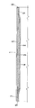
- an embodiment of the double-wall hollow body according to the invention in the form of a double-wall pipe 1 is shown in cross-section. It consists of an inner tube 2, for. B. of steel St. 37, which is coated with a non-metallic, sound-absorbing intermediate layer 3.
- the intermediate layer 3 should consist of bitumen film and have a thickness of, for example, 1 mm.
- the outer surface 4 of the inner tube 2 is provided with an adhesive and then the inner tube 2 has been rolled into the intermediate layer 3 cut to size beforehand.
- the resulting outer diameter of the coated inner tube 2 is, for. B. 1 - 3 mm less than the inner diameter of the outer tube 5 already produced, so that an easy insertion is possible.
- the dimensions of the tubes should be, for example, 2 (50 x 1) mm for the inner tube and 5 (55 x 1) mm for the outer tube.
- the outer tube 5 should also be a steel tube of the same material in this example. The open ends of the double-wall pipe 1 are then closed in a known manner and the inner pipe 2 is widened by a hydraulic method. The expansion process results in a non-positive connection of the inner tube 2 with the outer tube 5 including with the intermediate layer 3.
- the internal pressure can be determined such that only the inner tube 2 flows plastically and the outer tube 5 is not also formed.
- the length of the intermediate layer 3 applied to the inner tube 2 is dimensioned for the example of the cardan shaft in such a way that an intermediate layer-free section 6, 7 is formed at both ends.
- an intermediate layer-free section 6, 7 is formed at both ends.
- the corresponding connection piece also not shown here, can be welded on.
Landscapes
- Engineering & Computer Science (AREA)
- General Engineering & Computer Science (AREA)
- Mechanical Engineering (AREA)
- Chemical & Material Sciences (AREA)
- Combustion & Propulsion (AREA)
- Manufacturing & Machinery (AREA)
- Exhaust Silencers (AREA)
- Laminated Bodies (AREA)
- Shafts, Cranks, Connecting Bars, And Related Bearings (AREA)
Applications Claiming Priority (2)
| Application Number | Priority Date | Filing Date | Title |
|---|---|---|---|
| DE4004072 | 1990-02-08 | ||
| DE4004072A DE4004072C2 (de) | 1990-02-08 | 1990-02-08 | Doppelwandhohlkörper |
Publications (2)
| Publication Number | Publication Date |
|---|---|
| EP0441466A2 true EP0441466A2 (fr) | 1991-08-14 |
| EP0441466A3 EP0441466A3 (en) | 1991-12-18 |
Family
ID=6399854
Family Applications (1)
| Application Number | Title | Priority Date | Filing Date |
|---|---|---|---|
| EP19910250031 Withdrawn EP0441466A3 (en) | 1990-02-08 | 1991-02-06 | Double-walled hollow body having intermediate layer and method of manufacturing the same |
Country Status (3)
| Country | Link |
|---|---|
| US (1) | US5260522A (fr) |
| EP (1) | EP0441466A3 (fr) |
| DE (1) | DE4004072C2 (fr) |
Cited By (3)
| Publication number | Priority date | Publication date | Assignee | Title |
|---|---|---|---|---|
| EP1464475A1 (fr) * | 2003-04-03 | 2004-10-06 | Ford Global Technologies, Inc., A subsidiary of Ford Motor Company | Panneau sandwich |
| EP2607772A1 (fr) * | 2011-12-19 | 2013-06-26 | Benteler Automobiltechnik GmbH | Conduite de gaz d'échappement isolée pour un moteur à combustion interne |
| DE102006027541B4 (de) * | 2005-09-14 | 2013-12-12 | Tenneco Gmbh | Gehäuse in einer Abgasanlage für Verbrennungsmotoren |
Families Citing this family (10)
| Publication number | Priority date | Publication date | Assignee | Title |
|---|---|---|---|---|
| JP2967390B2 (ja) * | 1994-04-21 | 1999-10-25 | 本田技研工業株式会社 | 消音器及びその製造方法 |
| JPH10512201A (ja) * | 1995-01-13 | 1998-11-24 | ミネソタ・マイニング・アンド・マニュファクチュアリング・カンパニー | 固定具の力の保持が改善された減衰積層板、製造方法及び製造に役立つ新しい工具 |
| DE10106590A1 (de) * | 2001-02-13 | 2002-08-14 | Gillet Heinrich Gmbh | Schalldämpfer |
| DE10201594A1 (de) * | 2002-01-16 | 2003-07-24 | Tower Automotive Hydroforming | Verfahren zur Herstellung doppelwandiger Bauteile, insbesondere doppelwandiger Rohre, sowie dadurch hergestelltes Bauteil |
| US7134964B2 (en) * | 2003-08-20 | 2006-11-14 | Gkn Driveline North America, Inc. | Propeller shaft assembly with stiffening feature |
| US6986713B2 (en) * | 2003-08-20 | 2006-01-17 | Gkn Driveline North America, Inc. | Propeller shaft |
| FR2869950B1 (fr) * | 2004-05-05 | 2007-12-14 | Faurecia Sys Echappement | Conduit de circulation des gaz d'echappement d'un vehicule automobile, et ligne d'echappement associee |
| DE102009052834A1 (de) | 2009-11-13 | 2011-05-19 | Bdd Beteiligungs Gmbh | Thermoisoliertes Doppelmetallrohr |
| DE102016208690A1 (de) | 2016-05-20 | 2017-11-23 | Bayerische Motoren Werke Aktiengesellschaft | Schwingungsgedämpftes Rohr |
| CN111878666B (zh) * | 2020-07-20 | 2021-11-09 | 上海隆振建筑工程股份有限公司 | 一种建筑保温管 |
Family Cites Families (13)
| Publication number | Priority date | Publication date | Assignee | Title |
|---|---|---|---|---|
| DE137116C (fr) * | ||||
| US3415336A (en) * | 1966-11-14 | 1968-12-10 | Arvin Ind Inc | Resonator and method of making it |
| GB1323298A (en) * | 1970-03-10 | 1973-07-11 | Duerr Kkg | Heat insulated pipes |
| US3765506A (en) * | 1972-11-08 | 1973-10-16 | Tenneco Inc | Sound attenuating muffler |
| FR2228189A1 (en) * | 1973-05-04 | 1974-11-29 | Bvs | Method of coverring pipes with insulation - uses internal press. to deform insulation between pipe and envelope |
| BR5701149U (pt) * | 1977-09-16 | 1978-03-07 | P Negrao | Atenuador |
| GB2019529B (en) * | 1978-04-15 | 1982-08-25 | Dunlop Ltd | Resilient shaft couplings |
| US4272971A (en) * | 1979-02-26 | 1981-06-16 | Rockwell International Corporation | Reinforced tubular structure |
| IT1071401B (it) * | 1980-04-24 | 1985-04-10 | Zema S R L | Procedimento per la ricopertura con chiuma e pellicola plastica di tubi metallici,macchina per attuare detto procedimento e prodotto ottenuto |
| DE3404771A1 (de) * | 1984-02-10 | 1985-08-14 | Dr.Ing.H.C. F. Porsche Ag, 7000 Stuttgart | Abgasleitung einer hubkolben-brennkraftmaschine |
| US4860851A (en) * | 1987-01-27 | 1989-08-29 | Raychem Corporation | Dimensionally-recoverable damping article |
| DE3712193A1 (de) * | 1987-04-10 | 1988-10-27 | Leistritz Ag | Emissionsgeschuetztes mantelrohr |
| NL8900869A (nl) * | 1989-04-07 | 1990-11-01 | Johannes Bernardus Engelberts | Voorgespannen geisoleerd buiselement. |
-
1990
- 1990-02-08 DE DE4004072A patent/DE4004072C2/de not_active Expired - Fee Related
-
1991
- 1991-02-06 EP EP19910250031 patent/EP0441466A3/de not_active Withdrawn
- 1991-02-06 US US07/651,197 patent/US5260522A/en not_active Expired - Fee Related
Cited By (3)
| Publication number | Priority date | Publication date | Assignee | Title |
|---|---|---|---|---|
| EP1464475A1 (fr) * | 2003-04-03 | 2004-10-06 | Ford Global Technologies, Inc., A subsidiary of Ford Motor Company | Panneau sandwich |
| DE102006027541B4 (de) * | 2005-09-14 | 2013-12-12 | Tenneco Gmbh | Gehäuse in einer Abgasanlage für Verbrennungsmotoren |
| EP2607772A1 (fr) * | 2011-12-19 | 2013-06-26 | Benteler Automobiltechnik GmbH | Conduite de gaz d'échappement isolée pour un moteur à combustion interne |
Also Published As
| Publication number | Publication date |
|---|---|
| EP0441466A3 (en) | 1991-12-18 |
| DE4004072C2 (de) | 1994-08-25 |
| US5260522A (en) | 1993-11-09 |
| DE4004072A1 (de) | 1991-08-14 |
Similar Documents
| Publication | Publication Date | Title |
|---|---|---|
| DE3007896C2 (de) | Anschlußverbindung für durch Faserkunststoffrohre gebildete Hohlwellen, insbesondere für Kraftfahrzeuge | |
| EP0919703B1 (fr) | Procédé de fabrication d'un collecteur d'échappement isolé par une couche d'air pour un véhicule | |
| DE19654552C2 (de) | Antriebswelle für ein Fahrzeug | |
| EP0737803B1 (fr) | Collecteur d'échappement, en particulier pour un moteur à combustion interne d'un véhicule à moteur, et procédé pour sa fabrication | |
| DE19526769C2 (de) | Verfahren zur Herstellung einer stoßabsorbierenden Lenkwelle | |
| DE3527111A1 (de) | Metallischer, gewickelter abgaskatalysatortraegerkoerper mit geometrisch komplizierter form des querschnitts sowie verfahren, vorrichtung und rohling zu seiner herstellung | |
| DE3020020A1 (de) | Verfahren zur herstellung einer rohrfoermigen, faserverstaerkten zusammengesetzten welle oder verbundwelle - ii | |
| DE4004072C2 (de) | Doppelwandhohlkörper | |
| DE3510091A1 (de) | Antriebswelle, insbesondere fuer kraftfahrzeuge | |
| EP0818615B1 (fr) | Boîtier de catalyseur | |
| DE2164814C2 (de) | Rohrförmiges, aus zwei koaxial zueinander angeordneten gewellten Rohren bestehendes Gebilde | |
| DE69703856T2 (de) | Kupplung für zwei Metallrohre | |
| DE102010014573A1 (de) | Verfahren zur Herstellung eines Fahrzeugschalldämpfers und Fahrzeugschalldämpfer | |
| DE2926357A1 (de) | Auspuffdichtung | |
| DE3327353C2 (de) | Isolierte Abgasleitung für Kraftfahrzeuge sowie Verfahren und Vorrichtung zu deren Herstellung | |
| DE4414710C1 (de) | Gelenkwelle für Kraftfahrzeuge | |
| DE19851492A1 (de) | Verfahren zum Herstellen eines Bauteils mittels Innenhochdruck-Umformen | |
| EP0793030A2 (fr) | Arbre d'entrainement | |
| EP0775027B1 (fr) | Procede de production d'un tube creux | |
| DE19515180C2 (de) | Gebaute Welle zur Kraftübertragung | |
| DE4322902B4 (de) | Vorrichtung zur Herstellung von Wellrohren | |
| DE19857445B4 (de) | Verfahren zur Herstellung eines luftspaltisolierten Abgasrohres | |
| EP0985837B1 (fr) | Arbre, en particulier arbre moteur, bras de guidage, entretoise ou similaire | |
| DE19645227A1 (de) | Rohrförmiges Bauteil, insbesondere für eine Gelenkwelle | |
| EP2148101B1 (fr) | Agencement d'arbres doté d'éléments d'arbres internes et externes mobiles les uns à l'intérieur des autres |
Legal Events
| Date | Code | Title | Description |
|---|---|---|---|
| PUAI | Public reference made under article 153(3) epc to a published international application that has entered the european phase |
Free format text: ORIGINAL CODE: 0009012 |
|
| AK | Designated contracting states |
Kind code of ref document: A2 Designated state(s): DE ES FR GB IT |
|
| PUAL | Search report despatched |
Free format text: ORIGINAL CODE: 0009013 |
|
| AK | Designated contracting states |
Kind code of ref document: A3 Designated state(s): DE ES FR GB IT |
|
| 17P | Request for examination filed |
Effective date: 19911216 |
|
| 17Q | First examination report despatched |
Effective date: 19920720 |
|
| STAA | Information on the status of an ep patent application or granted ep patent |
Free format text: STATUS: THE APPLICATION IS DEEMED TO BE WITHDRAWN |
|
| 18D | Application deemed to be withdrawn |
Effective date: 19940628 |