EP0441525A2 - Mécanisme de sécurité pour une installation frigorifique d'un conteneur de véhicule - Google Patents
Mécanisme de sécurité pour une installation frigorifique d'un conteneur de véhicule Download PDFInfo
- Publication number
- EP0441525A2 EP0441525A2 EP91300714A EP91300714A EP0441525A2 EP 0441525 A2 EP0441525 A2 EP 0441525A2 EP 91300714 A EP91300714 A EP 91300714A EP 91300714 A EP91300714 A EP 91300714A EP 0441525 A2 EP0441525 A2 EP 0441525A2
- Authority
- EP
- European Patent Office
- Prior art keywords
- door
- motor
- safety mechanism
- power source
- alternating current
- Prior art date
- Legal status (The legal status is an assumption and is not a legal conclusion. Google has not performed a legal analysis and makes no representation as to the accuracy of the status listed.)
- Withdrawn
Links
Images

Classifications
-
- B—PERFORMING OPERATIONS; TRANSPORTING
- B60—VEHICLES IN GENERAL
- B60H—ARRANGEMENTS OF HEATING, COOLING, VENTILATING OR OTHER AIR-TREATING DEVICES SPECIALLY ADAPTED FOR PASSENGER OR GOODS SPACES OF VEHICLES
- B60H1/00—Heating, cooling or ventilating devices
- B60H1/32—Cooling devices
- B60H1/3204—Cooling devices using compression
- B60H1/3225—Cooling devices using compression characterised by safety arrangements, e.g. compressor anti-seizure means or by signalling devices
-
- F—MECHANICAL ENGINEERING; LIGHTING; HEATING; WEAPONS; BLASTING
- F25—REFRIGERATION OR COOLING; COMBINED HEATING AND REFRIGERATION SYSTEMS; HEAT PUMP SYSTEMS; MANUFACTURE OR STORAGE OF ICE; LIQUEFACTION SOLIDIFICATION OF GASES
- F25D—REFRIGERATORS; COLD ROOMS; ICE-BOXES; COOLING OR FREEZING APPARATUS NOT OTHERWISE PROVIDED FOR
- F25D29/00—Arrangement or mounting of control or safety devices
- F25D29/003—Arrangement or mounting of control or safety devices for movable devices
-
- H—ELECTRICITY
- H01—ELECTRIC ELEMENTS
- H01R—ELECTRICALLY-CONDUCTIVE CONNECTIONS; STRUCTURAL ASSOCIATIONS OF A PLURALITY OF MUTUALLY-INSULATED ELECTRICAL CONNECTING ELEMENTS; COUPLING DEVICES; CURRENT COLLECTORS
- H01R13/00—Details of coupling devices of the kinds covered by groups H01R12/70 or H01R24/00 - H01R33/00
- H01R13/66—Structural association with built-in electrical component
- H01R13/70—Structural association with built-in electrical component with built-in switch
- H01R13/707—Structural association with built-in electrical component with built-in switch interlocked with contact members or counterpart
-
- H—ELECTRICITY
- H01—ELECTRIC ELEMENTS
- H01R—ELECTRICALLY-CONDUCTIVE CONNECTIONS; STRUCTURAL ASSOCIATIONS OF A PLURALITY OF MUTUALLY-INSULATED ELECTRICAL CONNECTING ELEMENTS; COUPLING DEVICES; CURRENT COLLECTORS
- H01R2201/00—Connectors or connections adapted for particular applications
- H01R2201/26—Connectors or connections adapted for particular applications for vehicles
Definitions
- the present invention relates to a safety mechanism for a refrigerator for a vehicle container, and more particularly to a safety mechanism for safely breaking a main current to a motor operated compressor of the refrigerator mounted on the container.
- Vehicles to which a container with a refrigerator may be separably joined are well known.
- an alternating current generator driven by an engine is provided in the vehicle, a motor operated compressor and an exciting current supplying circuit for the excitation of the alternating current generator are provided in the container, and the refrigerator is driven by electrical power sent to the container from either the alternating current generator or an external power source (for example, a commercial power source).
- an external power source for example, a commercial power source
- a connector is provided to allow the cable connection extending between the vehicle and the container to be broken, and a main current route from the alternating current generator and an exciting current route to the alternating current generator are simultaneously broken by disconnecting the cable connection.
- a safety mechanism for a refrigerator for a vehicle with a container which can prevent a main current to the refrigerator from being directly broken by the operation of opening off a connector, thereby preventing generation of arc and burning of contacts of the connector.
- a safety mechanism for a refrigerator for a vehicle with a container according to the present invention is herein provided.
- the container is joined to the vehicle separably from the vehicle, and the refrigerator is mounted on the container and has a motor-operated compressor for compressing a cooling medium.
- a motor driving current is supplied to the motor-operated compressor through a main current route extending from an alternating current generator provided in the vehicle or an external power source to the motor-operated compressor.
- the main current route has a connector provided in a connection box with a door positioned between the container and the vehicle or the external power source.
- a door switch and a control unit are provided in the mechanism. The door switch is on-off operated depending on the opening and closing operations of the door of the connection box, and the control unit controls the main current route in accordance with the operation of the door switch to its continuity condition when the door is closed and to its break condition when the door is opened.
- the breaking of the main current route may be performed by, for example, stopping the supply of an exciting current to the alternating current generator to stop the generation of a voltage of the generator, stopping the supply of a motor driving current to the motor-operated compressor through a motor control circuit, or controlling both such operations, as shown in the embodiments described later.
- FIG. 1 shows an electrical system of a vehicle 1 with a container 2.
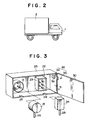
- container 2 is joined to vehicle 1 as shown in FIG. 2, and the container is separated from the vehicle as needed.
- An alternating current generator 3 is provided in vehicle 1, driven by an engine 4 and the generated electrical power is supplied to container 2.
- a refrigerator 5 is mounted on container 2.
- the refrigerator 5 has a motor-operated compressor 6 for compressing a cooling medium, an outdoor heat exchanger 7 condensing the compressed cooling medium, an expansion valve 8 expanding and cooling the cooling medium from the outdoor heat exchanger, an indoor heat exchanger 9 evaporating the cooling medium from the expansion valve and sending a cooled air into the container, and a receiver dryer 10.
- a motor control circuit 11, a power source unit 12 generating an excitation power for alternating current generator 3 and control power for various pieces of equipment, an exciting current supplying circuit 13 supplying an exciting current to the alternating current generator, a centralised control unit 16, and a power source switching device 20 are provided in container 2.
- Centralised control unit 16 controls the operations of motor control circuit 11, exciting current supplying circuit 13 and power source switching device 20 in accordance with the switching condition of an engine key switch 17, the detecting signals sent from sensors (for example, a temperature sensor 19) through an A/D converter (analog/digital converter) 18 and the on-off operation of a door switch 32 described later.
- Power source switching device 20 switches the current route of three phases U, V and W to motor-operated compressor 6 and exciting current supplying circuit 13 to a current route from either alternating current generator 3 or an external power source 40 (for example, a commercial power source), according to the signal from centralised controller 16.
- Engine key switch 17 is connected to a battery 19.
- External power source 40 is connected to the container through a plug 14 and a plug receiver 15 for the external power source.
- Alternating current generator 3 is connected to the container through a connector 22 provided between vehicle 1 and container 2.
- Connector 22 has a connector piece 23 on the container side and a connector piece 24 on the vehicle side. Connector piece 23 and connector piece 24 are free to be connected to and separated from each other.
- Connector 22 can simultaneously connect or disconnect the cables of the three phases U, V and W, which constitute the main current route between alternating current generator 3 and power source switching device 20, and the cables of phases J and K, which constitute the exciting current route between alternating current generator 3 and exciting current supplying circuit 13.
- FIG. 3 illustrates the connection portion shown in FIG. 1.
- a connection box 25 is attached to container 2, and plug 14 and connector piece 23 of connector 22 are fixed in the connection box.
- Plug receiver 15 can be connected to and separated from plug 14, and in the connection state, its cord 26 is led from the lower portion of connection box 25 to the outside through a slot 27 formed on the bottom of the box.
- Connector piece 24, on the vehicle side simultaneously connects or disconnects the cables of the three phases U, V and W of the main current route and the cables of phases J and K of the exciting current route by the operation of connecting it to and separating it from connector piece 23.
- its cord 28 is led from the lower portion of connection box 25 to alternating current generator 3 side through a slot 29 formed on the bottom of the box.
- Connection box 25 has a door 30 which is urged in its closing direction by a spring 31 to normally close the box.
- a door switch 32 is provided in or on connection box 25.
- door switch 32 comprises a switch body 33 having an actuator 34 and a projection 35 actuating the actuator.
- Switch body 33 is attached in connection box 25, and projection 35 is attached on the back surface of door 30.
- projection 35 pushes actuator 34 of switch body 33 and door switch 32 operates so as to be “on”.
- projection 35 separates from actuator 34 of switch body 33 and door switch 32 operates so as to be “off”.
- the on-off signal of door switch 32 is sent to centralised control unit 16.
- Table 1 Table 2 and Table 3 show examples of the control by centralised control unit 16.
- alternating current generator 3 when connector 22 is in the connection condition, engine key switch 17 is "on” and power source switching device 20 switches the main current route to the alternating current generator 3, door 30 of connection box 25 is closed, door switch 32 is "on” and exciting current supplying circuit 13 and motor control circuit 11 are in the ON condition, i.e., continuity condition.
- alternating current generator 3 In this condition, alternating current generator 3 is being driven or started to be driven by engine 4.
- alternating current generator 3 generates a small voltage by its residual magnetism, and thereafter, the alternating current generator generates a required constant voltage by the supply of the exciting current from exciting current supplying circuit 13.
- Motor-operated compressor 6 is driven and refrigerator 5 is operated.
- door switch 32 becomes "off". Since the operation of motor control circuit 11 is stopped, the main current to motor-operated compressor 6 is stopped. Thereafter, when plug 14 and plug receiver 15 are cut off, arc does not occur between their contacts because the main current has already become zero by that time.
- power source switching device 20 is switched depending on the on-off operation of engine key switch 17, instead of this control system, the switching may be controlled according to the operation condition of engine 4 or the voltage output of alternating current generator 3 and external power source 40.
Landscapes
- Engineering & Computer Science (AREA)
- Physics & Mathematics (AREA)
- Thermal Sciences (AREA)
- Mechanical Engineering (AREA)
- Chemical & Material Sciences (AREA)
- Combustion & Propulsion (AREA)
- General Engineering & Computer Science (AREA)
- Devices That Are Associated With Refrigeration Equipment (AREA)
Applications Claiming Priority (2)
| Application Number | Priority Date | Filing Date | Title |
|---|---|---|---|
| JP12554/90 | 1990-02-09 | ||
| JP1255490 | 1990-02-09 |
Publications (2)
| Publication Number | Publication Date |
|---|---|
| EP0441525A2 true EP0441525A2 (fr) | 1991-08-14 |
| EP0441525A3 EP0441525A3 (en) | 1992-06-17 |
Family
ID=31889748
Family Applications (1)
| Application Number | Title | Priority Date | Filing Date |
|---|---|---|---|
| EP19910300714 Withdrawn EP0441525A3 (en) | 1990-02-09 | 1991-01-30 | Safety mechanism for vehicle container refrigerator |
Country Status (3)
| Country | Link |
|---|---|
| EP (1) | EP0441525A3 (fr) |
| JP (1) | JPH0489413U (fr) |
| KR (1) | KR910015447A (fr) |
Cited By (6)
| Publication number | Priority date | Publication date | Assignee | Title |
|---|---|---|---|---|
| FR2687961A1 (fr) * | 1992-02-27 | 1993-09-03 | Thermo King Corp | Equipement de refrigeration pour le transport, et procede pour le faire fonctionner. |
| GB2293703A (en) * | 1994-09-27 | 1996-04-03 | Kirknalls Refrigeration | Mains failure protection for refrigerated loads |
| WO2002065036A1 (fr) * | 2001-02-13 | 2002-08-22 | Arcelik A.S. | Appareil electromenager |
| CN102135310A (zh) * | 2010-01-27 | 2011-07-27 | 雷诺士工业股份有限公司 | 空调线路系统 |
| WO2012009954A1 (fr) * | 2010-07-19 | 2012-01-26 | 浙江博阳压缩机有限公司 | Unité de réfrigération mobile alimentée en cc |
| US8123571B2 (en) | 2009-05-21 | 2012-02-28 | Lennox Industries Inc. | Air conditioning wiring system |
Family Cites Families (7)
| Publication number | Priority date | Publication date | Assignee | Title |
|---|---|---|---|---|
| US1887224A (en) * | 1928-07-02 | 1932-11-08 | Ward Motor Vehicle Company | Electric ice cream delivery truck |
| US2575939A (en) * | 1949-04-19 | 1951-11-20 | Swift & Co | Refrigerator truck safety device |
| US3163728A (en) * | 1962-03-28 | 1964-12-29 | Howard F Martin | Combination safety socket and fuse box |
| US3976458A (en) * | 1973-09-12 | 1976-08-24 | George C. Jeffreys | Refrigeration means |
| FR2470439A1 (fr) * | 1979-11-21 | 1981-05-29 | Kedves Louis | Interrupteur-prolongateur de courant electrique |
| FR2595532A1 (fr) * | 1986-03-07 | 1987-09-11 | Amalric Max | Dispositif interrupteur electrique a cle pour maitriser l'usage d'appareils electriques |
| US4720980A (en) * | 1987-03-04 | 1988-01-26 | Thermo King Corporation | Method of operating a transport refrigeration system |
-
1991
- 1991-01-30 EP EP19910300714 patent/EP0441525A3/en not_active Withdrawn
- 1991-02-08 KR KR1019910002121A patent/KR910015447A/ko not_active Withdrawn
- 1991-02-08 JP JP1991005033U patent/JPH0489413U/ja active Pending
Cited By (8)
| Publication number | Priority date | Publication date | Assignee | Title |
|---|---|---|---|---|
| FR2687961A1 (fr) * | 1992-02-27 | 1993-09-03 | Thermo King Corp | Equipement de refrigeration pour le transport, et procede pour le faire fonctionner. |
| GB2293703A (en) * | 1994-09-27 | 1996-04-03 | Kirknalls Refrigeration | Mains failure protection for refrigerated loads |
| WO2002065036A1 (fr) * | 2001-02-13 | 2002-08-22 | Arcelik A.S. | Appareil electromenager |
| US8123571B2 (en) | 2009-05-21 | 2012-02-28 | Lennox Industries Inc. | Air conditioning wiring system |
| US8444442B2 (en) | 2009-05-21 | 2013-05-21 | Lennox Industries Inc. | Air conditioning wiring system |
| CN102135310A (zh) * | 2010-01-27 | 2011-07-27 | 雷诺士工业股份有限公司 | 空调线路系统 |
| EP2355264A1 (fr) * | 2010-01-27 | 2011-08-10 | Lennox Industries Inc. | Système de câblage pour climatiseur |
| WO2012009954A1 (fr) * | 2010-07-19 | 2012-01-26 | 浙江博阳压缩机有限公司 | Unité de réfrigération mobile alimentée en cc |
Also Published As
| Publication number | Publication date |
|---|---|
| KR910015447A (ko) | 1991-09-30 |
| EP0441525A3 (en) | 1992-06-17 |
| JPH0489413U (fr) | 1992-08-05 |
Similar Documents
| Publication | Publication Date | Title |
|---|---|---|
| US5057763A (en) | High power supply for motor vehicle | |
| NO320247B1 (no) | Kontaktor-skillebryter | |
| US6034581A (en) | Remote controlled circuit breaker | |
| JPS617533A (ja) | 電気制御式蓄電池しや断器 | |
| US6853152B2 (en) | Electric power supply safety interlock system | |
| US6034445A (en) | Power source transfer lockout circuit | |
| JP6072657B2 (ja) | エンジン駆動ヒートポンプ | |
| US1887224A (en) | Electric ice cream delivery truck | |
| JP2007159381A (ja) | 非常用電圧調整スイッチを有する電子切換え装置 | |
| GB2107905A (en) | Temperature regulating apparatus for an installation, for example, a refrigeration plant | |
| CA2213074A1 (fr) | Refroidisseur refroidi par ventilateur et circuit de commande pour compresseurs de locomotives n'ayant pas de refroidisseur integre | |
| KR910015447A (ko) | 컨테이너를 구비한 차량의 냉동기용 안전기구 | |
| CA2348552A1 (fr) | Mecanisme de telecommande pour disjoncteur | |
| EP1867504A2 (fr) | Unité de réfrigération pour véhicules utilitaires | |
| GB2174558A (en) | Power supply for a boat or caravan | |
| JP2003509986A (ja) | 電動機のための始動システム | |
| CN113922336A (zh) | 变频器保护装置、变频器及空调器 | |
| JP2003274683A (ja) | 電動機の保護装置 | |
| CA1120140A (fr) | Systeme regulateur pour groupe refrigerateur mobile a absorption | |
| JPH07194187A (ja) | 車両用空調制御装置 | |
| KR0126458B1 (ko) | 압축기 제어 장치 | |
| JP3568796B2 (ja) | 電源装置 | |
| JPH04263733A (ja) | 空気調和機の電源供給装置 | |
| JP4492127B2 (ja) | 電磁操作式開閉装置用の携帯投入電源装置 | |
| JPH05296545A (ja) | 空気調和装置の運転制御装置 |
Legal Events
| Date | Code | Title | Description |
|---|---|---|---|
| PUAI | Public reference made under article 153(3) epc to a published international application that has entered the european phase |
Free format text: ORIGINAL CODE: 0009012 |
|
| AK | Designated contracting states |
Kind code of ref document: A2 Designated state(s): DE FR GB IT SE |
|
| PUAL | Search report despatched |
Free format text: ORIGINAL CODE: 0009013 |
|
| AK | Designated contracting states |
Kind code of ref document: A3 Designated state(s): DE FR GB IT SE |
|
| 17P | Request for examination filed |
Effective date: 19920924 |
|
| 17Q | First examination report despatched |
Effective date: 19930511 |
|
| STAA | Information on the status of an ep patent application or granted ep patent |
Free format text: STATUS: THE APPLICATION IS DEEMED TO BE WITHDRAWN |
|
| 18D | Application deemed to be withdrawn |
Effective date: 19930922 |