EP0441542A1 - Brennkammer und Verbrennungsverfahren - Google Patents
Brennkammer und Verbrennungsverfahren Download PDFInfo
- Publication number
- EP0441542A1 EP0441542A1 EP91300808A EP91300808A EP0441542A1 EP 0441542 A1 EP0441542 A1 EP 0441542A1 EP 91300808 A EP91300808 A EP 91300808A EP 91300808 A EP91300808 A EP 91300808A EP 0441542 A1 EP0441542 A1 EP 0441542A1
- Authority
- EP
- European Patent Office
- Prior art keywords
- passageway
- combustor
- venturi
- combustion
- air
- Prior art date
- Legal status (The legal status is an assumption and is not a legal conclusion. Google has not performed a legal analysis and makes no representation as to the accuracy of the status listed.)
- Granted
Links
- 239000000446 fuel Substances 0.000 title claims description 25
- 238000000034 method Methods 0.000 title claims description 10
- 238000002485 combustion reaction Methods 0.000 claims abstract description 58
- MWUXSHHQAYIFBG-UHFFFAOYSA-N Nitric oxide Chemical compound O=[N] MWUXSHHQAYIFBG-UHFFFAOYSA-N 0.000 claims abstract description 46
- 239000007789 gas Substances 0.000 claims abstract description 20
- 239000002737 fuel gas Substances 0.000 claims abstract description 17
- 239000000203 mixture Substances 0.000 claims abstract description 8
- 238000001816 cooling Methods 0.000 claims description 14
- 239000000112 cooling gas Substances 0.000 claims description 11
- UGFAIRIUMAVXCW-UHFFFAOYSA-N Carbon monoxide Chemical compound [O+]#[C-] UGFAIRIUMAVXCW-UHFFFAOYSA-N 0.000 claims description 4
- 229910002091 carbon monoxide Inorganic materials 0.000 claims description 4
- 230000004323 axial length Effects 0.000 claims description 2
- 239000012809 cooling fluid Substances 0.000 claims description 2
- GQPLMRYTRLFLPF-UHFFFAOYSA-N Nitrous Oxide Chemical class [O-][N+]#N GQPLMRYTRLFLPF-UHFFFAOYSA-N 0.000 claims 1
- 230000002441 reversible effect Effects 0.000 description 5
- 238000011144 upstream manufacturing Methods 0.000 description 5
- IJGRMHOSHXDMSA-UHFFFAOYSA-N Atomic nitrogen Chemical compound N#N IJGRMHOSHXDMSA-UHFFFAOYSA-N 0.000 description 4
- 238000012360 testing method Methods 0.000 description 4
- XLYOFNOQVPJJNP-UHFFFAOYSA-N water Substances O XLYOFNOQVPJJNP-UHFFFAOYSA-N 0.000 description 3
- VVQNEPGJFQJSBK-UHFFFAOYSA-N Methyl methacrylate Chemical compound COC(=O)C(C)=C VVQNEPGJFQJSBK-UHFFFAOYSA-N 0.000 description 2
- 229920005372 Plexiglas® Polymers 0.000 description 2
- 230000015572 biosynthetic process Effects 0.000 description 2
- 239000000567 combustion gas Substances 0.000 description 2
- 238000013461 design Methods 0.000 description 2
- 238000010304 firing Methods 0.000 description 2
- 238000002347 injection Methods 0.000 description 2
- 239000007924 injection Substances 0.000 description 2
- 230000007246 mechanism Effects 0.000 description 2
- VNWKTOKETHGBQD-UHFFFAOYSA-N methane Chemical compound C VNWKTOKETHGBQD-UHFFFAOYSA-N 0.000 description 2
- 229910052757 nitrogen Inorganic materials 0.000 description 2
- 230000036961 partial effect Effects 0.000 description 2
- 230000003134 recirculating effect Effects 0.000 description 2
- 239000004215 Carbon black (E152) Substances 0.000 description 1
- 230000002411 adverse Effects 0.000 description 1
- 238000003915 air pollution Methods 0.000 description 1
- 238000009529 body temperature measurement Methods 0.000 description 1
- 238000006243 chemical reaction Methods 0.000 description 1
- 238000010276 construction Methods 0.000 description 1
- 239000002826 coolant Substances 0.000 description 1
- 125000004122 cyclic group Chemical group 0.000 description 1
- 230000001351 cycling effect Effects 0.000 description 1
- 230000003247 decreasing effect Effects 0.000 description 1
- 230000000593 degrading effect Effects 0.000 description 1
- 238000011161 development Methods 0.000 description 1
- 230000018109 developmental process Effects 0.000 description 1
- 238000009792 diffusion process Methods 0.000 description 1
- 230000000694 effects Effects 0.000 description 1
- 239000003344 environmental pollutant Substances 0.000 description 1
- 238000001704 evaporation Methods 0.000 description 1
- 238000007795 flow visualization technique Methods 0.000 description 1
- 229930195733 hydrocarbon Natural products 0.000 description 1
- 150000002430 hydrocarbons Chemical class 0.000 description 1
- 230000006872 improvement Effects 0.000 description 1
- 238000007689 inspection Methods 0.000 description 1
- 238000009434 installation Methods 0.000 description 1
- 239000007788 liquid Substances 0.000 description 1
- 238000004519 manufacturing process Methods 0.000 description 1
- 239000000463 material Substances 0.000 description 1
- 239000003345 natural gas Substances 0.000 description 1
- 238000005457 optimization Methods 0.000 description 1
- 231100000719 pollutant Toxicity 0.000 description 1
- 239000002243 precursor Substances 0.000 description 1
- 230000008569 process Effects 0.000 description 1
- 230000009467 reduction Effects 0.000 description 1
- 230000002829 reductive effect Effects 0.000 description 1
- 238000012546 transfer Methods 0.000 description 1
- 238000012800 visualization Methods 0.000 description 1
Images
Classifications
-
- F—MECHANICAL ENGINEERING; LIGHTING; HEATING; WEAPONS; BLASTING
- F23—COMBUSTION APPARATUS; COMBUSTION PROCESSES
- F23R—GENERATING COMBUSTION PRODUCTS OF HIGH PRESSURE OR HIGH VELOCITY, e.g. GAS-TURBINE COMBUSTION CHAMBERS
- F23R3/00—Continuous combustion chambers using liquid or gaseous fuel
- F23R3/28—Continuous combustion chambers using liquid or gaseous fuel characterised by the fuel supply
- F23R3/30—Continuous combustion chambers using liquid or gaseous fuel characterised by the fuel supply comprising fuel prevapourising devices
-
- F—MECHANICAL ENGINEERING; LIGHTING; HEATING; WEAPONS; BLASTING
- F23—COMBUSTION APPARATUS; COMBUSTION PROCESSES
- F23R—GENERATING COMBUSTION PRODUCTS OF HIGH PRESSURE OR HIGH VELOCITY, e.g. GAS-TURBINE COMBUSTION CHAMBERS
- F23R3/00—Continuous combustion chambers using liquid or gaseous fuel
- F23R3/02—Continuous combustion chambers using liquid or gaseous fuel characterised by the air-flow or gas-flow configuration
- F23R3/04—Air inlet arrangements
-
- F—MECHANICAL ENGINEERING; LIGHTING; HEATING; WEAPONS; BLASTING
- F23—COMBUSTION APPARATUS; COMBUSTION PROCESSES
- F23R—GENERATING COMBUSTION PRODUCTS OF HIGH PRESSURE OR HIGH VELOCITY, e.g. GAS-TURBINE COMBUSTION CHAMBERS
- F23R3/00—Continuous combustion chambers using liquid or gaseous fuel
- F23R3/002—Wall structures
-
- F—MECHANICAL ENGINEERING; LIGHTING; HEATING; WEAPONS; BLASTING
- F23—COMBUSTION APPARATUS; COMBUSTION PROCESSES
- F23R—GENERATING COMBUSTION PRODUCTS OF HIGH PRESSURE OR HIGH VELOCITY, e.g. GAS-TURBINE COMBUSTION CHAMBERS
- F23R3/00—Continuous combustion chambers using liquid or gaseous fuel
- F23R3/42—Continuous combustion chambers using liquid or gaseous fuel characterised by the arrangement or form of the flame tubes or combustion chambers
Definitions
- the present invention relates to combustor and method of combusting fuel.
- the combustor may be used in for example a gas turbine.
- a venturi configuration can be used to stabilize the combustion flame.
- lowered NO x emissions are achieved by lowering peak flame temperatures through the burning of a lean, uniform mixture of fuel and air. Uniformity is achieved by premixing fuel and air in the combustor upstream of the venturi and then firing the mixture downstream of the venturi sharp-edged throat.
- the venturi configuration by virtue of accelerating the flow preceding the throat, is intended to keep the flame from flashing back into the premixing region.
- the nature of the flow adjacent the downstream wall of the venturi is a zone of separated flow and is believed to serve as a flame holding region. This flame holding region is required for continuous, stable, premixed fuel burning. Because the venturi walls bound a combustion flame, they must be cooled. This is accomplished with back side impingement air which then dumps into the combustion zone at the downstream end of the venturi.
- back side impingement air which then dumps into the combustion zone at the downstream end of the venturi.
- Premixed fuel combustion by its nature is very unstable.
- the unstable condition can lead to a situation in which the flame cannot be maintained, which is referred to as "blow-out". This is especially true as the fuel-air stoichiometry is decreased to just above the lean flammability limit, a condition that is required to achieve low levels of NO x emissions.
- the problem to be solved with the premixed dry low NO x combustor is to lean out the fuel-air mixture to reduce NO x while maintaining a stable flame at the desire operating temperature. Further, it is desirable to have stable premixed burning over a wide range in combustion temperature to allow for greater flexibility in operation of the gas turbine, and to increase the product life of turbine combustion systems.
- a combustor comprising : a premixing chamber for mixing fuel gas and air; a combustion chamber positioned downstream of said premixing chamber for the combustion of the premixed fuel gas and air and including a separated zone and a combustion zone downstream from said separated zone; a venturi positioned between said premixing chamber and said combustion chamber through which said premixed fuel gas and air pass to said combustion chamber; and a passageway for cooling gas flow extending axially along at least a significant portion of the downstream surface of said venturi in the region of said combustion chamber; said passageway positioned on the side of said venturi opposite that which said premixed fuel gas and air passes to said combustion chamber; and said passageway extending far enough dowstream in said combustion chamber to avoid significant backflow of said cooling gas into said separated zone after exiting said passageway.
- An illustrative embodiment of the invention as disclosed herein provides a dry, low nitric oxides emissions, combustor for use with a gas turbine, in which fuel gas and air are premixed and then fed through a venturi to the combustion chamber.
- the venturi is air cooled and includes a substantially cylindrical passage attached to the downstream throat of the venturi and extending into the combustion chamber, controlling reverse flow of the venturi cooling air into the separated region adjacent the venturi downstream wall and improving the stability of the premixed fuel burning operation.
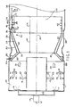
- 10 and 11 are sections of an annular premixing chamber or individual chambers in which fuel gas and air are premixed.
- the fuel gas 12 which may, for example, be natural gas or other hydrocarbon vapor, is provided through fuel flow controller 14 to one or more fuel nozzles such as 16 and 17 in premixing chambers 10 and 11, respectively.
- fuel flow controller 14 to one or more fuel nozzles such as 16 and 17 in premixing chambers 10 and 11, respectively.
- a single axisymmetric fuel nozzle such as 16 and 17 may be used for each premix chamber.
- Air is introduced through one or more entry ports such as 18. The air is provided to ports 18 from the gas turbine compressor (not shown) under an elevated pressure of five to fifteen atmospheres.
- the premixed fuel and air is provided to the interior of the combustion chamber 22 through venturi 24 formed by angular walls 32 meeting at the constriction or constricted throat 30.
- the combustion chamber 22 is generally cylindrical in shape about combustor centerline 26 and enclosed by outer walls 28 and 29.
- venturi 24 causes the fuel-air mixture moving downstream in the direction of arrows 31 and 33 to accelerate as it flows through the constricted throat 30 to the combustion chamber 22.
- venturi wall, 32 is adjacent the combustion chamber 22, it is necessary to cool the wall with back side impingement air flowing along and through passageway or channel 36 bounded by the venturi walls 32 and generally parallel walls 33.
- the cooling air 23 may be provided from the turbine compressor (not shown) through the wall 33, at inlet 25, or alternatively through louvers in the wall as described in the aforesaid United States Patent Number 4,292,801.
- the cooling medium may also be, or include, steam or water mixed with the air.
- the bulk flow detachment is caused by the rapid increase in geometric area downstream of the venturi throat 30.
- the path of the venturi cooling dump flow in a combustor in which the downstream exit 36 is directly connected to the interior of the combustion chamber 22 was found to be the reverse flow shown by dotted flow lines and arrows 42. Subsequent actual "fired" testing of that dry low NO x system has shown that reducing the amount of venturi cooling air entering the separated zone improved the stability of the premixed fuel burning operation.
- the exit channel 36 is connected through the passageway 44 extending downstream from the exit channel and formed by a cylindrical wall 46 which is concentric with and within combustor wall 28 to form the passageway therebetween.
- the wall 46 since it is also adjacent to the combustion chamber 22, is provided with some cooling such as back side impingement air, film air, or fins such as 48, to transfer heat away from the wall.
- the wall 46 may be the combustor shroud wall which is adjacent to the combustion process.
- the length 49 of the passageway 44 is optimized for each combustor design although it is in general some 8 to 10 times the radial width of the venturi exit channel 36.
- One embodiment of the invention was on a combustor 20 having an internal diameter of 10 inches, a distance 47 of 3 inches axially from the constricted throat 30 of venturi 24 to the downstream exit 49 of the exit channel 36 of the venturi, a throat diameter 30 of 7 inches, and a 2 inch axial length 49 of the passageway 44 formed by cylindrical wall 46 and wall 28.
- the internal diameter of the combustor 20 was varied from 10-14 inches
- the distance 47 was varied from 3-5 inches
- the diameter of the throat 30 was varied from 7-9 inches
- the length of the passageway 44 was varied from 2-7 inches.
- the present combustor provides a passageway of significant and sufficient length to carry the venturi cooling gas flow further downstream. It is believed that the cooling gas dump should be at least beyond the mid region of the separated zone 54.
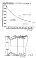
- FIG. 2 shows the effects of varying the length 49 of the passageway 44.
- the combustor exhaust temperatures in 0F are plotted on the Y axis and the ratio of the passageway 44 length/width are plotted on the X axis.
- the stable flame region is above the resultant plot or curve 57 while the cycling or unstable flame region is below the plot. It is to be noted that increasing the length/width ratio lowers the range of temperatures at which the combustor 20 provides a stable flame.
- FIG. 2 shows how the combustor exhaust temperature varies with changing the length of the venturi air dump 46, made dimensionless using the venturi diameter 30. Below the curve, the combustor begins to operate in a cyclic mode where the premixed combustion is unstable.
- the premixed fuel gas and air blows out As an example, if the dimensionless venturi air dump length is 0.25, the dry low No x combustor 20 can be operated stably at an exhaust temperature above 1900 degrees. Further, if the full load operating temperature is 2100 degrees, then the combustor can be operated in the premixed firing mode at partial load conditions corresponding to the range in exhaust temperature from 1900 to 2100 degrees. It is to be noted that the stable flame temperature may be lowered from in excess of 21000 F to less than 17000 F. This ability to maintain stable combustion over a wide range, including lower temperatures, has-achieved a desired reduction in the NO x and carbon monoxide (CO) emissions.
- CO carbon monoxide
- the benefits of the present combustor due to the improvement in the premixed operating mode of the dry low NO x combustor 20 are: (1) greater flexibility in operating the gas turbine because of a larger temperature range, including lower temperatures, over which the combustor is stable and can be fired in the premixed mode, (2) lowered resultant NO x emissions, (3) lowered CO emissions, (4) increased combustor lifetime and time between inspections due to lower system dynamic pressures, and (5) provision of a means of adjusting the combustor operation such that the emissions can be optimized for a given combustor nominal operating temperature.
- FIG. 3 shows an alternate embodiment of the present invention.
- the length of the passageway 44 is made adjustable to enable adjustable optimization of the present invention under variable operating conditions.
- a cylindrical sleeve 60 is slidably mounted closely within the passage to enable adjustment of the effective length of passageway 44. Because of the high temperatures and harsh environment of the interior of combustor 20 most installations may include a non-adjustable wall 46 which is designed for optimum operating characteristics.
- the adjustment mechanism shown schematically as controls 62 may be of any suitable type for the combustor 20 environment such as a rack and pinion mechanism or simply movement of the sleeve 60 by the control 62 moving within an axial slot 64 in wall 28, with control 62 being threaded fasteners to secure the sleeve in the desired location by screwing the fasteners tightly into the threaded bores 66 in the sleeve.
Landscapes
- Engineering & Computer Science (AREA)
- Chemical & Material Sciences (AREA)
- Combustion & Propulsion (AREA)
- Mechanical Engineering (AREA)
- General Engineering & Computer Science (AREA)
- Output Control And Ontrol Of Special Type Engine (AREA)
- Combustion Methods Of Internal-Combustion Engines (AREA)
Applications Claiming Priority (2)
| Application Number | Priority Date | Filing Date | Title |
|---|---|---|---|
| US474394 | 1990-02-05 | ||
| US07/474,394 US5117636A (en) | 1990-02-05 | 1990-02-05 | Low nox emission in gas turbine system |
Publications (2)
| Publication Number | Publication Date |
|---|---|
| EP0441542A1 true EP0441542A1 (de) | 1991-08-14 |
| EP0441542B1 EP0441542B1 (de) | 1994-04-27 |
Family
ID=23883334
Family Applications (1)
| Application Number | Title | Priority Date | Filing Date |
|---|---|---|---|
| EP91300808A Expired - Lifetime EP0441542B1 (de) | 1990-02-05 | 1991-02-01 | Brennkammer und Verbrennungsverfahren |
Country Status (7)
| Country | Link |
|---|---|
| US (1) | US5117636A (de) |
| EP (1) | EP0441542B1 (de) |
| JP (1) | JPH0769057B2 (de) |
| KR (1) | KR950013648B1 (de) |
| CN (1) | CN1050890C (de) |
| DE (1) | DE69101794T2 (de) |
| NO (1) | NO176116C (de) |
Cited By (5)
| Publication number | Priority date | Publication date | Assignee | Title |
|---|---|---|---|---|
| EP0672868A1 (de) * | 1994-03-14 | 1995-09-20 | General Electric Company | Verbrennungsvorrichtung für einer Gasturbinebrennkammer |
| US5592819A (en) * | 1994-03-10 | 1997-01-14 | Societe Nationale D'etude Et De Construction De Moteurs D'aviation S.N.E.C.M.A. | Pre-mixing injection system for a turbojet engine |
| EP1359008A1 (de) | 2002-04-29 | 2003-11-05 | Agfa-Gevaert | Strahlungsempfindliches Gemisch und damit hergestelltes Aufzeichnungsmaterial |
| EP1522792A1 (de) * | 2003-10-09 | 2005-04-13 | United Technologies Corporation | Brennkammer |
| US7314699B2 (en) | 2002-04-29 | 2008-01-01 | Agfa Graphics Nv | Radiation-sensitive mixture and recording material produced therewith |
Families Citing this family (46)
| Publication number | Priority date | Publication date | Assignee | Title |
|---|---|---|---|---|
| US5274991A (en) * | 1992-03-30 | 1994-01-04 | General Electric Company | Dry low NOx multi-nozzle combustion liner cap assembly |
| US5309710A (en) * | 1992-11-20 | 1994-05-10 | General Electric Company | Gas turbine combustor having poppet valves for air distribution control |
| US5669218A (en) * | 1995-05-31 | 1997-09-23 | Dresser-Rand Company | Premix fuel nozzle |
| GB9929601D0 (en) * | 1999-12-16 | 2000-02-09 | Rolls Royce Plc | A combustion chamber |
| WO2003093664A1 (en) * | 2000-06-28 | 2003-11-13 | Power Systems Mfg. Llc | Combustion chamber/venturi cooling for a low nox emission combustor |
| US6427446B1 (en) * | 2000-09-19 | 2002-08-06 | Power Systems Mfg., Llc | Low NOx emission combustion liner with circumferentially angled film cooling holes |
| US6430932B1 (en) | 2001-07-19 | 2002-08-13 | Power Systems Mfg., Llc | Low NOx combustion liner with cooling air plenum recesses |
| US6928822B2 (en) * | 2002-05-28 | 2005-08-16 | Lytesyde, Llc | Turbine engine apparatus and method |
| US6772595B2 (en) | 2002-06-25 | 2004-08-10 | Power Systems Mfg., Llc | Advanced cooling configuration for a low emissions combustor venturi |
| US6832482B2 (en) | 2002-06-25 | 2004-12-21 | Power Systems Mfg, Llc | Pressure ram device on a gas turbine combustor |
| CN100354565C (zh) * | 2002-10-10 | 2007-12-12 | Lpp燃烧有限责任公司 | 汽化燃烧用液体燃料的系统及其使用方法 |
| US6865892B2 (en) * | 2002-12-17 | 2005-03-15 | Power Systems Mfg, Llc | Combustion chamber/venturi configuration and assembly method |
| US7284378B2 (en) | 2004-06-04 | 2007-10-23 | General Electric Company | Methods and apparatus for low emission gas turbine energy generation |
| JP2006105534A (ja) * | 2004-10-07 | 2006-04-20 | Niigata Power Systems Co Ltd | ガスタービン燃焼器 |
| US7308793B2 (en) * | 2005-01-07 | 2007-12-18 | Power Systems Mfg., Llc | Apparatus and method for reducing carbon monoxide emissions |
| US7389643B2 (en) * | 2005-01-31 | 2008-06-24 | General Electric Company | Inboard radial dump venturi for combustion chamber of a gas turbine |
| JP2007147125A (ja) * | 2005-11-25 | 2007-06-14 | Mitsubishi Heavy Ind Ltd | ガスタービン燃焼器 |
| US7716931B2 (en) * | 2006-03-01 | 2010-05-18 | General Electric Company | Method and apparatus for assembling gas turbine engine |
| US8156743B2 (en) * | 2006-05-04 | 2012-04-17 | General Electric Company | Method and arrangement for expanding a primary and secondary flame in a combustor |
| US7878798B2 (en) * | 2006-06-14 | 2011-02-01 | John Zink Company, Llc | Coanda gas burner apparatus and methods |
| US7895841B2 (en) * | 2006-07-14 | 2011-03-01 | General Electric Company | Method and apparatus to facilitate reducing NOx emissions in turbine engines |
| US8707704B2 (en) * | 2007-05-31 | 2014-04-29 | General Electric Company | Method and apparatus for assembling turbine engines |
| US20090019854A1 (en) * | 2007-07-16 | 2009-01-22 | General Electric Company | APPARATUS/METHOD FOR COOLING COMBUSTION CHAMBER/VENTURI IN A LOW NOx COMBUSTOR |
| US8096133B2 (en) * | 2008-05-13 | 2012-01-17 | General Electric Company | Method and apparatus for cooling and dilution tuning a gas turbine combustor liner and transition piece interface |
| US7874157B2 (en) * | 2008-06-05 | 2011-01-25 | General Electric Company | Coanda pilot nozzle for low emission combustors |
| US8887390B2 (en) | 2008-08-15 | 2014-11-18 | Dresser-Rand Company | Method for correcting downstream deflection in gas turbine nozzles |
| FR2941287B1 (fr) * | 2009-01-19 | 2011-03-25 | Snecma | Paroi de chambre de combustion de turbomachine a une seule rangee annulaire d'orifices d'entree d'air primaire et de dilution |
| US7712314B1 (en) * | 2009-01-21 | 2010-05-11 | Gas Turbine Efficiency Sweden Ab | Venturi cooling system |
| US20100192587A1 (en) * | 2009-02-03 | 2010-08-05 | William Kirk Hessler | Combustor assembly for use in a gas turbine engine and method of assembling same |
| US20100319353A1 (en) * | 2009-06-18 | 2010-12-23 | John Charles Intile | Multiple Fuel Circuits for Syngas/NG DLN in a Premixed Nozzle |
| US20110167828A1 (en) * | 2010-01-08 | 2011-07-14 | Arjun Singh | Combustor assembly for a turbine engine that mixes combustion products with purge air |
| US8646277B2 (en) * | 2010-02-19 | 2014-02-11 | General Electric Company | Combustor liner for a turbine engine with venturi and air deflector |
| US20110225974A1 (en) * | 2010-03-22 | 2011-09-22 | General Electric Company | Multiple Zone Pilot For Low Emission Combustion System |
| US8931280B2 (en) | 2011-04-26 | 2015-01-13 | General Electric Company | Fully impingement cooled venturi with inbuilt resonator for reduced dynamics and better heat transfer capabilities |
| US8955329B2 (en) | 2011-10-21 | 2015-02-17 | General Electric Company | Diffusion nozzles for low-oxygen fuel nozzle assembly and method |
| GB201202907D0 (en) * | 2012-02-21 | 2012-04-04 | Doosan Power Systems Ltd | Burner |
| JP6326205B2 (ja) * | 2013-07-30 | 2018-05-16 | 三菱日立パワーシステムズ株式会社 | 燃料ノズル、燃焼器、及びガスタービン |
| US9752458B2 (en) | 2013-12-04 | 2017-09-05 | General Electric Company | System and method for a gas turbine engine |
| CN105805943A (zh) * | 2016-04-22 | 2016-07-27 | 广东三水大鸿制釉有限公司 | 一种热风烤窑装置及其使用方法 |
| CN108506935B (zh) * | 2018-05-28 | 2024-08-30 | 杭州浙大天元科技有限公司 | 基于燃气内循环的低NOx燃气燃烧器及降低排放的方法 |
| CN116265810B (zh) * | 2021-12-16 | 2025-09-26 | 通用电气公司 | 利用成形冷却栅栏的旋流器反稀释 |
| CN114486273B (zh) * | 2021-12-27 | 2024-08-30 | 国网浙江省电力有限公司电力科学研究院 | 一种园区灵活性改造机组氢混燃烧试验装置 |
| US11835236B1 (en) | 2022-07-05 | 2023-12-05 | General Electric Company | Combustor with reverse dilution air introduction |
| CN115523510B (zh) * | 2022-09-02 | 2023-10-13 | 哈尔滨工程大学 | 一种预混程度可调的氢燃料低排放燃烧室头部 |
| CN115638420A (zh) * | 2022-12-06 | 2023-01-24 | 无锡国联环保科技股份有限公司 | 一种用于流化床污泥焚烧炉的助燃装置和方法 |
| US12553608B1 (en) * | 2025-01-08 | 2026-02-17 | Pratt & Whitney Canada Corp. | Additively manufactured combustor liner v-band cooling ring |
Citations (5)
| Publication number | Priority date | Publication date | Assignee | Title |
|---|---|---|---|---|
| US3905192A (en) * | 1974-08-29 | 1975-09-16 | United Aircraft Corp | Combustor having staged premixing tubes |
| US3958416A (en) * | 1974-12-12 | 1976-05-25 | General Motors Corporation | Combustion apparatus |
| FR2336554A1 (fr) * | 1975-12-22 | 1977-07-22 | Gen Electric | Systeme de combustion pour turbines a gaz |
| US4413477A (en) * | 1980-12-29 | 1983-11-08 | General Electric Company | Liner assembly for gas turbine combustor |
| EP0273126A1 (de) * | 1986-11-25 | 1988-07-06 | General Electric Company | Gasturbinenbrennkammer |
Family Cites Families (11)
| Publication number | Priority date | Publication date | Assignee | Title |
|---|---|---|---|---|
| CH367662A (fr) * | 1959-07-07 | 1963-02-28 | Rover Co Ltd | Groupe à turbine à gaz |
| US3851466A (en) * | 1973-04-12 | 1974-12-03 | Gen Motors Corp | Combustion apparatus |
| US3958413A (en) * | 1974-09-03 | 1976-05-25 | General Motors Corporation | Combustion method and apparatus |
| US3946553A (en) * | 1975-03-10 | 1976-03-30 | United Technologies Corporation | Two-stage premixed combustor |
| US4420929A (en) * | 1979-01-12 | 1983-12-20 | General Electric Company | Dual stage-dual mode low emission gas turbine combustion system |
| US4292801A (en) * | 1979-07-11 | 1981-10-06 | General Electric Company | Dual stage-dual mode low nox combustor |
| DE2937631A1 (de) * | 1979-09-18 | 1981-04-02 | Daimler-Benz Ag, 7000 Stuttgart | Brennkammer fuer gasturbinen |
| US4845940A (en) * | 1981-02-27 | 1989-07-11 | Westinghouse Electric Corp. | Low NOx rich-lean combustor especially useful in gas turbines |
| GB2116308B (en) * | 1982-03-08 | 1985-11-13 | Westinghouse Electric Corp | Improved low-nox, rich-lean combustor |
| US4819438A (en) * | 1982-12-23 | 1989-04-11 | United States Of America | Steam cooled rich-burn combustor liner |
| US4912931A (en) * | 1987-10-16 | 1990-04-03 | Prutech Ii | Staged low NOx gas turbine combustor |
-
1990
- 1990-02-05 US US07/474,394 patent/US5117636A/en not_active Expired - Lifetime
-
1991
- 1991-01-23 JP JP3021344A patent/JPH0769057B2/ja not_active Expired - Lifetime
- 1991-02-01 EP EP91300808A patent/EP0441542B1/de not_active Expired - Lifetime
- 1991-02-01 DE DE69101794T patent/DE69101794T2/de not_active Expired - Lifetime
- 1991-02-04 KR KR1019910001856A patent/KR950013648B1/ko not_active Expired - Lifetime
- 1991-02-04 NO NO910418A patent/NO176116C/no not_active IP Right Cessation
- 1991-02-05 CN CN91100704A patent/CN1050890C/zh not_active Expired - Lifetime
Patent Citations (5)
| Publication number | Priority date | Publication date | Assignee | Title |
|---|---|---|---|---|
| US3905192A (en) * | 1974-08-29 | 1975-09-16 | United Aircraft Corp | Combustor having staged premixing tubes |
| US3958416A (en) * | 1974-12-12 | 1976-05-25 | General Motors Corporation | Combustion apparatus |
| FR2336554A1 (fr) * | 1975-12-22 | 1977-07-22 | Gen Electric | Systeme de combustion pour turbines a gaz |
| US4413477A (en) * | 1980-12-29 | 1983-11-08 | General Electric Company | Liner assembly for gas turbine combustor |
| EP0273126A1 (de) * | 1986-11-25 | 1988-07-06 | General Electric Company | Gasturbinenbrennkammer |
Cited By (6)
| Publication number | Priority date | Publication date | Assignee | Title |
|---|---|---|---|---|
| US5592819A (en) * | 1994-03-10 | 1997-01-14 | Societe Nationale D'etude Et De Construction De Moteurs D'aviation S.N.E.C.M.A. | Pre-mixing injection system for a turbojet engine |
| EP0672868A1 (de) * | 1994-03-14 | 1995-09-20 | General Electric Company | Verbrennungsvorrichtung für einer Gasturbinebrennkammer |
| US5575154A (en) * | 1994-03-14 | 1996-11-19 | General Electric Company | Dilution flow sleeve for reducing emissions in a gas turbine combustor |
| EP1359008A1 (de) | 2002-04-29 | 2003-11-05 | Agfa-Gevaert | Strahlungsempfindliches Gemisch und damit hergestelltes Aufzeichnungsmaterial |
| US7314699B2 (en) | 2002-04-29 | 2008-01-01 | Agfa Graphics Nv | Radiation-sensitive mixture and recording material produced therewith |
| EP1522792A1 (de) * | 2003-10-09 | 2005-04-13 | United Technologies Corporation | Brennkammer |
Also Published As
| Publication number | Publication date |
|---|---|
| CN1054823A (zh) | 1991-09-25 |
| JPH04214122A (ja) | 1992-08-05 |
| EP0441542B1 (de) | 1994-04-27 |
| CN1050890C (zh) | 2000-03-29 |
| NO176116B (no) | 1994-10-24 |
| JPH0769057B2 (ja) | 1995-07-26 |
| DE69101794D1 (de) | 1994-06-01 |
| NO910418D0 (no) | 1991-02-04 |
| KR950013648B1 (ko) | 1995-11-13 |
| NO910418L (no) | 1991-08-06 |
| US5117636A (en) | 1992-06-02 |
| KR910015817A (ko) | 1991-09-30 |
| DE69101794T2 (de) | 1994-12-15 |
| NO176116C (no) | 1995-02-01 |
Similar Documents
| Publication | Publication Date | Title |
|---|---|---|
| EP0441542B1 (de) | Brennkammer und Verbrennungsverfahren | |
| US5285631A (en) | Low NOx emission in gas turbine system | |
| US4420929A (en) | Dual stage-dual mode low emission gas turbine combustion system | |
| US6826913B2 (en) | Airflow modulation technique for low emissions combustors | |
| US4356698A (en) | Staged combustor having aerodynamically separated combustion zones | |
| US4928481A (en) | Staged low NOx premix gas turbine combustor | |
| US5974781A (en) | Hybrid can-annular combustor for axial staging in low NOx combustors | |
| US5127221A (en) | Transpiration cooled throat section for low nox combustor and related process | |
| US6951108B2 (en) | Gas turbine engine combustor can with trapped vortex cavity | |
| US8033112B2 (en) | Swirler with gas injectors | |
| EP2107301B1 (de) | Gaseinspritzung in einem Brenner | |
| US5494437A (en) | Gas burner | |
| EP0479414A1 (de) | Brenner mit geringer NOX-Produktion | |
| US20090019854A1 (en) | APPARATUS/METHOD FOR COOLING COMBUSTION CHAMBER/VENTURI IN A LOW NOx COMBUSTOR | |
| GB2449267A (en) | Cool diffusion flame combustion | |
| GB2040031A (en) | Dual stage-dual mode low emission gas turbine combustion system | |
| US4351156A (en) | Combustion systems | |
| US9464809B2 (en) | Gas turbine combustor and operating method for gas turbine combustor | |
| US5551869A (en) | Gas staged burner | |
| EP1407197B1 (de) | Drehströmungsfeuerung | |
| CN101539305B (zh) | 燃气轮机引擎的稳定燃烧用导引燃烧器室 | |
| US4339924A (en) | Combustion systems | |
| WO1998040670A1 (en) | AN IMPROVED COMBUSTOR FOR LOW CO, LOW NOx FORMATION | |
| Kishi et al. | Characteristics of hydrogen combustion in an experimental lean premixed combustor | |
| GB2044433A (en) | Improved gas turbine engines operating on gaseous fuels |
Legal Events
| Date | Code | Title | Description |
|---|---|---|---|
| PUAI | Public reference made under article 153(3) epc to a published international application that has entered the european phase |
Free format text: ORIGINAL CODE: 0009012 |
|
| AK | Designated contracting states |
Kind code of ref document: A1 Designated state(s): CH DE FR GB IT LI NL SE |
|
| 17P | Request for examination filed |
Effective date: 19911220 |
|
| 17Q | First examination report despatched |
Effective date: 19921120 |
|
| GRAA | (expected) grant |
Free format text: ORIGINAL CODE: 0009210 |
|
| AK | Designated contracting states |
Kind code of ref document: B1 Designated state(s): CH DE FR GB IT LI NL SE |
|
| REF | Corresponds to: |
Ref document number: 69101794 Country of ref document: DE Date of ref document: 19940601 |
|
| ET | Fr: translation filed | ||
| ITF | It: translation for a ep patent filed | ||
| EAL | Se: european patent in force in sweden |
Ref document number: 91300808.2 |
|
| PLBE | No opposition filed within time limit |
Free format text: ORIGINAL CODE: 0009261 |
|
| STAA | Information on the status of an ep patent application or granted ep patent |
Free format text: STATUS: NO OPPOSITION FILED WITHIN TIME LIMIT |
|
| 26N | No opposition filed | ||
| REG | Reference to a national code |
Ref country code: GB Ref legal event code: IF02 |
|
| PGFP | Annual fee paid to national office [announced via postgrant information from national office to epo] |
Ref country code: CH Payment date: 20100224 Year of fee payment: 20 |
|
| PGFP | Annual fee paid to national office [announced via postgrant information from national office to epo] |
Ref country code: IT Payment date: 20100224 Year of fee payment: 20 Ref country code: FR Payment date: 20100303 Year of fee payment: 20 |
|
| PGFP | Annual fee paid to national office [announced via postgrant information from national office to epo] |
Ref country code: DE Payment date: 20100226 Year of fee payment: 20 Ref country code: GB Payment date: 20100224 Year of fee payment: 20 |
|
| PGFP | Annual fee paid to national office [announced via postgrant information from national office to epo] |
Ref country code: NL Payment date: 20100223 Year of fee payment: 20 |
|
| PGFP | Annual fee paid to national office [announced via postgrant information from national office to epo] |
Ref country code: SE Payment date: 20100226 Year of fee payment: 20 |
|
| REG | Reference to a national code |
Ref country code: DE Ref legal event code: R071 Ref document number: 69101794 Country of ref document: DE |
|
| REG | Reference to a national code |
Ref country code: NL Ref legal event code: V4 Effective date: 20110201 |
|
| REG | Reference to a national code |
Ref country code: CH Ref legal event code: PL |
|
| REG | Reference to a national code |
Ref country code: GB Ref legal event code: PE20 Expiry date: 20110131 |
|
| EUG | Se: european patent has lapsed | ||
| PG25 | Lapsed in a contracting state [announced via postgrant information from national office to epo] |
Ref country code: NL Free format text: LAPSE BECAUSE OF EXPIRATION OF PROTECTION Effective date: 20110201 |
|
| PG25 | Lapsed in a contracting state [announced via postgrant information from national office to epo] |
Ref country code: GB Free format text: LAPSE BECAUSE OF EXPIRATION OF PROTECTION Effective date: 20110131 |
|
| PG25 | Lapsed in a contracting state [announced via postgrant information from national office to epo] |
Ref country code: DE Free format text: LAPSE BECAUSE OF EXPIRATION OF PROTECTION Effective date: 20110201 |