EP0441616A2 - Anisotropic plastic bonded magnet of the Nd-Fe-B-type and method for making same - Google Patents
Anisotropic plastic bonded magnet of the Nd-Fe-B-type and method for making same Download PDFInfo
- Publication number
- EP0441616A2 EP0441616A2 EP91300981A EP91300981A EP0441616A2 EP 0441616 A2 EP0441616 A2 EP 0441616A2 EP 91300981 A EP91300981 A EP 91300981A EP 91300981 A EP91300981 A EP 91300981A EP 0441616 A2 EP0441616 A2 EP 0441616A2
- Authority
- EP
- European Patent Office
- Prior art keywords
- magnetic powder
- magnetic
- weight
- bonded magnet
- plastic bonded
- Prior art date
- Legal status (The legal status is an assumption and is not a legal conclusion. Google has not performed a legal analysis and makes no representation as to the accuracy of the status listed.)
- Granted
Links
Images


Classifications
-
- H—ELECTRICITY
- H01—ELECTRIC ELEMENTS
- H01F—MAGNETS; INDUCTANCES; TRANSFORMERS; SELECTION OF MATERIALS FOR THEIR MAGNETIC PROPERTIES
- H01F1/00—Magnets or magnetic bodies characterised by the magnetic materials therefor; Selection of materials for their magnetic properties
- H01F1/01—Magnets or magnetic bodies characterised by the magnetic materials therefor; Selection of materials for their magnetic properties of inorganic materials
- H01F1/03—Magnets or magnetic bodies characterised by the magnetic materials therefor; Selection of materials for their magnetic properties of inorganic materials characterised by their coercivity
- H01F1/032—Magnets or magnetic bodies characterised by the magnetic materials therefor; Selection of materials for their magnetic properties of inorganic materials characterised by their coercivity of hard-magnetic materials
- H01F1/04—Magnets or magnetic bodies characterised by the magnetic materials therefor; Selection of materials for their magnetic properties of inorganic materials characterised by their coercivity of hard-magnetic materials metals or alloys
- H01F1/047—Alloys characterised by their composition
- H01F1/053—Alloys characterised by their composition containing rare earth metals
- H01F1/055—Alloys characterised by their composition containing rare earth metals and magnetic transition metals, e.g. SmCo5
- H01F1/057—Alloys characterised by their composition containing rare earth metals and magnetic transition metals, e.g. SmCo5 and IIIa elements, e.g. Nd2Fe14B
- H01F1/0571—Alloys characterised by their composition containing rare earth metals and magnetic transition metals, e.g. SmCo5 and IIIa elements, e.g. Nd2Fe14B in the form of particles, e.g. rapid quenched powders or ribbon flakes
- H01F1/0575—Alloys characterised by their composition containing rare earth metals and magnetic transition metals, e.g. SmCo5 and IIIa elements, e.g. Nd2Fe14B in the form of particles, e.g. rapid quenched powders or ribbon flakes pressed, sintered or bonded together
- H01F1/0578—Alloys characterised by their composition containing rare earth metals and magnetic transition metals, e.g. SmCo5 and IIIa elements, e.g. Nd2Fe14B in the form of particles, e.g. rapid quenched powders or ribbon flakes pressed, sintered or bonded together bonded together
Definitions
- This invention relates to a plastic bonded magnet containing an anisotropic neodymium-iron-boron system magnetic powder.
- magnets are used in various devices including stepping motors, spindle motors, torque motors, automotive motors, various actuators, speakers, and other magnetic-field generating devices.
- the invention provides a plastic bonded magnet which comprises an anisotropic neodymium-iron-boron system magnetic powder and a resin binder characterised in that from 10 to 20% weight of the magnetic powder has a grain size in the range 10 to 49 microns ( ⁇ m).
- the magnetic powder grain distribution used in the magnets of the invention can be obtained by kneading and dispersing the powder (together with a binder) in a high-speed shearing machine.
- a higher (BH) max is obtained due to a substantially improved magnetic orientation in the compressed molded body of the plastic bonded magnet. Furthermore, an extended pot-life of molding compound and higher (BH) max value can be obtained by employing an epoxy resin as the binder and curing it with a latent hardening agent which is an amine adduct of the epoxy resin.
- FIG. 1 there is shown a magnet of the invention wherein 1 is anisotropic neodymium-iron-boron system magnetic powder having a grain size distribution from 50 to 500 microns, reference 2 is anisotropic neodymium-iron-boron system magnetic powder having grain sizes from 10 to 49 microns, and 3 is the plastic resin binder.
- the anisotropic neodymium-iron-boron system magnetic powder employed in this invention can be anisotropic neodymium-iron-boron system magnetic powder manufactured by upsetting its overquenched melt-spun ribbon.
- the magnets may also comprise, in addition, elements such as zirconium, gallium, cobalt, praseodymium, and tin for improving temperature characteristics, anti-corrosion properties, and magnetic properties as will be understood by those skilled in the art.
- the magnetic powder employed in the invention has excellent magnetic properties, (magnetization 4 ⁇ I, coercive force iH c ) which are substantially governed by the grain size distribution as shown in Figure 2.
- the magnetic characteristics of the fine powder having grain sizes of 10 to 49 microns ( ⁇ m) are significantly different from those of powder of greater grain size, as Fig. 2 illustrates.
- the invention does not use exclusively powder having grain sizes less than 49 microns: such magnets would have inferior magnetic properties. Rather, the invention introduces a limited amount only of such powder into the molding composition to improve the magnetic orientation.
- the magnetic orientation of the plastic bonded magnet is highly improved by introducing magnetic powder having fine grain sizes from 10 to 49 microns ( ⁇ m) in an amount of 10 to 20% by weight. The reason for this cannot be attributed to higher magnetic powder density, but we believe it can be attributed to the improved flowability of the molding composition.
- Magnetic powder having grain sizes less than 10 microns ( ⁇ m) because of its poor magnetic characteristics.
- the content of fine magnetic powder (10 to 49 microns ( ⁇ m) should be limited to less than 20% by weight, but the orientation effect cannot be attained if its content is less than 10% by weight.
- large sized magnetic powder having grain sizes more than 500 microns ( ⁇ m) has excellent magnetic characteristics, it causes a reduction in mold density and as a result no improvement in residual magnetic flux density B r can be expected.
- the molding composition will contain a suitable dispersing agent.
- Fatty acids, silicone-coupling agents and various surface-active agents can be employed, we prefer to use a liquid fatty acid, eg. oleic acid. This ability to function as a dispersing agent is attributed to the higher affinity for the magnetic powder. This is not shown by any of the solid fatty acids.
- the use of liquid fatty acids is particularly advantageous in compressive molding which is performed conventionally at room temperature since it improves productivity.
- fatty acid additive Although it is important to keep the amount of fatty acid additive as low as possible, it is preferred to introduce at least 0.8% by weight thereof (based on the weight of the magnetic powder). An amount of fatty acid less than 0.7% by weight usually results in an inadequate affinity to the magnetic powder resulting in reduced density and (BH) max . On the other hand, if an excessive amount of fatty acid is used, eg. more than 1.3% by weight, oozing of binder tends to occur and lower strength of the molded magnet results.
- binders Whilst various binders can be used in the present invention, for room temperature molding we prefer to use liquid epoxy resin to give good adhesion strength.
- the total amount of binder is determined by the attainable magnetic characteristics and the strength of the molding.
- the total amount of binder component used depends on the magnetic characteristics required and the strength of the molded magnet. If an amount of binder of less than 1.4% by weight is mixed with the magnetic powder, this would usually result in inadequate mold strength, but if more than 3.0% by weight is used, this would result in poor magnetic characteristics.
- Any suitable curing or hardening agent can be used.
- Amines and acid anhydrides are generally preferred. If an amine adduct of epoxy resin is used as a hardening agent for epoxy resin used as a binder, a substantially extended pot-life of the molding composition can be obtained relative to the use of a conventional amine system hardening agent.
- the molding composition is preferably prepared in a high-speed shearing machine capable of pulverizing and mixing the magnetic powder, such as a Henschell mixer, upper-mill, high-speed mixer, or a micro-mill grinder.
- a high-speed shearing machine capable of pulverizing and mixing the magnetic powder, such as a Henschell mixer, upper-mill, high-speed mixer, or a micro-mill grinder.
- a plastic bonded magnetic material mixture consisting of 100 weight parts of anisotropic Nd-Fe-B system magnetic powder having grain sizes from 1 to 2 mm and 0.9 weight part of oleic acid as a dispersion agent, are ground in a micro-mill grinder for about five minutes, and 1.0 weight part of epoxy resin, eg. Epikote 828 (manufactured by Yuka-Shell Epoxy Co.), is added thereto, and ground for another ten minutes.
- epoxy resin eg. Epikote 828 (manufactured by Yuka-Shell Epoxy Co.
- the dispersion process is completed by adding 0.9 weight parts of acid anhydride, eg. Kayahard MCD (manufactured by Nihon Kayaku Co.), and 0.01 weight parts of catalytic imidazone, eg. Epikure EMI-24 (manufactured by Shikoku Kasei Kogyo Co.) thereto, and the mixing continued for another ten minutes.
- acid anhydride eg. Kayahard MCD (manufactured by Nihon Kayaku Co.)
- catalytic imidazone eg. Epikure EMI-24 (manufactured by Shikoku Kasei Kogyo Co.)
- the molding composition so made is loaded into a die cavity, and is molded at room temperature using a pressure of 6 ton/cm2 (6 x 10⁸ Pa) under application of a magnetic field of 15 KOe. After a hardening process conducted at 100°C for one hour, a plastic bonded magnet of the invention is produced.
- a molded article before hardening is removed from a mold and immersed in acetone to remove resin components.
- the magnetic powder obtained is dried in a nitrogen atmosphere. The grain size distribution of this magnetic powder was measured and found to be:
- Example 1 For comparison purpose, the procedure of Example 1 is repeated except that magnetic powder having grain sizes from 300 to 500 um is used as starting material.
- the grain size distribution in this case was measured and was found to be:
- Example 1 is repeated except that magnetic powder having grain sizes from 3 to 4 mm is used.
- the grain size distribution was found to be:
- Example 1 is repeated except that this time the mixture is ground for 12 hours in a ball-mill using acetone as a solvent and then the acetone is evacuated.
- the grain size distribution was found to be:
- Example 1 The general procedure of Example 1 is followed except that an electromagnetic steel plate made of soft magnetic material is inserted in the die before the molding composition is injected. The molding is then conducted at room temperature under a pressure of 6 ton/cm2 (6 x 10⁸ Pa) and a magnetic field of 15 KOe. After a hardening process at 100°C for two hours, a plastic bonded magnet having an integrated electromagnetic steel plate made of soft magnetic material, is obtained. The adhesion between the soft steel plate and plastic bonded magnet was found adequately high.
- the degree of magnetic orientation is defined as B r (//)/ (B r (//) + B r ( ⁇ )]. This represents the ease of movement of magnetic powder under application of an external magnetic field, and a higher value means a higher magnetic orientation.
- B r (//) and B r ( ⁇ ) represent a residual magnetic flux density along the applied magnetic field and a residual magnetic flux density perpendicular to the applied magnetic field, respectively.
- Table 1 shows that plastic bonded magnets having higher densities, degrees of magnetic orientation and (BH) max values can be obtained by the present invention.
- FIGs. 3,4 and 5 Changes in grain configurations of magnetic powder are shown in Figs. 3,4 and 5.
- Figure 3 shows a schematic configuration of raw magnetic powder material
- Figure 4 is a schematic showing the rounded-off grains of powder after pulverization and mixing conducted by a high-speed shearing machine which is employed to prepare the magnet of Example 1.
- Figure 5 is a schematic diagram showing grain configuration of magnetic powder after kneading and dispersion of the magnetic powder of Comparison 3, showing more squarish and smaller grain sizes compared with those shown in Figure 4.
- This improvement of magnetic orientation is attributed to the improved flowability of the compressive molding composition containing fine magnetic powder having grain sizes from 10 to 49 ⁇ m in amounts from 10 to 20% by weight. Hitherto, the use of this type of magnetic powder had been avoided because of its lower magnetic characteristics.
- Example 1 the improvement of (BH) max is attributed to the higher magnetic orientation and improved density due to using magnetic powder which is rounded-off during said high-speed shearing process.
- the density of the magnet of Comparison 2 is 6.15 which is low because it contains magnetic powder having grain sizes from 1 to 2mm, and thus, the (BH) max is low also.
- An anisotropic Nd-Fe-B system magnetic powder having an average grain size of 1mm and oleic acid are mixed at a weight ratio of 100 to 0.9, and this mixture is kneaded for 10 minutes in a high-speed mixer under a nitrogen atmosphere.
- an epoxy resin eg. Epikote-828 manufactured by Yuka-Shell Epoxy Co.
- a latent hardening agent eg. Amicure PN-23, manufactured by Ajinomoto Co.
- the resulting molding composition is then loaded into a cavity for applying a compressive pressure of 6 ton/cm2 with an applied magnetic field of 15 KOe.
- the anisotropic plastic bonded magnet is produced after hardening for one hour at 100°C.
- Example 3 is repeated except that the materials are as follows:
- Example 3 is repeated except that the materials used were:
- the initial magnetic characteristics, (BH) max , of the magnets, and the pot-life of the molding compositions are shown in Table 2.
- the pot-life was determined as follows. The molding composition is left still at room temperature, and samples are taken out every one hour and used to mold a sample plastic bonded magnet under the above-described conditions. The elapsed time at which a sample of the composition forms a magnet which shows a magnetic characteristic which is lower by 5 % than that of the initial magnet is defined as the pot-life of the composition.
- the plastic bonded magnet shown in Example 3 wherein a latent hardening agent is used showed a value of (BH) max as high as 15 MGOe and a pot-life as long as 20 hours, which are very useful features.
- the use of a high-speed shearing machine minimizes the possibility of stability damage of binder system due to the local heat produced at kneading.
- the magnet produced by using an aliphatic amine hardening agent, shown in Comparison 4 had a value of (BH) max of 12 MGOe and a pot life of only 3 hours, and this has little practical value.
- an aromatic amine hardening agent as shown in Comparison 5 gave a value of (BH) max of 15 MGOe which is reasonably high, the pot life of 6 hours is still considered inadequate for practical purposes.
- the (BH) max of the magnet, and the pot-life of the composition are influenced by the type of hardening agent.
- the difference between magnetic characteristics of the magnets can be attributed in part to the difference between the affinities of binders for the magnetic powder, which results in the difference between dispersibilities.
- the difference between pot-lives can be attributed to the difference between thermal stabilities of the binder systems against local heat generation.
- the latent hardening agent employed i.e. a hardening agent which does not start hardening until a certain time is elapsed after it is mixed with a primary epoxy agent, is much preferred. This hardening system has a high thermal stability, and is thus considered highly useful to extend the pot-life.
Landscapes
- Chemical & Material Sciences (AREA)
- Crystallography & Structural Chemistry (AREA)
- Inorganic Chemistry (AREA)
- Engineering & Computer Science (AREA)
- Power Engineering (AREA)
- Hard Magnetic Materials (AREA)
Abstract
Description
- This invention relates to a plastic bonded magnet containing an anisotropic neodymium-iron-boron system magnetic powder. Such magnets are used in various devices including stepping motors, spindle motors, torque motors, automotive motors, various actuators, speakers, and other magnetic-field generating devices.
- Extensive efforts have been made to improve the maximum energy product (hereinafter abbreviated to (BH)max of resin-bonded rare-earth magnets. There are three essential requirements for a higher (BH)max plastic bonded magnet, namely (1) higher magnetization 4 I and higher coercive force iHc, (2) higher mold density, and (3) higher magnetic orientation of the magnetic powder. While various ways have been found to attain requirements (1) and (2), including those methods disclosed by in Japanese Laid-Open Patents Sho 60-207302 and Sho 60-220907, virtually no satisfactory way has to date been found to improve the magnetic powder orientation.
- We have now devised a new neodymium-iron-boron system plastic bonded magnet having an improved (BH)max achieved by attaining a higher orientation of the magnetic powder thereof. In particular the invention provides a plastic bonded magnet which comprises an anisotropic neodymium-iron-boron system magnetic powder and a resin binder characterised in that from 10 to 20% weight of the magnetic powder has a grain size in the
range 10 to 49 microns (µm). - The magnetic powder grain distribution used in the magnets of the invention can be obtained by kneading and dispersing the powder (together with a binder) in a high-speed shearing machine.
- By using the above-described magnetic powder constitution, a higher (BH)max is obtained due to a substantially improved magnetic orientation in the compressed molded body of the plastic bonded magnet. Furthermore, an extended pot-life of molding compound and higher (BH)max value can be obtained by employing an epoxy resin as the binder and curing it with a latent hardening agent which is an amine adduct of the epoxy resin.
- In order that the invention may be more fully understood, reference will be made to the accompanying drawings, wherein:
- Figure 1 is an enlarged cross-section of one embodiment of plastic bonded magnet of the invention;
- Figure 2 shows the relationship between the grain-size of magnetic powder of the invention and the magnetic characteristics;
- Figure 3 is a schematic representation of magnetic powder employed in Example 1;
- Figure 4 is a schematic representation showing the magnetic powder grain configuration after kneading and dispersion of the magnetic powder shown in Figure 1; and
- Figure 5 is a schematic diagram of the magnetic powder grain configuration after kneading and dispersion of magnetic powder used in Example 3.
- Referring now to Figure 1, there is shown a magnet of the invention wherein 1 is anisotropic neodymium-iron-boron system magnetic powder having a grain size distribution from 50 to 500 microns,
reference 2 is anisotropic neodymium-iron-boron system magnetic powder having grain sizes from 10 to 49 microns, and 3 is the plastic resin binder. The anisotropic neodymium-iron-boron system magnetic powder employed in this invention can be anisotropic neodymium-iron-boron system magnetic powder manufactured by upsetting its overquenched melt-spun ribbon. - The magnets may also comprise, in addition, elements such as zirconium, gallium, cobalt, praseodymium, and tin for improving temperature characteristics, anti-corrosion properties, and magnetic properties as will be understood by those skilled in the art.
- The magnetic powder employed in the invention has excellent magnetic properties, (magnetization 4πI, coercive force iHc) which are substantially governed by the grain size distribution as shown in Figure 2. Thus, the magnetic characteristics of the fine powder having grain sizes of 10 to 49 microns (µm) are significantly different from those of powder of greater grain size, as Fig. 2 illustrates.
- It will be understood that the invention does not use exclusively powder having grain sizes less than 49 microns: such magnets would have inferior magnetic properties. Rather, the invention introduces a limited amount only of such powder into the molding composition to improve the magnetic orientation. The magnetic orientation of the plastic bonded magnet is highly improved by introducing magnetic powder having fine grain sizes from 10 to 49 microns (µm) in an amount of 10 to 20% by weight. The reason for this cannot be attributed to higher magnetic powder density, but we believe it can be attributed to the improved flowability of the molding composition.
- We prefer to exclude magnetic powder having grain sizes less than 10 microns (µm) because of its poor magnetic characteristics. The content of fine magnetic powder (10 to 49 microns (µm) should be limited to less than 20% by weight, but the orientation effect cannot be attained if its content is less than 10% by weight. Although large sized magnetic powder having grain sizes more than 500 microns (µm) has excellent magnetic characteristics, it causes a reduction in mold density and as a result no improvement in residual magnetic flux density Br can be expected.
- The molding composition will contain a suitable dispersing agent. Fatty acids, silicone-coupling agents and various surface-active agents can be employed, we prefer to use a liquid fatty acid, eg. oleic acid. This ability to function as a dispersing agent is attributed to the higher affinity for the magnetic powder. This is not shown by any of the solid fatty acids. The use of liquid fatty acids is particularly advantageous in compressive molding which is performed conventionally at room temperature since it improves productivity.
- Although it is important to keep the amount of fatty acid additive as low as possible, it is preferred to introduce at least 0.8% by weight thereof (based on the weight of the magnetic powder). An amount of fatty acid less than 0.7% by weight usually results in an inadequate affinity to the magnetic powder resulting in reduced density and (BH)max. On the other hand, if an excessive amount of fatty acid is used, eg. more than 1.3% by weight, oozing of binder tends to occur and lower strength of the molded magnet results.
- Whilst various binders can be used in the present invention, for room temperature molding we prefer to use liquid epoxy resin to give good adhesion strength. The total amount of binder is determined by the attainable magnetic characteristics and the strength of the molding. The total amount of binder component used depends on the magnetic characteristics required and the strength of the molded magnet. If an amount of binder of less than 1.4% by weight is mixed with the magnetic powder, this would usually result in inadequate mold strength, but if more than 3.0% by weight is used, this would result in poor magnetic characteristics.
- Any suitable curing or hardening agent can be used. Amines and acid anhydrides are generally preferred. If an amine adduct of epoxy resin is used as a hardening agent for epoxy resin used as a binder, a substantially extended pot-life of the molding composition can be obtained relative to the use of a conventional amine system hardening agent.
- The molding composition is preferably prepared in a high-speed shearing machine capable of pulverizing and mixing the magnetic powder, such as a Henschell mixer, upper-mill, high-speed mixer, or a micro-mill grinder.
- The following Examples illustrate the invention. The comparisons are not according to the invention.
- A plastic bonded magnetic material mixture consisting of 100 weight parts of anisotropic Nd-Fe-B system magnetic powder having grain sizes from 1 to 2 mm and 0.9 weight part of oleic acid as a dispersion agent, are ground in a micro-mill grinder for about five minutes, and 1.0 weight part of epoxy resin, eg. Epikote 828 (manufactured by Yuka-Shell Epoxy Co.), is added thereto, and ground for another ten minutes.
- The dispersion process is completed by adding 0.9 weight parts of acid anhydride, eg. Kayahard MCD (manufactured by Nihon Kayaku Co.), and 0.01 weight parts of catalytic imidazone, eg. Epikure EMI-24 (manufactured by Shikoku Kasei Kogyo Co.) thereto, and the mixing continued for another ten minutes.
- The molding composition so made is loaded into a die cavity, and is molded at room temperature using a pressure of 6 ton/cm² (6 x 10⁸ Pa) under application of a magnetic field of 15 KOe. After a hardening process conducted at 100°C for one hour, a plastic bonded magnet of the invention is produced.
- For purposes of analysis, a molded article before hardening is removed from a mold and immersed in acetone to remove resin components. The magnetic powder obtained is dried in a nitrogen atmosphere. The grain size distribution of this magnetic powder was measured and found to be:

- For comparison purpose, the procedure of Example 1 is repeated except that magnetic powder having grain sizes from 300 to 500 um is used as starting material. The grain size distribution in this case was measured and was found to be:

- Example 1 is repeated except that magnetic powder having grain sizes from 3 to 4 mm is used. The grain size distribution was found to be:
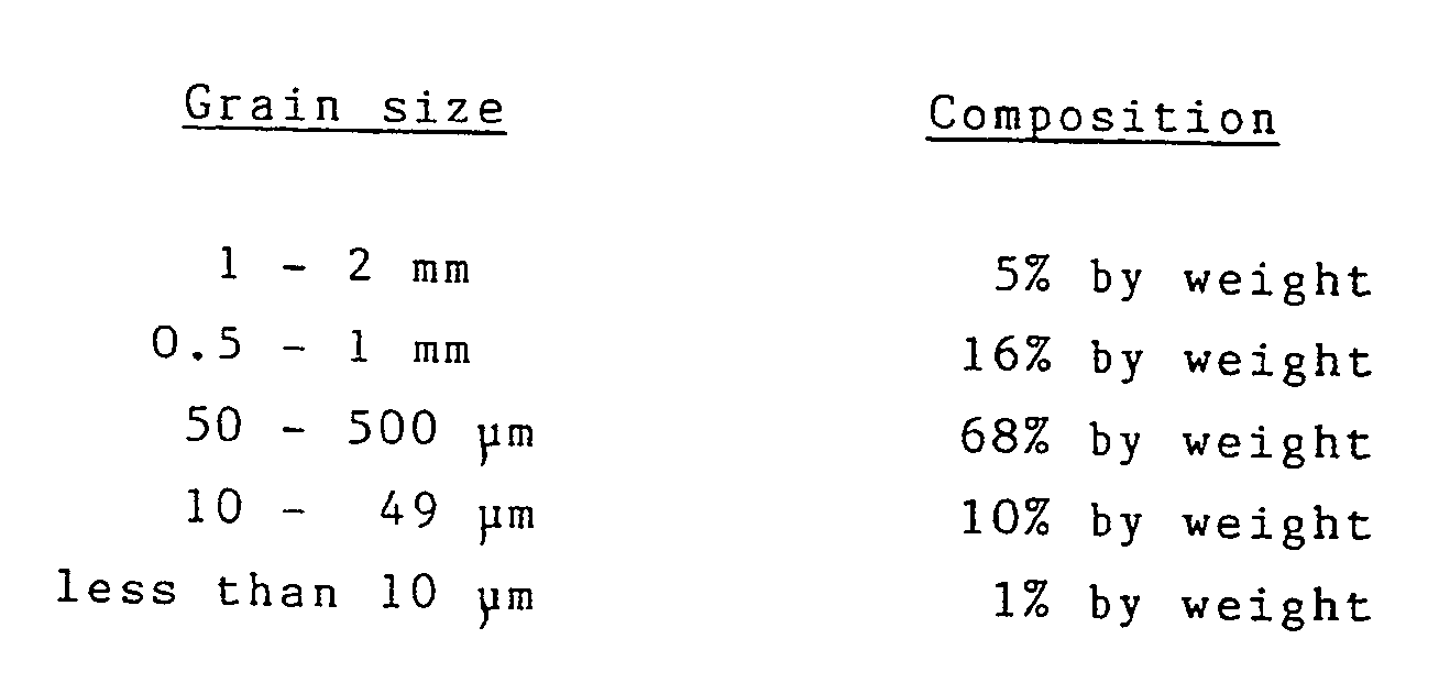
- Example 1 is repeated except that this time the mixture is ground for 12 hours in a ball-mill using acetone as a solvent and then the acetone is evacuated. The grain size distribution was found to be:
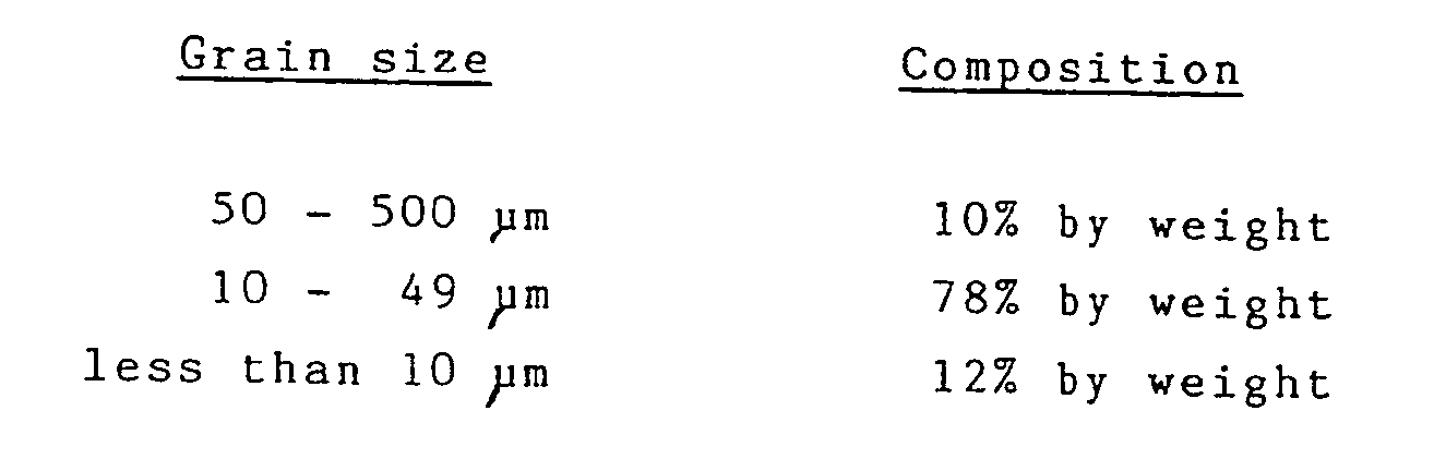
- The general procedure of Example 1 is followed except that an electromagnetic steel plate made of soft magnetic material is inserted in the die before the molding composition is injected. The molding is then conducted at room temperature under a pressure of 6 ton/cm² (6 x 10⁸ Pa) and a magnetic field of 15 KOe. After a hardening process at 100°C for two hours, a plastic bonded magnet having an integrated electromagnetic steel plate made of soft magnetic material, is obtained. The adhesion between the soft steel plate and plastic bonded magnet was found adequately high.
- The determined densities, magnetic characteristics and magnetic orientations of the plastic magnets obtained in Example 1 and in
Comparisons - The degree of magnetic orientation is defined as Br(//)/ (Br(//) + Br(┴)]. This represents the ease of movement of magnetic powder under application of an external magnetic field, and a higher value means a higher magnetic orientation. Br(//) and Br(┴) represent a residual magnetic flux density along the applied magnetic field and a residual magnetic flux density perpendicular to the applied magnetic field, respectively.

- Table 1 shows that plastic bonded magnets having higher densities, degrees of magnetic orientation and (BH)max values can be obtained by the present invention.
- Changes in grain configurations of magnetic powder are shown in Figs. 3,4 and 5. Figure 3 shows a schematic configuration of raw magnetic powder material, and Figure 4 is a schematic showing the rounded-off grains of powder after pulverization and mixing conducted by a high-speed shearing machine which is employed to prepare the magnet of Example 1. Figure 5 is a schematic diagram showing grain configuration of magnetic powder after kneading and dispersion of the magnetic powder of
Comparison 3, showing more squarish and smaller grain sizes compared with those shown in Figure 4. - Thus, as shown in Figure 1, higher magnetic orientation and higher density, and higher (BH)max, can be realized by the grain size changes in accordance with the invention, for example produced by the pulverization and dispersion process using a high-speed shearing machine, as described. Whilst we do not wish to be bound by theory, we believe that the reasons for these improvements can be explained as follows. Whereas the magnet of Example 1 contains 14% by weight magnetic powder having grain sizes from 10 to 49 um, the amounts in
Comparisons Comparison 2 are due to the containment of 10 to 20% by weight magnetic powder having grain sizes from 10 to 49 µm. While the magnetic orientation is 0.70 and 0.68 in Example 1 andComparison 2, respectively, it is only 0.65 inComparison 3. - This improvement of magnetic orientation is attributed to the improved flowability of the compressive molding composition containing fine magnetic powder having grain sizes from 10 to 49 µm in amounts from 10 to 20% by weight. Hitherto, the use of this type of magnetic powder had been avoided because of its lower magnetic characteristics.
- Furthermore, as shown in Example 1, the improvement of (BH)max is attributed to the higher magnetic orientation and improved density due to using magnetic powder which is rounded-off during said high-speed shearing process. The density of the magnet of
Comparison 2 is 6.15 which is low because it contains magnetic powder having grain sizes from 1 to 2mm, and thus, the (BH)max is low also. - This means that the improvements of both orientation and density contribute to the improved (BH)max, achieved by the present invention. Further, in the plastic bonded magnet containing an integrated soft magnetic plate, described in Example 2, the bond strength between these parts was found satisfactory even without using any adhesives, and thus, a simplification in the conventional manufacturing process can be realized.
- An anisotropic Nd-Fe-B system magnetic powder having an average grain size of 1mm and oleic acid are mixed at a weight ratio of 100 to 0.9, and this mixture is kneaded for 10 minutes in a high-speed mixer under a nitrogen atmosphere.
- Then, 1.6 weight parts of an epoxy resin, eg. Epikote-828 manufactured by Yuka-Shell Epoxy Co., is added thereto and the mixture is kneaded for another ten minutes. A latent hardening agent, eg. Amicure PN-23, manufactured by Ajinomoto Co., is then added in an amount of 0.4 weight part, and the mixture kneaded for another 10 minutes before the process is complete. The resulting molding composition is then loaded into a cavity for applying a compressive pressure of 6 ton/cm² with an applied magnetic field of 15 KOe. The anisotropic plastic bonded magnet is produced after hardening for one hour at 100°C.
- Example 3 is repeated except that the materials are as follows:

- Example 3 is repeated except that the materials used were:

- The initial magnetic characteristics, (BH)max, of the magnets, and the pot-life of the molding compositions are shown in Table 2. The pot-life was determined as follows. The molding composition is left still at room temperature, and samples are taken out every one hour and used to mold a sample plastic bonded magnet under the above-described conditions. The elapsed time at which a sample of the composition forms a magnet which shows a magnetic characteristic which is lower by 5 % than that of the initial magnet is defined as the pot-life of the composition.

- The plastic bonded magnet shown in Example 3 wherein a latent hardening agent is used, showed a value of (BH)max as high as 15 MGOe and a pot-life as long as 20 hours, which are very useful features. The use of a high-speed shearing machine minimizes the possibility of stability damage of binder system due to the local heat produced at kneading.
- On the other hand, the magnet produced by using an aliphatic amine hardening agent, shown in
Comparison 4, had a value of (BH)max of 12 MGOe and a pot life of only 3 hours, and this has little practical value. Although using an aromatic amine hardening agent as shown in Comparison 5, gave a value of (BH)max of 15 MGOe which is reasonably high, the pot life of 6 hours is still considered inadequate for practical purposes. - As mentioned above, the (BH)max of the magnet, and the pot-life of the composition are influenced by the type of hardening agent. The difference between magnetic characteristics of the magnets can be attributed in part to the difference between the affinities of binders for the magnetic powder, which results in the difference between dispersibilities.
- The difference between pot-lives can be attributed to the difference between thermal stabilities of the binder systems against local heat generation. The latent hardening agent employed, i.e. a hardening agent which does not start hardening until a certain time is elapsed after it is mixed with a primary epoxy agent, is much preferred. This hardening system has a high thermal stability, and is thus considered highly useful to extend the pot-life.
Claims (4)
- A plastic bonded magnet which comprises an anisotropic neodymium-iron-boron system magnetic powder and a resin binder characterised in that from 10 to 20% by weight of the magnetic powder has a grain size in the range 10 to 49 microns (µm).
- A magnet according to claim 1, wherein from 80 to 90% by weight of the magnetic powder has a grain size in the range 50 to 500 microns (µm).
- A magnet according to claim 1 or 2, wherein the magnetic powder has been pulverised and dispersed by a high-speed shearing machine.
- A magnet according to claim 1,2 or 3, wherein the resin binder is an epoxy resin which has been cured using a hardening agent which is a latent hardening agent for the epoxy resin.
Applications Claiming Priority (4)
| Application Number | Priority Date | Filing Date | Title |
|---|---|---|---|
| JP2030844A JPH03234002A (en) | 1990-02-09 | 1990-02-09 | Neodymium-iron-boron plastic magnet and its manufacturing method |
| JP30844/90 | 1990-02-09 | ||
| JP2215366A JP2990759B2 (en) | 1990-08-14 | 1990-08-14 | Method for producing neodymium-iron-boron plastic magnet |
| JP215366/90 | 1990-08-14 |
Publications (3)
| Publication Number | Publication Date |
|---|---|
| EP0441616A2 true EP0441616A2 (en) | 1991-08-14 |
| EP0441616A3 EP0441616A3 (en) | 1992-05-20 |
| EP0441616B1 EP0441616B1 (en) | 1994-11-02 |
Family
ID=26369268
Family Applications (1)
| Application Number | Title | Priority Date | Filing Date |
|---|---|---|---|
| EP91300981A Expired - Lifetime EP0441616B1 (en) | 1990-02-09 | 1991-02-06 | Anisotropic plastic bonded magnet of the Nd-Fe-B-type and method for making same |
Country Status (2)
| Country | Link |
|---|---|
| EP (1) | EP0441616B1 (en) |
| DE (1) | DE69104858T2 (en) |
Cited By (2)
| Publication number | Priority date | Publication date | Assignee | Title |
|---|---|---|---|---|
| EP1022929A3 (en) * | 1999-01-23 | 2007-06-13 | Harman Becker Automotive Systems GmbH | Loudspeaker with a jacketed magnetic core |
| WO2017216458A1 (en) | 2016-06-13 | 2017-12-21 | Gulplug | Electrical connection system |
Families Citing this family (1)
| Publication number | Priority date | Publication date | Assignee | Title |
|---|---|---|---|---|
| DE102006002875B4 (en) * | 2006-01-19 | 2009-10-22 | Beyer Dynamic Gmbh & Co. Kg | Transducer magnet system |
Family Cites Families (2)
| Publication number | Priority date | Publication date | Assignee | Title |
|---|---|---|---|---|
| US4558077A (en) * | 1984-03-08 | 1985-12-10 | General Motors Corporation | Epoxy bonded rare earth-iron magnets |
| EP0281295A3 (en) * | 1987-03-03 | 1990-05-30 | Imperial Chemical Industries Plc | Process and composition for producing bonded magnet |
-
1991
- 1991-02-06 EP EP91300981A patent/EP0441616B1/en not_active Expired - Lifetime
- 1991-02-06 DE DE69104858T patent/DE69104858T2/en not_active Expired - Fee Related
Cited By (2)
| Publication number | Priority date | Publication date | Assignee | Title |
|---|---|---|---|---|
| EP1022929A3 (en) * | 1999-01-23 | 2007-06-13 | Harman Becker Automotive Systems GmbH | Loudspeaker with a jacketed magnetic core |
| WO2017216458A1 (en) | 2016-06-13 | 2017-12-21 | Gulplug | Electrical connection system |
Also Published As
| Publication number | Publication date |
|---|---|
| EP0441616B1 (en) | 1994-11-02 |
| DE69104858D1 (en) | 1994-12-08 |
| DE69104858T2 (en) | 1995-05-24 |
| EP0441616A3 (en) | 1992-05-20 |
Similar Documents
| Publication | Publication Date | Title |
|---|---|---|
| US4898625A (en) | Method for producing a rare earth metal-iron-boron permanent magnet by use of a rapidly-quenched alloy powder | |
| US4558077A (en) | Epoxy bonded rare earth-iron magnets | |
| EP0506412B1 (en) | Magnetic material | |
| US4747874A (en) | Rare earth-iron-boron permanent magnets with enhanced coercivity | |
| CN1057630C (en) | Magnetically anisotropic spherical powder | |
| US4834812A (en) | Method for producing polymer-bonded magnets from rare earth-iron-boron compositions | |
| US5213703A (en) | Anisotropic neodymium-iron-boron system plastic bonded magnet | |
| EP0441616B1 (en) | Anisotropic plastic bonded magnet of the Nd-Fe-B-type and method for making same | |
| US4954186A (en) | Rear earth-iron-boron permanent magnets containing aluminum | |
| JPH11204319A (en) | Rare-earth bonded magnet and its manufacture | |
| US4878958A (en) | Method for preparing rare earth-iron-boron permanent magnets | |
| JP2839264B2 (en) | permanent magnet | |
| JPH08148321A (en) | Magnetic composition and resin bonded magnet | |
| EP4567843A1 (en) | Preform, preforming method, and method of producing compression-bonded magnet | |
| JPH10321452A (en) | Heat resistant bonded magnet and manufacturing method thereof | |
| JPH06302418A (en) | Bond-type permanent magnet and its manufacture | |
| JPH06236806A (en) | Anisotropic resin-bonded rare-earth magnet | |
| JPH0669010A (en) | Manufacture method of r-t-m-n based bonded magnet | |
| JPS62261102A (en) | Bonded magnet for starter motor | |
| JP2990759B2 (en) | Method for producing neodymium-iron-boron plastic magnet | |
| JP2726991B2 (en) | Rare earth composite magnet material | |
| JPH10270225A (en) | Rare-earth bond magnet and manufacture therefor | |
| JPH09330842A (en) | Manufacturing method of anisotropic bonded magnet | |
| JPH0279404A (en) | Polymer composite type rare magnet and manufacture thereof | |
| JPH06151128A (en) | Compound for bond magnet |
Legal Events
| Date | Code | Title | Description |
|---|---|---|---|
| PUAI | Public reference made under article 153(3) epc to a published international application that has entered the european phase |
Free format text: ORIGINAL CODE: 0009012 |
|
| AK | Designated contracting states |
Kind code of ref document: A2 Designated state(s): DE FR GB |
|
| PUAL | Search report despatched |
Free format text: ORIGINAL CODE: 0009013 |
|
| AK | Designated contracting states |
Kind code of ref document: A3 Designated state(s): DE FR GB |
|
| 17P | Request for examination filed |
Effective date: 19920609 |
|
| 17Q | First examination report despatched |
Effective date: 19930330 |
|
| GRAA | (expected) grant |
Free format text: ORIGINAL CODE: 0009210 |
|
| AK | Designated contracting states |
Kind code of ref document: B1 Designated state(s): DE FR GB |
|
| REF | Corresponds to: |
Ref document number: 69104858 Country of ref document: DE Date of ref document: 19941208 |
|
| ET | Fr: translation filed | ||
| PLBE | No opposition filed within time limit |
Free format text: ORIGINAL CODE: 0009261 |
|
| STAA | Information on the status of an ep patent application or granted ep patent |
Free format text: STATUS: NO OPPOSITION FILED WITHIN TIME LIMIT |
|
| 26N | No opposition filed | ||
| REG | Reference to a national code |
Ref country code: GB Ref legal event code: 746 Effective date: 19970901 |
|
| REG | Reference to a national code |
Ref country code: GB Ref legal event code: IF02 |
|
| PGFP | Annual fee paid to national office [announced via postgrant information from national office to epo] |
Ref country code: DE Payment date: 20090129 Year of fee payment: 19 |
|
| PGFP | Annual fee paid to national office [announced via postgrant information from national office to epo] |
Ref country code: GB Payment date: 20090204 Year of fee payment: 19 |
|
| PGFP | Annual fee paid to national office [announced via postgrant information from national office to epo] |
Ref country code: FR Payment date: 20090213 Year of fee payment: 19 |
|
| GBPC | Gb: european patent ceased through non-payment of renewal fee |
Effective date: 20100206 |
|
| REG | Reference to a national code |
Ref country code: FR Ref legal event code: ST Effective date: 20101029 |
|
| PG25 | Lapsed in a contracting state [announced via postgrant information from national office to epo] |
Ref country code: FR Free format text: LAPSE BECAUSE OF NON-PAYMENT OF DUE FEES Effective date: 20100301 |
|
| PG25 | Lapsed in a contracting state [announced via postgrant information from national office to epo] |
Ref country code: DE Free format text: LAPSE BECAUSE OF NON-PAYMENT OF DUE FEES Effective date: 20100901 |
|
| PG25 | Lapsed in a contracting state [announced via postgrant information from national office to epo] |
Ref country code: GB Free format text: LAPSE BECAUSE OF NON-PAYMENT OF DUE FEES Effective date: 20100206 |