EP0441762A2 - Extruder for highly foamed plastic material - Google Patents
Extruder for highly foamed plastic material Download PDFInfo
- Publication number
- EP0441762A2 EP0441762A2 EP91850029A EP91850029A EP0441762A2 EP 0441762 A2 EP0441762 A2 EP 0441762A2 EP 91850029 A EP91850029 A EP 91850029A EP 91850029 A EP91850029 A EP 91850029A EP 0441762 A2 EP0441762 A2 EP 0441762A2
- Authority
- EP
- European Patent Office
- Prior art keywords
- plastic material
- screw
- extruder
- cavity
- cylinder
- Prior art date
- Legal status (The legal status is an assumption and is not a legal conclusion. Google has not performed a legal analysis and makes no representation as to the accuracy of the status listed.)
- Granted
Links
Images
Classifications
-
- B—PERFORMING OPERATIONS; TRANSPORTING
- B29—WORKING OF PLASTICS; WORKING OF SUBSTANCES IN A PLASTIC STATE IN GENERAL
- B29C—SHAPING OR JOINING OF PLASTICS; SHAPING OF MATERIAL IN A PLASTIC STATE, NOT OTHERWISE PROVIDED FOR; AFTER-TREATMENT OF THE SHAPED PRODUCTS, e.g. REPAIRING
- B29C44/00—Shaping by internal pressure generated in the material, e.g. swelling or foaming ; Producing porous or cellular expanded plastics articles
- B29C44/34—Auxiliary operations
- B29C44/3442—Mixing, kneading or conveying the foamable material
- B29C44/3446—Feeding the blowing agent
-
- B—PERFORMING OPERATIONS; TRANSPORTING
- B29—WORKING OF PLASTICS; WORKING OF SUBSTANCES IN A PLASTIC STATE IN GENERAL
- B29C—SHAPING OR JOINING OF PLASTICS; SHAPING OF MATERIAL IN A PLASTIC STATE, NOT OTHERWISE PROVIDED FOR; AFTER-TREATMENT OF THE SHAPED PRODUCTS, e.g. REPAIRING
- B29C44/00—Shaping by internal pressure generated in the material, e.g. swelling or foaming ; Producing porous or cellular expanded plastics articles
- B29C44/20—Shaping by internal pressure generated in the material, e.g. swelling or foaming ; Producing porous or cellular expanded plastics articles for articles of indefinite length
- B29C44/32—Incorporating or moulding on preformed parts, e.g. linings, inserts or reinforcements
- B29C44/322—Incorporating or moulding on preformed parts, e.g. linings, inserts or reinforcements the preformed parts being elongated inserts, e.g. cables
-
- B—PERFORMING OPERATIONS; TRANSPORTING
- B29—WORKING OF PLASTICS; WORKING OF SUBSTANCES IN A PLASTIC STATE IN GENERAL
- B29C—SHAPING OR JOINING OF PLASTICS; SHAPING OF MATERIAL IN A PLASTIC STATE, NOT OTHERWISE PROVIDED FOR; AFTER-TREATMENT OF THE SHAPED PRODUCTS, e.g. REPAIRING
- B29C48/00—Extrusion moulding, i.e. expressing the moulding material through a die or nozzle which imparts the desired form; Apparatus therefor
- B29C48/25—Component parts, details or accessories; Auxiliary operations
- B29C48/285—Feeding the extrusion material to the extruder
- B29C48/29—Feeding the extrusion material to the extruder in liquid form
-
- B—PERFORMING OPERATIONS; TRANSPORTING
- B29—WORKING OF PLASTICS; WORKING OF SUBSTANCES IN A PLASTIC STATE IN GENERAL
- B29C—SHAPING OR JOINING OF PLASTICS; SHAPING OF MATERIAL IN A PLASTIC STATE, NOT OTHERWISE PROVIDED FOR; AFTER-TREATMENT OF THE SHAPED PRODUCTS, e.g. REPAIRING
- B29C48/00—Extrusion moulding, i.e. expressing the moulding material through a die or nozzle which imparts the desired form; Apparatus therefor
- B29C48/25—Component parts, details or accessories; Auxiliary operations
- B29C48/36—Means for plasticising or homogenising the moulding material or forcing it through the nozzle or die
- B29C48/375—Plasticisers, homogenisers or feeders comprising two or more stages
- B29C48/38—Plasticisers, homogenisers or feeders comprising two or more stages using two or more serially arranged screws in the same barrel
-
- B—PERFORMING OPERATIONS; TRANSPORTING
- B29—WORKING OF PLASTICS; WORKING OF SUBSTANCES IN A PLASTIC STATE IN GENERAL
- B29C—SHAPING OR JOINING OF PLASTICS; SHAPING OF MATERIAL IN A PLASTIC STATE, NOT OTHERWISE PROVIDED FOR; AFTER-TREATMENT OF THE SHAPED PRODUCTS, e.g. REPAIRING
- B29C48/00—Extrusion moulding, i.e. expressing the moulding material through a die or nozzle which imparts the desired form; Apparatus therefor
- B29C48/25—Component parts, details or accessories; Auxiliary operations
- B29C48/36—Means for plasticising or homogenising the moulding material or forcing it through the nozzle or die
- B29C48/50—Details of extruders
- B29C48/505—Screws
- B29C48/565—Screws having projections other than the thread, e.g. pins
-
- B—PERFORMING OPERATIONS; TRANSPORTING
- B29—WORKING OF PLASTICS; WORKING OF SUBSTANCES IN A PLASTIC STATE IN GENERAL
- B29C—SHAPING OR JOINING OF PLASTICS; SHAPING OF MATERIAL IN A PLASTIC STATE, NOT OTHERWISE PROVIDED FOR; AFTER-TREATMENT OF THE SHAPED PRODUCTS, e.g. REPAIRING
- B29C48/00—Extrusion moulding, i.e. expressing the moulding material through a die or nozzle which imparts the desired form; Apparatus therefor
- B29C48/03—Extrusion moulding, i.e. expressing the moulding material through a die or nozzle which imparts the desired form; Apparatus therefor characterised by the shape of the extruded material at extrusion
- B29C48/06—Rod-shaped
-
- B—PERFORMING OPERATIONS; TRANSPORTING
- B29—WORKING OF PLASTICS; WORKING OF SUBSTANCES IN A PLASTIC STATE IN GENERAL
- B29K—INDEXING SCHEME ASSOCIATED WITH SUBCLASSES B29B, B29C OR B29D, RELATING TO MOULDING MATERIALS OR TO MATERIALS FOR MOULDS, REINFORCEMENTS, FILLERS OR PREFORMED PARTS, e.g. INSERTS
- B29K2105/00—Condition, form or state of moulded material or of the material to be shaped
- B29K2105/0005—Condition, form or state of moulded material or of the material to be shaped containing compounding ingredients
Definitions
- the present invention relates to an extruder for highly foamed plastic material for coating a central conductor of a coaxial insulated cable or the like with an insulator of for example a high foam plastic material, preferably polyethylene, having at least a 70% or more foaming rate.
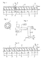
- Fig. 4 is an external view showing an example of a screw used in the conventional first-stage extruder.
- the screw having a total length L is constituted by a feed portion 2, a kneading portion 3, a metering portion 4, a vent portion 5, a kneading portion 3′, and a metering portion 4′ having lengths l2, l3, l4, l5, l′3, and l′4 respectively.
- a foaming-agent lead-in portion 6 is provided in a cylinder at a portion where the vent portion 5 of the screw 1 is positioned.
- the foaming-agent lead-in portion 6 has a structure such as a poppet valve, which is not illustrated in detail in the drawing, for preventing a plastic material in the cylinder from flowing back.
- the pellet-like plastic material supplied from a portion a of the cylinder is kneaded through the lengths l2, l3, and l4, further kneaded through the lengths l′3, and l′4 together with a foaming agent such as hydrocarbon chloride fluoride (flon) poured under volume-regulation at the vent portion 5, and then led into a second-stage extruder 10 (Fig. 3).
- a foaming agent such as hydrocarbon chloride fluoride (flon)
- the foaming agent and the mixed plastic material which are led into the second-stage extruder 10 are further kneaded so that the foaming agent is equally dispersed in the plastic material, and the thus kneaded foam plastic is applied onto a central conductor 16 as a coating therefor by a crosshead 15 constituted by a nipple and a die positioned at a top end of the second-stage extruder 10, thereby producing a high foam insulated wire-like body 17.
- the foaming agent performs an expanding action onto the plastic material, so that the conventional screw performs sufficient kneading.
- the present inventor has completed the present invention in which a plurality of stirring blades are provided in an extruder for highly foamed plastic material at its vent portion so that a high foam plastic material such as polyethylene or the like and an inert gas as a foaming agent can be evenly mixed with each other to thereby make it possible to stably extrude an insulator in an even, consistently foaming state.
- the extruder for highly foamed plastic material using an inert gas, such as a nitrogen gas, as a foaming agent for producing an electric wire insulated with high foam polyethylene having a foaming rate not lower than 70 % comprises: a cylinder; a foaming-agent lead-in portion provided in the cylinder at its middle portion so as to allow the foaming agent to enter the cylinder; a screw provided in the cylinder with a vent portion which may be tapered to provide a mixing space formed at a position where the foaming agent enters through the foaming-agent lead-in portion; and a plurality of stirring blades provided on the cylinder at the vent portion, the stirring blades having effective height extending to the vicinity of an inner wall of the cylinder.
- an inert gas such as a nitrogen gas
- the extruder for highly foamed plastic material mentioned above has a further feature in that the extruder is formed by a pair of first-stage and second-stage extruder units connected to each other, and in that the foaming-agent lead-in portion as defined above is provided in the first-stage extruder unit so that the foaming agent is led in at the middle portion of the first-stage extruder unit, and the screw having the shape and structure as defined above is provided in the first-stage extruder unit.
- Fig. 1 is a side sectional view showing an embodiment of the present invention.
- Fig. 1 shows an extruding screw of a first-stage extruder unit of an extruder for highly foamed plastic material in which an inert gas is used as a foaming agent.
- Fig. 2 is a sectional view taken on a line A-A of Fig. 1 and showing a structure of a vent portion of the screw 1.
- the present invention is proposed so as to solve the disadvantage in the conventional art and an object thereof is to provide an extruding screw 1 with a vent portion 5, which may be tapered and which is circumferentially provided with a plurality of stirring blades having an effective height extending to the vicinity of an inner wall of a cylinder 8.
- the stirring blades are provided in place of a flight of the screw threads in the vent portion 5.
- Fig. 3 is a schematic view showing another embodiment of the present invention of the extruder for highly foamed plastic material constituted by a pair of extruder units.
- An inert gas having predetermined pressure is led from an inert gas lead-in portion which is formed at the vent portion, the inert gas being fed into a completely melted plastic material through the lengths l2, l3, and l4 of the screw 1.
- the fed inert gas is physically mixed with the plastic material by a plurality of stirring blades 7 provided in the vent portion 5 with the stirring blades having an effective height extending to the vicinity of the inner wall of the cylinder 8.
- the mixture is further kneaded through the lengths l′3, and l′4, so that the inert gas is equally dispersed in the plastic material in the form of fine inert-gas bubbles to thereby obtain a stable extruding state in which an even, consistently foaming state is achieved.
- the extruding screw according to the present invention has an extrusion performance equivalent to that of the extruding method in which hydrocarbon chloride fluoride (flon) is used as a foaming agent.
- Low-density polyethylene, middle-density polyethylene, high-density polyethylene, polypropylene, butyl rubber, or the like, or a mixture of two or more kinds of the polyolefin-group resin can be used as the high-foam plastic material, and particularly polyethylene resin and polypropylene resin are preferrably used.
- the polyolefin resin may be mixed with a small quantity of other thermoplastic resin or rubber.
- the inert gas used as a foaming agent in the present invention may be, typically, nitrogen, argon, carbon dioxide, or the like. There is no specific requirement of which one so long as the inert gas is in a gaseous state under the conditions of temperature not lower than 100°C and pressure not higher than 30 kg/cm2.
- bubble nucleus forming agent such as azodicarbonamide or the like may be mixed with the foaming plastic material in advance.
- the flight of the screw thread at the vent portion is removed and a plurality of stirring blades with an effective height extending to the vicinity of the inner wall of the cylinder are provided around the circumference of the screw in a radial direction in place of the flight of screw thread, so that it becomes possible to physically mix and mull an inert gas and a high foam plastic material evenly with each other. Accordingly, a stable extruding state in which the foaming state is consistent can be obtained.
- the foaming agent such as the conventional hydrocarbon chloride fluoride or the like which may destroy the ozone layer in the air may be replaced with an inert gas which does not cause any environmental problem at all by replacing the conventional screw with a relatively inexpensive screw according to the present invention. Besides avoiding environmental problems, the cost of raw material can also be reduced.
- the present invention is effectively used in the cable producing field in which a high foam plastic material is applied as an insulator coating onto, for example, a central conductor of an insulated coaxial cable.
Landscapes
- Engineering & Computer Science (AREA)
- Mechanical Engineering (AREA)
- Extrusion Moulding Of Plastics Or The Like (AREA)
- Processes Specially Adapted For Manufacturing Cables (AREA)
- Manufacture Of Porous Articles, And Recovery And Treatment Of Waste Products (AREA)
- Molding Of Porous Articles (AREA)
Abstract
Description
- The present invention relates to an extruder for highly foamed plastic material for coating a central conductor of a coaxial insulated cable or the like with an insulator of for example a high foam plastic material, preferably polyethylene, having at least a 70% or more foaming rate.
- Conventionally, as the method for producing a coaxial insulated cable of the kind described above, there is a known technique in which hydrocarbon chloride fluoride (flon) or the like is used as a foaming agent in two extruders connected to each other. The foaming agent is led into the first-stage extruder at its middle portion so as to be kneaded with a plastic material such as polyethylene or the like, and then the kneaded plastic material is sent to the second-stage extruder so as to be further kneaded and the highly foamed plastic material is applied onto a central conductor as a coating.
- Fig. 4 (Prior Art) is an external view showing an example of a screw used in the conventional first-stage extruder.
- Here, the screw having a total length L is constituted by a
feed portion 2, a kneadingportion 3, ametering portion 4, avent portion 5, a kneadingportion 3′, and ametering portion 4′ having lengths l₂, l₃, l₄, l₅, l′₃, and l′₄ respectively. - A foaming-agent lead-in portion 6 is provided in a cylinder at a portion where the
vent portion 5 of thescrew 1 is positioned. The foaming-agent lead-in portion 6 has a structure such as a poppet valve, which is not illustrated in detail in the drawing, for preventing a plastic material in the cylinder from flowing back. - The pellet-like plastic material supplied from a portion a of the cylinder is kneaded through the lengths l₂, l₃, and l₄, further kneaded through the lengths l′₃, and
l′ ₄ together with a foaming agent such as hydrocarbon chloride fluoride (flon) poured under volume-regulation at thevent portion 5, and then led into a second-stage extruder 10 (Fig. 3). - As portrayed in a schematic view in Fig. 3, the foaming agent and the mixed plastic material which are led into the second-
stage extruder 10 are further kneaded so that the foaming agent is equally dispersed in the plastic material, and the thus kneaded foam plastic is applied onto acentral conductor 16 as a coating therefor by acrosshead 15 constituted by a nipple and a die positioned at a top end of the second-stage extruder 10, thereby producing a high foam insulated wire-like body 17. - Conventionally, in extruding a plastic material such as high foam polyethylene or the like in which hydrocarbon chloride fluoride (flon) or the like is used as a foaming agent, the foaming agent performs an expanding action onto the plastic material, so that the conventional screw performs sufficient kneading.
- Recently, however, the theory has been advocated that hydrocarbon chloride fluoride, or flon, destroys the ozone layer, causing destruction of the ozone layer on a world-wide scale. Thus, in achieving a method for extruding a high foam plastic material using an inert gas (for example, a nitrogen gas) as a foaming agent, a conventional high foam extruding method cannot be used because a a stable consistent foaming state is not achieved. When such a method is used for extruding a high foam plastic material having an inert gas, both the electrostatic capacitance required as a characteristic of cables and the outer diameter of the cables vary extremely. Accordingly, an extrusion method for extruding high foam plastic material using an inert gas as a foaming agent and in which the foaming state is consistent and stable has been required.
- In order to solve the above problems, as a result of various investigations, the present inventor has completed the present invention in which a plurality of stirring blades are provided in an extruder for highly foamed plastic material at its vent portion so that a high foam plastic material such as polyethylene or the like and an inert gas as a foaming agent can be evenly mixed with each other to thereby make it possible to stably extrude an insulator in an even, consistently foaming state.
- That is, according to the present invention, the extruder for highly foamed plastic material using an inert gas, such as a nitrogen gas, as a foaming agent for producing an electric wire insulated with high foam polyethylene having a foaming rate not lower than 70 %, comprises: a cylinder; a foaming-agent lead-in portion provided in the cylinder at its middle portion so as to allow the foaming agent to enter the cylinder; a screw provided in the cylinder with a vent portion which may be tapered to provide a mixing space formed at a position where the foaming agent enters through the foaming-agent lead-in portion; and a plurality of stirring blades provided on the cylinder at the vent portion, the stirring blades having effective height extending to the vicinity of an inner wall of the cylinder.
- The extruder for highly foamed plastic material mentioned above has a further feature in that the extruder is formed by a pair of first-stage and second-stage extruder units connected to each other, and in that the foaming-agent lead-in portion as defined above is provided in the first-stage extruder unit so that the foaming agent is led in at the middle portion of the first-stage extruder unit, and the screw having the shape and structure as defined above is provided in the first-stage extruder unit.
-
- Fig. 1 is a side section showing an extruding screw of a first-stage extruder unit of an extruder for highly foamed plastic material, as an embodiment of the present invention;
- Fig. 2 is a sectional view taken on a line A-A of Fig. 1;
- Fig. 3 is a schematic view showing another embodiment of the present invention of the extruder for highly foamed plastic material constituted by a pair of extruder units; and
- Fig. 4 (Prior Art) is a side section showing an example of a conventional extruding screw.
- Fig. 1 is a side sectional view showing an embodiment of the present invention. In particular, Fig. 1 shows an extruding screw of a first-stage extruder unit of an extruder for highly foamed plastic material in which an inert gas is used as a foaming agent.
- Fig. 2 is a sectional view taken on a line A-A of Fig. 1 and showing a structure of a vent portion of the
screw 1. - As shown in Figs. 1 and 2, the present invention is proposed so as to solve the disadvantage in the conventional art and an object thereof is to provide an
extruding screw 1 with avent portion 5, which may be tapered and which is circumferentially provided with a plurality of stirring blades having an effective height extending to the vicinity of an inner wall of a cylinder 8. The stirring blades are provided in place of a flight of the screw threads in thevent portion 5. - Fig. 3 is a schematic view showing another embodiment of the present invention of the extruder for highly foamed plastic material constituted by a pair of extruder units.
- Next, the operation will be described. An inert gas having predetermined pressure is led from an inert gas lead-in portion which is formed at the vent portion, the inert gas being fed into a completely melted plastic material through the lengths l₂, l₃, and l₄ of the
screw 1. The fed inert gas is physically mixed with the plastic material by a plurality of stirringblades 7 provided in thevent portion 5 with the stirring blades having an effective height extending to the vicinity of the inner wall of the cylinder 8. The mixture is further kneaded through the lengths l′₃, and l′₄, so that the inert gas is equally dispersed in the plastic material in the form of fine inert-gas bubbles to thereby obtain a stable extruding state in which an even, consistently foaming state is achieved. - Here, variations in the characteristics of cables coated with a high foam insulator depending on the difference in screw structure are as shown in the following Table 1.

- It is apparent from the result of Table 1 that the extruding screw according to the present invention has an extrusion performance equivalent to that of the extruding method in which hydrocarbon chloride fluoride (flon) is used as a foaming agent.
- Low-density polyethylene, middle-density polyethylene, high-density polyethylene, polypropylene, butyl rubber, or the like, or a mixture of two or more kinds of the polyolefin-group resin can be used as the high-foam plastic material, and particularly polyethylene resin and polypropylene resin are preferrably used.
- Further, as the high foam plastic material according to the present invention, the polyolefin resin may be mixed with a small quantity of other thermoplastic resin or rubber.
- The inert gas used as a foaming agent in the present invention may be, typically, nitrogen, argon, carbon dioxide, or the like. There is no specific requirement of which one so long as the inert gas is in a gaseous state under the conditions of temperature not lower than 100°C and pressure not higher than 30 kg/cm².
- In foaming, a small amount of bubble nucleus forming agent such as azodicarbonamide or the like may be mixed with the foaming plastic material in advance.
- As described above, according to the present invention, in the extruder for extruding the high foam plastic material using an inert gas as a foaming agent, the flight of the screw thread at the vent portion is removed and a plurality of stirring blades with an effective height extending to the vicinity of the inner wall of the cylinder are provided around the circumference of the screw in a radial direction in place of the flight of screw thread, so that it becomes possible to physically mix and mull an inert gas and a high foam plastic material evenly with each other. Accordingly, a stable extruding state in which the foaming state is consistent can be obtained.
- According to the present invention, it is possible to obtain extremely good effects in that the foaming agent such as the conventional hydrocarbon chloride fluoride or the like which may destroy the ozone layer in the air may be replaced with an inert gas which does not cause any environmental problem at all by replacing the conventional screw with a relatively inexpensive screw according to the present invention. Besides avoiding environmental problems, the cost of raw material can also be reduced.
- Accordingly, the present invention is effectively used in the cable producing field in which a high foam plastic material is applied as an insulator coating onto, for example, a central conductor of an insulated coaxial cable.
- While this invention has been described in connection with what is presently considered to be the most practical and preferred embodiment, it is to be understood that the invention is not limited to the disclosed embodiment, but, on the contrary, is intended to cover various modifications and equivalent arrangements included within the spirit and scope of the appended claims.
Claims (3)
- An extruder for highly foamed plastic material using an inert gas as a foaming agent comprising:
a cylinder having a foaming-agent lead-in portion through which said foaming agent enters into said cylinder, said cylinder defining a cavity;
a screw extending through said cavity for propelling plastic material through said cavity as said screw rotates, said screw having a vent portion; and
a plurality of stirring blades extending radially from said vent portion adjacent to said lead-in portion for stirring said foaming agent into said plastic material as said plastic material is moved through said cavity. - An extruder for highly foamed plastic material according to claim 1, wherein said vent portion comprises a tapered section of said screw from which a flight of screw thread is removed to form a mixing space and said stirring blades extend radially from around the circumference of said screw toward an inside surface of said cylinder.
- An extruder for highly foamed plastic material comprising:
a first-stage extruder unit including:
a first cylinder having a foaming-agent lead-in portion through which said foaming agent enters into said first cylinder, said first cylinder defining a cavity;
a first screw extending through said first cavity for propelling plastic material through said first cavity as said first screw rotates, said first screw having a vent portion; and
a plurality of stirring blades extending radially from said vent portion adjacent to said lead-in portion for stirring said foaming agent into said plastic material as said plastic material is moved through said first cavity; and
a second-stage extruder unit, connected to said first-stage extruder unit, for receiving a mixture of said plastic material and said foaming agent and further propelling and mixing said mixture, including:
a second cylinder, said second cylinder defining a second cavity;
a second screw extending through said second cavity for propelling said mixture through said second cavity and further mixing said mixture as said second screw rotates; and
a combination of a nipple and a die, located at the end of said second-stage extruder unit, for receiving said mixture from said second-stage extruder unit and applying aid mixture onto a central conductor.
Applications Claiming Priority (2)
| Application Number | Priority Date | Filing Date | Title |
|---|---|---|---|
| JP2028428A JPH03233814A (en) | 1990-02-09 | 1990-02-09 | High foam insulation extruder |
| JP28428/90 | 1990-02-09 |
Publications (3)
| Publication Number | Publication Date |
|---|---|
| EP0441762A2 true EP0441762A2 (en) | 1991-08-14 |
| EP0441762A3 EP0441762A3 (en) | 1991-10-16 |
| EP0441762B1 EP0441762B1 (en) | 1997-05-14 |
Family
ID=12248390
Family Applications (1)
| Application Number | Title | Priority Date | Filing Date |
|---|---|---|---|
| EP91850029A Expired - Lifetime EP0441762B1 (en) | 1990-02-09 | 1991-02-08 | Extruder for highly foamed plastic material |
Country Status (5)
| Country | Link |
|---|---|
| US (1) | US5234324A (en) |
| EP (1) | EP0441762B1 (en) |
| JP (1) | JPH03233814A (en) |
| AT (1) | ATE152960T1 (en) |
| FI (1) | FI910638A7 (en) |
Cited By (6)
| Publication number | Priority date | Publication date | Assignee | Title |
|---|---|---|---|---|
| EP0597375A1 (en) * | 1992-11-13 | 1994-05-18 | Union Industrie Comprimierter Gase Gmbh Nfg. Kg | Manufacturing of expanded polymers |
| WO1998008667A3 (en) * | 1996-08-27 | 1998-05-14 | Trexel Inc | Method and apparatus for microcellular polymer extrusion |
| US6005013A (en) * | 1995-08-14 | 1999-12-21 | Massachusetts Institute Of Technology | Gear throttle as a nucleation device in a continuous microcellular extrusion system |
| US6602063B1 (en) * | 2000-07-21 | 2003-08-05 | Trexel, Inc. | Discontinuous blowing agent delivery system and method |
| US6884377B1 (en) | 1996-08-27 | 2005-04-26 | Trexel, Inc. | Method and apparatus for microcellular polymer extrusion |
| WO2022214723A1 (en) * | 2021-04-07 | 2022-10-13 | Focke Meler Gluing Solutions, S.A. | Machine for applying hot-melt products |
Families Citing this family (9)
| Publication number | Priority date | Publication date | Assignee | Title |
|---|---|---|---|---|
| US6113375A (en) * | 1998-11-09 | 2000-09-05 | Fogarty; James | Thermoplastic foam extrusion assembly |
| US6432337B1 (en) * | 1998-11-09 | 2002-08-13 | James D. Fogarty | Thermoplastic foam extrusion |
| GB9908099D0 (en) * | 1999-04-12 | 1999-06-02 | Gay Geoffrey N W | Air cleaning collection device |
| JP4276754B2 (en) * | 1999-11-11 | 2009-06-10 | 株式会社日本製鋼所 | Thermoplastic resin foam molding method |
| MX2009009705A (en) * | 2007-03-10 | 2009-10-30 | Cool Options Inc | Screw design and method for metal injection molding. |
| JP4939623B2 (en) * | 2010-03-30 | 2012-05-30 | 株式会社日本製鋼所 | Injection molding machine screw and injection molding machine |
| EP4108406B1 (en) * | 2015-07-08 | 2024-04-24 | Maxell, Ltd. | Process and device for producing molded foam |
| KR102185341B1 (en) * | 2016-03-15 | 2020-12-01 | 마쿠세루 가부시키가이샤 | Method and apparatus for manufacturing foam molded body |
| CN106448920B (en) * | 2016-08-31 | 2024-12-06 | 池州市谦跃信息技术有限公司 | An extrusion screw for conveying high-temperature PA material of three-layer insulation wire |
Family Cites Families (23)
| Publication number | Priority date | Publication date | Assignee | Title |
|---|---|---|---|---|
| GB989856A (en) * | 1961-06-02 | 1965-04-22 | Monsanto Co | Extrusion process and apparatus |
| US3160688A (en) * | 1961-06-02 | 1964-12-08 | Monsanto Co | Extrusion process |
| DE1201041B (en) * | 1962-07-10 | 1965-09-16 | Kloeckner Humboldt Deutz Ag | Screw extruder for plastic masses, e.g. B. thermoplastics |
| BE638078A (en) * | 1962-10-03 | 1964-04-01 | ||
| US3374300A (en) * | 1963-10-12 | 1968-03-19 | Azuma Kimikazu | Process and apparatus for the continuous production of polystyrenic foam materials |
| US3287477A (en) * | 1964-11-12 | 1966-11-22 | Koppers Co Inc | Process and apparatus for extruding a foamed plastic |
| GB1202301A (en) * | 1967-07-29 | 1970-08-12 | Werner & Pfleiderer | A machine for continuously mixing blending and plasticising synthetic plastics compositions |
| US3843757A (en) * | 1967-11-15 | 1974-10-22 | Hercules Inc | Process for extruding foamed thermoplastics by utilizing an intermeshing co-rotating twin screw extruder |
| GB1315661A (en) * | 1969-06-18 | 1973-05-02 | British Insulated Callenders | Plastics extrusion process and apparatus |
| US3806099A (en) * | 1969-06-18 | 1974-04-23 | H Gallard | Plastics extrusion apparatus |
| JPS5513895B2 (en) * | 1973-01-13 | 1980-04-12 | ||
| GB1485587A (en) * | 1974-01-22 | 1977-09-14 | Furukawa Electric Co Ltd | Process of producing a foamed thermoplastics resin articl |
| CA1058716A (en) * | 1975-06-05 | 1979-07-17 | Steve A. Fox | Coaxial cable with improved properties and process of making same |
| JPS5249267A (en) * | 1975-10-17 | 1977-04-20 | Japan Steel Works Ltd | Degassing modifying extruder |
| GB1511706A (en) * | 1975-11-07 | 1978-05-24 | Ici Ltd | Removal of residual solvent from chlorinated polymers |
| DE2910965C2 (en) * | 1979-03-21 | 1985-05-02 | kabelmetal electro GmbH, 3000 Hannover | Spray device for applying a cover made of foamed plastic to elongated material |
| JPS5617237A (en) * | 1979-07-21 | 1981-02-19 | Matsushita Electric Works Ltd | Screw for extruder |
| JPS6054851B2 (en) * | 1979-10-23 | 1985-12-02 | 住友電気工業株式会社 | foam extrusion equipment |
| DE3316838C2 (en) * | 1983-05-07 | 1986-08-21 | Hermann Berstorff Maschinenbau Gmbh, 3000 Hannover | Tandem extruder system for the production of a foamed material web from thermoplastic material, in particular from polystyrene |
| CA1255866A (en) * | 1985-07-24 | 1989-06-20 | Hiromu Fujisaki | Method and apparatus for production of foamed thermoplastic material |
| US4746478A (en) * | 1985-07-24 | 1988-05-24 | Sekisui Kaseihin Kogyo Kabushiki Kaisha | Method and apparatus for production of foamed thermoplastic material |
| GB2202539B (en) * | 1987-01-28 | 1991-07-03 | Du Pont Canada | Polyolefin concentrate |
| DE3841729C1 (en) * | 1988-12-10 | 1990-03-01 | Hermann Berstorff Maschinenbau Gmbh, 30627 Hannover | Single or twin screw extruders for degassing thermoplastic melts |
-
1990
- 1990-02-09 JP JP2028428A patent/JPH03233814A/en active Pending
-
1991
- 1991-02-08 US US07/653,089 patent/US5234324A/en not_active Expired - Lifetime
- 1991-02-08 AT AT91850029T patent/ATE152960T1/en not_active IP Right Cessation
- 1991-02-08 FI FI910638A patent/FI910638A7/en not_active Application Discontinuation
- 1991-02-08 EP EP91850029A patent/EP0441762B1/en not_active Expired - Lifetime
Cited By (9)
| Publication number | Priority date | Publication date | Assignee | Title |
|---|---|---|---|---|
| EP0597375A1 (en) * | 1992-11-13 | 1994-05-18 | Union Industrie Comprimierter Gase Gmbh Nfg. Kg | Manufacturing of expanded polymers |
| US6005013A (en) * | 1995-08-14 | 1999-12-21 | Massachusetts Institute Of Technology | Gear throttle as a nucleation device in a continuous microcellular extrusion system |
| WO1998008667A3 (en) * | 1996-08-27 | 1998-05-14 | Trexel Inc | Method and apparatus for microcellular polymer extrusion |
| US6284810B1 (en) | 1996-08-27 | 2001-09-04 | Trexel, Inc. | Method and apparatus for microcellular polymer extrusion |
| US6884377B1 (en) | 1996-08-27 | 2005-04-26 | Trexel, Inc. | Method and apparatus for microcellular polymer extrusion |
| US6602063B1 (en) * | 2000-07-21 | 2003-08-05 | Trexel, Inc. | Discontinuous blowing agent delivery system and method |
| WO2022214723A1 (en) * | 2021-04-07 | 2022-10-13 | Focke Meler Gluing Solutions, S.A. | Machine for applying hot-melt products |
| ES2925824A1 (en) * | 2021-04-07 | 2022-10-19 | Focke Meler Gluing Solutions S A | MACHINE FOR THE APPLICATION OF THERMOFUSE PRODUCTS |
| US12629878B2 (en) | 2021-04-07 | 2026-05-19 | Focke Meler Gluing Solutions, S.A. | Machine for applying hot-melt products |
Also Published As
| Publication number | Publication date |
|---|---|
| ATE152960T1 (en) | 1997-05-15 |
| JPH03233814A (en) | 1991-10-17 |
| FI910638L (en) | 1991-08-10 |
| US5234324A (en) | 1993-08-10 |
| EP0441762B1 (en) | 1997-05-14 |
| FI910638A0 (en) | 1991-02-08 |
| FI910638A7 (en) | 1991-08-10 |
| EP0441762A3 (en) | 1991-10-16 |
Similar Documents
| Publication | Publication Date | Title |
|---|---|---|
| US5234324A (en) | Extruder for highly foamed plastic material having a reduced diameter mixing space for introducing an inert foaming agent | |
| US4250132A (en) | Material and apparatus for extruding a crosslinked polyolefin product | |
| US3947173A (en) | Apparatus for extruding concentric plastic sheaths | |
| US4169679A (en) | Apparatus for the extrusion of cellular thermoplastic material | |
| US3956438A (en) | Process for extruding a partially foamed thermoplastic product | |
| US4302409A (en) | Method for the extrusion of thermoplastic material composites | |
| US4182601A (en) | Extrusion apparatus | |
| US2848739A (en) | Methods of and apparatus for making cellular plastic products | |
| US2653351A (en) | Apparatus for advancing and working elastomer compounds | |
| US3782870A (en) | Apparatus for extruding a partially foamed thermoplastic product | |
| US2766479A (en) | Apparatus for extruding cellular plastics | |
| CA1293844C (en) | Screw type extruder with flow chambers externally and internally of screw | |
| DE2504702A1 (en) | PROCESS FOR MANUFACTURING A PRODUCT CONTAINING FOAM AND DEVICE FOR CARRYING OUT THE PROCESS | |
| US3903233A (en) | Method of and apparatus for extruding concentric plastic sheaths | |
| US2835927A (en) | Methods of producing cellular plastics | |
| US2960482A (en) | Method of making plastic articles | |
| US2750627A (en) | Apparatus for working and advancing a plastic material | |
| US6652786B2 (en) | Method for manufacturing coaxial wire with foamed insulation | |
| GB1564410A (en) | Method and apparatus for the production of cellular thermoplastic material | |
| JPH081070Y2 (en) | Resin extrusion equipment | |
| JPH0578407B2 (en) | ||
| EP0413255B1 (en) | Method for manufacturing a foam-insulated electric wire | |
| JPS6054851B2 (en) | foam extrusion equipment | |
| JPH0117450B2 (en) | ||
| GB1590381A (en) | Extrusion apparatus and method |
Legal Events
| Date | Code | Title | Description |
|---|---|---|---|
| PUAI | Public reference made under article 153(3) epc to a published international application that has entered the european phase |
Free format text: ORIGINAL CODE: 0009012 |
|
| AK | Designated contracting states |
Kind code of ref document: A2 Designated state(s): AT CH LI SE |
|
| PUAL | Search report despatched |
Free format text: ORIGINAL CODE: 0009013 |
|
| AK | Designated contracting states |
Kind code of ref document: A3 Designated state(s): AT CH LI SE |
|
| 17P | Request for examination filed |
Effective date: 19920323 |
|
| 17Q | First examination report despatched |
Effective date: 19940513 |
|
| GRAG | Despatch of communication of intention to grant |
Free format text: ORIGINAL CODE: EPIDOS AGRA |
|
| GRAH | Despatch of communication of intention to grant a patent |
Free format text: ORIGINAL CODE: EPIDOS IGRA |
|
| GRAH | Despatch of communication of intention to grant a patent |
Free format text: ORIGINAL CODE: EPIDOS IGRA |
|
| GRAA | (expected) grant |
Free format text: ORIGINAL CODE: 0009210 |
|
| AK | Designated contracting states |
Kind code of ref document: B1 Designated state(s): AT CH LI SE |
|
| REF | Corresponds to: |
Ref document number: 152960 Country of ref document: AT Date of ref document: 19970515 Kind code of ref document: T |
|
| REG | Reference to a national code |
Ref country code: CH Ref legal event code: EP |
|
| REG | Reference to a national code |
Ref country code: CH Ref legal event code: NV Representative=s name: BOVARD AG PATENTANWAELTE |
|
| PLBE | No opposition filed within time limit |
Free format text: ORIGINAL CODE: 0009261 |
|
| STAA | Information on the status of an ep patent application or granted ep patent |
Free format text: STATUS: NO OPPOSITION FILED WITHIN TIME LIMIT |
|
| 26N | No opposition filed | ||
| PGFP | Annual fee paid to national office [announced via postgrant information from national office to epo] |
Ref country code: SE Payment date: 19990204 Year of fee payment: 9 |
|
| PGFP | Annual fee paid to national office [announced via postgrant information from national office to epo] |
Ref country code: AT Payment date: 19990211 Year of fee payment: 9 |
|
| PGFP | Annual fee paid to national office [announced via postgrant information from national office to epo] |
Ref country code: CH Payment date: 19990226 Year of fee payment: 9 |
|
| PG25 | Lapsed in a contracting state [announced via postgrant information from national office to epo] |
Ref country code: AT Free format text: LAPSE BECAUSE OF NON-PAYMENT OF DUE FEES Effective date: 20000208 |
|
| PG25 | Lapsed in a contracting state [announced via postgrant information from national office to epo] |
Ref country code: SE Free format text: LAPSE BECAUSE OF NON-PAYMENT OF DUE FEES Effective date: 20000209 |
|
| PG25 | Lapsed in a contracting state [announced via postgrant information from national office to epo] |
Ref country code: LI Free format text: LAPSE BECAUSE OF NON-PAYMENT OF DUE FEES Effective date: 20000229 Ref country code: CH Free format text: LAPSE BECAUSE OF NON-PAYMENT OF DUE FEES Effective date: 20000229 |
|
| EUG | Se: european patent has lapsed |
Ref document number: 91850029.9 |
|
| REG | Reference to a national code |
Ref country code: CH Ref legal event code: PL |