EP0441770A2 - Dispositif de mesure de densité - Google Patents
Dispositif de mesure de densité Download PDFInfo
- Publication number
- EP0441770A2 EP0441770A2 EP91890020A EP91890020A EP0441770A2 EP 0441770 A2 EP0441770 A2 EP 0441770A2 EP 91890020 A EP91890020 A EP 91890020A EP 91890020 A EP91890020 A EP 91890020A EP 0441770 A2 EP0441770 A2 EP 0441770A2
- Authority
- EP
- European Patent Office
- Prior art keywords
- housing
- capacitance
- measuring device
- liquid
- examined
- Prior art date
- Legal status (The legal status is an assumption and is not a legal conclusion. Google has not performed a legal analysis and makes no representation as to the accuracy of the status listed.)
- Withdrawn
Links
- 239000007788 liquid Substances 0.000 claims abstract description 52
- 238000012544 monitoring process Methods 0.000 claims abstract description 13
- 239000000725 suspension Substances 0.000 claims description 7
- 238000013016 damping Methods 0.000 claims description 6
- 239000003990 capacitor Substances 0.000 claims description 5
- 239000000446 fuel Substances 0.000 abstract description 19
- 238000002485 combustion reaction Methods 0.000 abstract description 4
- 238000013461 design Methods 0.000 description 6
- 238000005259 measurement Methods 0.000 description 6
- 230000001419 dependent effect Effects 0.000 description 4
- 238000001739 density measurement Methods 0.000 description 3
- 238000010586 diagram Methods 0.000 description 2
- 239000002828 fuel tank Substances 0.000 description 2
- 239000011521 glass Substances 0.000 description 2
- 238000002347 injection Methods 0.000 description 2
- 239000007924 injection Substances 0.000 description 2
- 230000035945 sensitivity Effects 0.000 description 2
- 230000001133 acceleration Effects 0.000 description 1
- 230000000903 blocking effect Effects 0.000 description 1
- 238000011109 contamination Methods 0.000 description 1
- 230000007423 decrease Effects 0.000 description 1
- 239000002283 diesel fuel Substances 0.000 description 1
- 230000000694 effects Effects 0.000 description 1
- 230000007613 environmental effect Effects 0.000 description 1
- 238000011156 evaluation Methods 0.000 description 1
- 230000005284 excitation Effects 0.000 description 1
- 238000007654 immersion Methods 0.000 description 1
- 238000000034 method Methods 0.000 description 1
- 239000000203 mixture Substances 0.000 description 1
- 239000002245 particle Substances 0.000 description 1
- 230000008092 positive effect Effects 0.000 description 1
- 230000006641 stabilisation Effects 0.000 description 1
- 238000011105 stabilization Methods 0.000 description 1
Images


Classifications
-
- G—PHYSICS
- G01—MEASURING; TESTING
- G01N—INVESTIGATING OR ANALYSING MATERIALS BY DETERMINING THEIR CHEMICAL OR PHYSICAL PROPERTIES
- G01N9/00—Investigating density or specific gravity of materials; Analysing materials by determining density or specific gravity
- G01N9/10—Investigating density or specific gravity of materials; Analysing materials by determining density or specific gravity by observing bodies wholly or partially immersed in fluid materials
- G01N9/12—Investigating density or specific gravity of materials; Analysing materials by determining density or specific gravity by observing bodies wholly or partially immersed in fluid materials by observing the depth of immersion of the bodies, e.g. hydrometers
- G01N9/14—Investigating density or specific gravity of materials; Analysing materials by determining density or specific gravity by observing bodies wholly or partially immersed in fluid materials by observing the depth of immersion of the bodies, e.g. hydrometers the body being built into a container
Definitions
- the invention relates to a measuring device for determining the density of liquids, with a buoyancy body of known specific weight immersed in the liquid to be examined, the buoyancy of which is balanced by a loading device with progressively acting counterforce and with a measuring arrangement for the vertical position of the buoyancy body, which is a according to this position in its capacitance variable capacity and an arrangement for monitoring this, serving as a measure of the density capacitance value.
- Measuring devices for determining the density of liquids that work using the buoyancy of a measuring body are known, for example, in the form of the hydrometer or also the Mohr-Westphal scale and allow, using the Archimedes' principle, relatively simple and precise density determinations under certain standardized conditions. Problems with the known designs of the devices mentioned, on the one hand, the reading or further use of the measurement results and, on the other hand, measurements on liquids whose density changes over time, so that, for example, the measurement of flowing liquids, whose density change is to be monitored over time, does not or only with disproportionate effort is possible.
- a buoyancy-dependent measuring device of the type mentioned at the outset has been designed such that the liquid to be examined is a sample container Flows through the top, the buoyancy body immersed in the liquid via a suspension wire with a arranged outside the sample container loading device is balanced.
- the suspension wire is guided regardless of the buoyancy-dependent position of the buoyancy body with a constant radius to the pivot point of the loading device, the suspension of a counterweight on the loading device is carried out so that the effective lever arm increases linearly with increasing immersion depth of the buoyancy body, so that this with its vertical position in the liquid gives a measure of the respective density of the liquid.
- the known density can also be determined in this known device by means of a variable capacitor adjusted with the loading device or its capacitance.
- a device for measuring the density in which a measuring spindle is immersed in a measuring chamber, a proximity switch being attached below the measuring spindle, which emits an analog signal proportional to the density of the liquid.
- the continuous monitoring or determination of the density of the fuel supplied to an internal combustion engine has become essential in recent years, since it is also used as a parameter in electronically controlled injection systems can be used.
- lighter fuel is used specifically in the northern countries of Europe than in the southern countries.
- the so-called blocking amount corresponds to "full throttle”
- a density monitor could be used to adapt the maximum injection quantity to the fuel in the tank.
- the known arrangements mentioned are not suitable for being carried along and for operation in a truck, for example.
- An electronic density measuring device has become known some time ago, in which the liquid to be examined is sucked into an essentially U-shaped glass tube, which is used as a resonator and stimulates mechanical vibrations in the kHz range. The resonance frequency is then a measure of the density of the liquid in the glass tube.
- the object of the present invention is to design a simple measuring device of the type mentioned at the outset in such a way that the disadvantages of the known device of this type are avoided and that, in particular, the density of liquids is inexpensive and therefore also suitable for mass use can be reliably monitored even under relatively rough mechanical environmental conditions, such as changing accelerations, vibrations and the like.
- the loading device has a spring acting on the buoyancy body, which is attached to a housing enclosing the buoyancy body and the spring and filled with the electrically non-conductive liquid to be examined, and in that the capacitance is on the one hand by the buoyancy body and on the other hand is formed by the housing.
- the buoyancy body together with the loading device (this always includes the device providing the counterforce to the buoyancy) on the one hand and variable capacity for monitoring the position of the buoyancy body on the other hand is accommodated in the housing also containing the liquid to be examined, which is a very compact and robust Structure of the measuring device results.
- the buoyancy body can also be provided with damping vanes if necessary to dampen undesired movements.
- the entire arrangement can be produced extremely inexpensively and can be arranged, for example, in the region of the outlet of the fuel tank of a motor vehicle or the like and flowed through by the fuel to be examined.
- the spring is formed by a leaf spring and that the housing has a support body holding the leaf spring, which surrounds the leaf spring together with the buoyancy body in a U-shape and in the region of an electrode of the capacitance which is arranged on the buoyancy body , conductive flag has at least one counter electrode.
- the outside of the carrier body is surrounded by a finely perforated cover, preferably a fine-mesh, electrically conductive grid. It is therefore a constant exchange or flow through the liquid to be examined enables and at the same time ensures that wave movements or higher flow velocities in the liquid to be examined, which are caused by other external circumstances, cannot have any effect on the movement or position of the buoyancy body. At the same time, contamination by floating particles in the liquid to be examined is avoided and electrical shielding of the variable capacitance is effected.
- two counter electrodes of the capacitors can be arranged on the housing or on the carrier body, the difference in the capacitance values being determinable as a measure of the density. The density determination is thus traced back to the more sensitive determination of a difference in capacitance values, which allows the measurement accuracy to be increased in the simplest way.
- the spring of the loading device can be formed by a helical spring which is suspended in the upper region of the housing and carries the buoyancy body, the bottom of the capacitance forming the counter electrode of the up to the inlet and outlet for the liquid to be examined closed housing is designed as a spherical cap with a center in the suspension of the coil spring.
- the inlet of the liquid to be examined can preferably be arranged in the bottom region of the housing, preferably oriented tangentially, the outlet lying in the uppermost region of the housing. In this way, no air bubbles directly influencing the variable capacity or the position of the buoyancy body can form or hold in the housing. Because of the large flow cross-section in the lower area of the housing, the inflow speed is also so low that the pendulum-suspended buoyancy body cannot be disturbed by the flow.
- the bottom area is permeable to sieves and immediately forms the inlet, which likewise has positive effects with regard to any avoidance of disruptive movements of the buoyancy body.
- a compensation electrode which is fixed relative to the housing is arranged in the housing to take into account the dependence of the measured capacitance value on the dielectric constant of the liquid to be examined and is connected to the arrangement for capacitance monitoring.
- the dielectric constant which may change with the fuel density, for example, or its influence on the measured capacitance value can also be taken into account.
- the capacitance between the buoyancy body and the housing is part of a feedback, capacitive bridge circuit, which allows simple measurements of the variable capacitance value and thus the density to be determined.
- At least one compensation capacitance can be arranged in the half of the measuring bridge containing the capacitance value (s) which can vary in capacitance value. Since the variable capacity according to the invention lies entirely in the liquid to be examined, its value - as mentioned - depends not only on the buoyancy-dependent deflection of the buoyancy body, but also on the value E of the examined liquid. The sensitivity (output voltage difference per density difference) would be greater for a liquid with a higher E value. This influence of the E value can be eliminated by means of the above-mentioned, if necessary also multi-part, compensation capacity.
- the capacitance between the buoyancy body and the housing can also be a frequency-influencing component of an oscillator circuit, thus determining the one to be determined or monitoring density can be observed or derived from the frequency detuning.
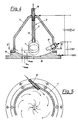
- the measuring device for determining the density of liquids shown in its entirety essentially in FIGS. 1 to 3, has a buoyancy body 1 of known specific weight immersed in the liquid to be examined, the buoyancy of which (in the installed state in the liquid not shown here in the Drawing plane acting vertically upward) is balanced by a loading device 2 with a progressively acting counterforce, and a measuring arrangement 3 for the vertical position of the buoyancy body 1.
- the measuring arrangement 3 has a capacitance C1, C2 (differential capacitance) which varies according to the position of the buoyant body 1 in its capacitance value (c I , c II ) and an arrangement 4 shown in FIG. 3 for monitoring these capacitance values c serving as a measure of the density I , c II on.
- the loading device 2 has a spring 5 acting on the buoyancy body 1, which is formed according to FIG. 1 by a leaf spring 6 and is fastened to a housing 7 enclosing the buoyancy body 1 and the spring 5 and filled with the electrically non-conductive liquid to be examined.
- the housing 7 has a carrier body 8 holding the leaf spring 6, which surrounds the leaf spring 6 together with the buoyancy body 1 in a U-shape and in the area of a conductive flag 9 arranged on the buoyancy body 1 and forming an electrode of the capacitance C1, C2, two counter electrodes 10, 11 having.
- the capacitance C1, C2 is thus defined on the one hand by the buoyancy body 1 or its lug 9 and on the other hand by the housing 7 or the counter electrodes 10, 11 in the form of the difference between the capacitance values c I , c II of the capacitances C1 on the one hand and C2 on the other hand can advantageously be determined via the circuit arrangement shown in FIG. 3, to which reference is also made below.
- the carrier body 8 of the housing 7 is surrounded on the outside according to FIG. 1 with a finely perforated cover 12 in the form of a fine-meshed, electrically conductive grid, so that in particular the interior housing the buoyancy body 1 and the spring 5 is protected against wave movements of the liquid to be examined , whereby the constant exchange of this liquid remains guaranteed.
- the cover 12 completely surrounds the electrically non-conductive carrier body 8, so that there is also an electrical shield for the internal counter electrodes 10, 11 and the flag 9 or the capacitances formed thereby.
- the two capacitances C1 and C2 are part of a feedback capacitive bridge circuit which is supplied with two oppositely equal voltages U9 and U10 via a square wave oscillator, not shown.
- C5 C6 (e.g. 10pF)
- C3 C4 (e.g. 10pF)
- the capacitance values c I , c II of C1 and C2 are of the order of a few pF, with C2 being a trimmer capacitor.
- the bridge is connected to the square wave voltages U9 and U10 (Fig. 3a).
- U9 has a positive and U10 a negative edge.
- the emitter current generated between t1 and t2 gives the collector current, which is smoothed via C7 and causes the direct current I1.
- the elements of the circuit are designed so that U5 (and therefore also U6) is in the modulation range of OA1.
- the voltage U1 increases at time t1 compared to the value previously described. This increases the emitter current and also the collector current, the current I1 smoothed via C7 also becomes greater than I2, as a result of which an input differential voltage is present at OA1. Its output U7 becomes more negative and because of the inverter OA2 U8 becomes more positive. As a result, the emitter potential of T1 is raised via R8, and that of T2 is lowered via R7. The emitter current of t1 is thereby reduced, that of T2 is increased. Because of the high no-load gain of OA1, U7 and U8 are changed until the averaged currents I1 and I2 are the same size again and the bridge thus again reaches a stable state.
- the voltage difference between U7 and U8 required for this stable state is a measure of the capacitance difference between c I and c II and thus represents the position of the buoyancy body.
- the useful signal is the voltage difference between U7 and U8, whereby the smallest changes in capacitance are converted into large voltage swings.
- the capacitors C3 and C4 reduce the influence of the dielectric constant E of the liquid to be measured, that is to say of the fuel to be measured. Since the capacities C1 and C2 in the embodiment shown lie entirely in the fuel to be examined, their value depends not only on the deflection of the buoyancy body but also on the value E of the fuel. This would make the sensitivity (output voltage difference per density difference) greater for fuel with a higher E value. It can be shown that with a certain value of C3 equal to C4, the influence of E disappears.
- the arrangement according to FIGS. 4 and 5 differs from the functionally corresponding arrangement according to FIGS. 1 and 2 in that the spring 5 is formed by a helical spring 13, is suspended in the upper region of the housing 7 and the buoyancy body 1 carries, and that the counter electrode 10 of the capacitance C1 forming the bottom 14 of the housing 7 except for inlet and outlet 15, 16 for the liquid to be examined is formed as a spherical cap with a center in the suspension of the coil spring 13.
- the inlet 15 of the liquid to be examined is arranged tangentially aligned in the bottom region of the housing 7; the drain 16 lies in the uppermost region of the housing 7.
- the capacitance value of the capacitance C1 remains the same due to the constant distance between the buoyant body 1 and the counterelectrode 10 on the bottom 14 and so that a change in density is not incorrectly displayed.
- 17 in FIG. 4 denotes a compensation electrode which is fixed relative to the housing 7 and which allows the dependence of the capacitance value of the capacitance C1 on the dielectric constant of the liquid to be examined in the housing 7 to be taken into account and also with the arrangement for capacitance monitoring (for example according to FIG. 3) is connected.
- the capacitance thus defined against earth (GND) is designated C in FIG. 4.
- the bottom 14 could also be constructed directly in a sieve shape and directly form the inlet for the liquid to be examined from below.
- the buoyancy bodies 1 in the two design variants discussed could also be provided with damping vanes so that undesired movements can be eliminated or further minimized.
Landscapes
- General Health & Medical Sciences (AREA)
- Health & Medical Sciences (AREA)
- Life Sciences & Earth Sciences (AREA)
- Chemical & Material Sciences (AREA)
- Analytical Chemistry (AREA)
- Biochemistry (AREA)
- Physics & Mathematics (AREA)
- General Physics & Mathematics (AREA)
- Immunology (AREA)
- Pathology (AREA)
- Investigating Or Analyzing Materials By The Use Of Electric Means (AREA)
- Level Indicators Using A Float (AREA)
- Measuring Volume Flow (AREA)
Applications Claiming Priority (2)
| Application Number | Priority Date | Filing Date | Title |
|---|---|---|---|
| AT0030190A AT394633B (de) | 1990-02-09 | 1990-02-09 | Dichte-messeinrichtung |
| AT301/90 | 1990-02-09 |
Publications (2)
| Publication Number | Publication Date |
|---|---|
| EP0441770A2 true EP0441770A2 (fr) | 1991-08-14 |
| EP0441770A3 EP0441770A3 (en) | 1992-02-05 |
Family
ID=3486920
Family Applications (1)
| Application Number | Title | Priority Date | Filing Date |
|---|---|---|---|
| EP19910890020 Withdrawn EP0441770A3 (en) | 1990-02-09 | 1991-01-31 | Device for measuring density |
Country Status (5)
| Country | Link |
|---|---|
| US (1) | US5247834A (fr) |
| EP (1) | EP0441770A3 (fr) |
| JP (1) | JPH0755683A (fr) |
| AT (1) | AT394633B (fr) |
| RU (1) | RU1838775C (fr) |
Cited By (4)
| Publication number | Priority date | Publication date | Assignee | Title |
|---|---|---|---|---|
| EP0605298A1 (fr) * | 1992-12-30 | 1994-07-06 | SEXTANT Avionique | Procédé et capteur de mesure de la masse volumique d'un fluide et jaugeur massique comportant un tel capteur |
| EP2950078A1 (fr) * | 2014-05-30 | 2015-12-02 | FAFNIR GmbH | Dispositif et procédé destinés à la détermination de l'étanchéité d'un liquide |
| CN105424548A (zh) * | 2015-11-11 | 2016-03-23 | 中国石油天然气股份有限公司 | 密度测量仪及其使用方法 |
| EP2972196A4 (fr) * | 2013-03-14 | 2016-11-09 | Command Alkon Dutch Tech B V | Procédé et sonde pour mesurer la flottabilité dans un béton |
Families Citing this family (4)
| Publication number | Priority date | Publication date | Assignee | Title |
|---|---|---|---|---|
| US5880408A (en) * | 1997-03-31 | 1999-03-09 | Caterpillar Inc. | Method and apparatus for compensating for weight of fuel in a payload measurement system |
| US8549910B2 (en) * | 2010-01-07 | 2013-10-08 | Federal-Mogul Corporation | Fuel system electro-static potential differential level sensor element and hardware/software configuration |
| US9435680B2 (en) | 2014-03-24 | 2016-09-06 | Deringer-Ney, Inc. | Apparatuses and methods for fuel level sensing |
| US9488515B2 (en) * | 2014-03-24 | 2016-11-08 | Deringer-Ney, Inc. | Apparatuses and methods for fuel level sensing |
Family Cites Families (21)
| Publication number | Priority date | Publication date | Assignee | Title |
|---|---|---|---|---|
| DE700314C (de) * | 1938-10-28 | 1940-12-18 | Accumulatoren Fabrik Akt Ges | Vorrichtung zur Fernanzeige der Dichte von Fluessigkeiten |
| FR864015A (fr) * | 1939-11-14 | 1941-04-16 | Omnium Tech Et Commercial | Densimètre à lecture directe et permanente |
| US2724273A (en) * | 1952-11-14 | 1955-11-22 | Liquidometer Corp | Liquid weight gauging apparatus |
| US3071971A (en) * | 1959-09-21 | 1963-01-08 | Charles T Wallace | Method and apparatus for measuring fluid densities |
| DE2050010A1 (de) * | 1969-10-14 | 1971-06-09 | Hansson C G Ingf Ab | Verfahren und Vorrichtung zum Be stimmen der Dichte eines Stromungsmediums |
| US3754446A (en) * | 1970-06-03 | 1973-08-28 | Lummus Co | Apparatus for measuring fluid characteristics |
| US3726128A (en) * | 1971-03-29 | 1973-04-10 | Trw Inc | Density measuring instrument having electromagnetic suspension with a variable spring constant |
| US4131019A (en) * | 1975-04-10 | 1978-12-26 | Cominco Ltd. | Method and apparatus for measuring specific gravity of liquids in process streams |
| JPS51127765A (en) * | 1975-04-30 | 1976-11-08 | Yamazaki Takeki | Controling method of specific gravity of liquid |
| JPS581739B2 (ja) * | 1976-04-30 | 1983-01-12 | 日本電池株式会社 | 比重計測素子 |
| US4134301A (en) * | 1976-08-11 | 1979-01-16 | Erwin Jr Curtis L | Compensating fuel measuring system for engines |
| SU765705A1 (ru) * | 1978-06-07 | 1980-09-23 | Киевский Технологический Институт Пищевой Промышленности | Поплавковый плотномер жидкости |
| FR2485187A1 (fr) * | 1980-06-19 | 1981-12-24 | Veglia E D | Detecteur de niveau de liquide, en particulier pour determiner le niveau de carburant dans un reservoir de vehicule |
| US4357834A (en) * | 1980-09-03 | 1982-11-09 | Hokushin Electric Works, Ltd. | Displacement converter |
| JPS609696Y2 (ja) * | 1980-11-20 | 1985-04-05 | 株式会社日本自動車部品総合研究所 | 液残量検出装置 |
| US4476723A (en) * | 1983-03-14 | 1984-10-16 | Analog Data Systems | Density sensor |
| DE3500335A1 (de) * | 1985-01-08 | 1986-07-10 | Walter Ing.(grad.) 7758 Meersburg Holzer | Wichtemessgeraet mit elektrischer anzeige |
| DE3632019A1 (de) * | 1986-09-20 | 1988-03-31 | Hoellmueller Maschbau H | Einrichtung zur ueberwachung und/oder messung der dichte einer fluessigkeit |
| US4785669A (en) * | 1987-05-18 | 1988-11-22 | Mks Instruments, Inc. | Absolute capacitance manometers |
| US5001927A (en) * | 1989-09-25 | 1991-03-26 | Teleflex Incorporated | Full sensing unit |
| DE3933512A1 (de) * | 1989-10-06 | 1991-04-18 | Endress Hauser Gmbh Co | Differenzdruckmessgeraet |
-
1990
- 1990-02-09 US US07/651,947 patent/US5247834A/en not_active Expired - Fee Related
- 1990-02-09 AT AT0030190A patent/AT394633B/de not_active IP Right Cessation
-
1991
- 1991-01-31 EP EP19910890020 patent/EP0441770A3/de not_active Withdrawn
- 1991-02-07 JP JP3016612A patent/JPH0755683A/ja active Pending
- 1991-02-08 RU SU914894505A patent/RU1838775C/ru active
Cited By (7)
| Publication number | Priority date | Publication date | Assignee | Title |
|---|---|---|---|---|
| EP0605298A1 (fr) * | 1992-12-30 | 1994-07-06 | SEXTANT Avionique | Procédé et capteur de mesure de la masse volumique d'un fluide et jaugeur massique comportant un tel capteur |
| EP2972196A4 (fr) * | 2013-03-14 | 2016-11-09 | Command Alkon Dutch Tech B V | Procédé et sonde pour mesurer la flottabilité dans un béton |
| US9702863B2 (en) | 2013-03-14 | 2017-07-11 | Command Alkon Dutch Tech B.V. | Method and probe for measuring buoyancy in concrete |
| EP2950078A1 (fr) * | 2014-05-30 | 2015-12-02 | FAFNIR GmbH | Dispositif et procédé destinés à la détermination de l'étanchéité d'un liquide |
| CN105319147A (zh) * | 2014-05-30 | 2016-02-10 | 法福纳有限责任公司 | 用于确定液体密度的设备和方法 |
| CN105319147B (zh) * | 2014-05-30 | 2019-07-05 | 法福纳有限责任公司 | 用于确定液体密度的设备和方法 |
| CN105424548A (zh) * | 2015-11-11 | 2016-03-23 | 中国石油天然气股份有限公司 | 密度测量仪及其使用方法 |
Also Published As
| Publication number | Publication date |
|---|---|
| EP0441770A3 (en) | 1992-02-05 |
| ATA30190A (de) | 1991-10-15 |
| JPH0755683A (ja) | 1995-03-03 |
| AT394633B (de) | 1992-05-25 |
| RU1838775C (ru) | 1993-08-30 |
| US5247834A (en) | 1993-09-28 |
Similar Documents
| Publication | Publication Date | Title |
|---|---|---|
| DE69014911T2 (de) | Füllstandsensor für Fluide. | |
| EP0052215B1 (fr) | Dispositif pour la mesure capacitive d'un niveau de remplissage | |
| AT394633B (de) | Dichte-messeinrichtung | |
| DE3229874C2 (fr) | ||
| EP0261099B1 (fr) | Instrument de mesure de niveau de liquides non électroconducteurs | |
| DE3841264C2 (de) | Verfahren zur Feststellung des Alkoholgehaltes und/oder des Heizwertes von Kraftstoffen | |
| DE2008541C3 (de) | Verfahren zum Bestimmen der Masse von in einem Strömungsmedium enthaltenem Material und Vorrichtung zum Durchführen des Verfahrens | |
| DE102008027921B4 (de) | Admittanzmeßvorrichtung für einen Füllstandsensor | |
| EP0377782B1 (fr) | Méthode pour la détermination de la teneur en alcool et/ou la valeur calorifique de carburants | |
| DE1773463A1 (de) | Geraet zur einzelnen Erfassung suspendierter Teilchen | |
| DE4025184C2 (fr) | ||
| DE2510762A1 (de) | Durchflussmesser | |
| DE4422653C2 (de) | Sensoreinrichtung zum elektrischen Messen des Luft/-Kraftstoffverhältnisses | |
| DE3411252C2 (fr) | ||
| DE19741067A1 (de) | Anordnung zur Erfassung des Füllstandes in einem Flüssigkeitsbehälter | |
| DE69300084T2 (de) | Elektronische Dämpfungseinrichtung für Flüssigkeitsstandanzeige eines Kraftfahrzeugtankes. | |
| DE3338311C2 (de) | Dichtemesser | |
| EP0407653B1 (fr) | Méthode de détermination de la teneur en alcool et/ou la valeur calorifique de carburants | |
| DE102004032031A1 (de) | Vorrichtung zum Erfassen der Resonanzfrequenz und Güte eines Schwingkreises in einem Sensor | |
| DE9218364U1 (de) | Vorrichtung zur Messung des Ölstands | |
| DE3236886A1 (de) | Elektrischer anzeiger des spiegels des im tank eines kraftfahrzeugs enthaltenen kraftstoffs | |
| DE3126105A1 (de) | Sensoranordnung | |
| DE3616777A1 (de) | Einrichtung zur messung des massenimpulsstroms eines stroemenden mediums | |
| DE8707139U1 (de) | Kapazitiver Positionsdetektor an einer elektromagnetisch kraftkompensierenden Waage | |
| DE102024102229A1 (de) | Ölzustandserfassungsgerät |
Legal Events
| Date | Code | Title | Description |
|---|---|---|---|
| PUAI | Public reference made under article 153(3) epc to a published international application that has entered the european phase |
Free format text: ORIGINAL CODE: 0009012 |
|
| AK | Designated contracting states |
Kind code of ref document: A2 Designated state(s): BE CH DE DK ES FR GB IT LI NL SE |
|
| PUAL | Search report despatched |
Free format text: ORIGINAL CODE: 0009013 |
|
| AK | Designated contracting states |
Kind code of ref document: A3 Designated state(s): BE CH DE DK ES FR GB IT LI NL SE |
|
| 17P | Request for examination filed |
Effective date: 19920325 |
|
| 17Q | First examination report despatched |
Effective date: 19941228 |
|
| STAA | Information on the status of an ep patent application or granted ep patent |
Free format text: STATUS: THE APPLICATION IS DEEMED TO BE WITHDRAWN |
|
| 18D | Application deemed to be withdrawn |
Effective date: 19950509 |