EP0441818B1 - un module fixé de manière amovible à la structure d'un véhicule - Google Patents
un module fixé de manière amovible à la structure d'un véhicule Download PDFInfo
- Publication number
- EP0441818B1 EP0441818B1 EP89911991A EP89911991A EP0441818B1 EP 0441818 B1 EP0441818 B1 EP 0441818B1 EP 89911991 A EP89911991 A EP 89911991A EP 89911991 A EP89911991 A EP 89911991A EP 0441818 B1 EP0441818 B1 EP 0441818B1
- Authority
- EP
- European Patent Office
- Prior art keywords
- rack
- bracket
- type
- subframe
- component
- Prior art date
- Legal status (The legal status is an assumption and is not a legal conclusion. Google has not performed a legal analysis and makes no representation as to the accuracy of the status listed.)
- Expired - Lifetime
Links
- 229910052751 metal Inorganic materials 0.000 claims abstract description 9
- 239000002184 metal Substances 0.000 claims abstract description 9
- 230000003014 reinforcing effect Effects 0.000 claims abstract 7
- 238000005266 casting Methods 0.000 claims description 8
- 208000015943 Coeliac disease Diseases 0.000 description 10
- 239000003351 stiffener Substances 0.000 description 6
- 238000010276 construction Methods 0.000 description 5
- 238000005058 metal casting Methods 0.000 description 3
- 239000000725 suspension Substances 0.000 description 3
- FYYHWMGAXLPEAU-UHFFFAOYSA-N Magnesium Chemical compound [Mg] FYYHWMGAXLPEAU-UHFFFAOYSA-N 0.000 description 2
- 229910052782 aluminium Inorganic materials 0.000 description 2
- XAGFODPZIPBFFR-UHFFFAOYSA-N aluminium Chemical compound [Al] XAGFODPZIPBFFR-UHFFFAOYSA-N 0.000 description 2
- 229910052749 magnesium Inorganic materials 0.000 description 2
- 239000011777 magnesium Substances 0.000 description 2
- 229910045601 alloy Inorganic materials 0.000 description 1
- 239000000956 alloy Substances 0.000 description 1
- 238000005452 bending Methods 0.000 description 1
- 230000005540 biological transmission Effects 0.000 description 1
- 238000011161 development Methods 0.000 description 1
- 230000018109 developmental process Effects 0.000 description 1
- 238000009413 insulation Methods 0.000 description 1
- 238000004519 manufacturing process Methods 0.000 description 1
- 238000000034 method Methods 0.000 description 1
- 238000010120 permanent mold casting Methods 0.000 description 1
Images
Classifications
-
- B—PERFORMING OPERATIONS; TRANSPORTING
- B60—VEHICLES IN GENERAL
- B60G—VEHICLE SUSPENSION ARRANGEMENTS
- B60G21/00—Interconnection systems for two or more resiliently-suspended wheels, e.g. for stabilising a vehicle body with respect to acceleration, deceleration or centrifugal forces
- B60G21/02—Interconnection systems for two or more resiliently-suspended wheels, e.g. for stabilising a vehicle body with respect to acceleration, deceleration or centrifugal forces permanently interconnected
- B60G21/04—Interconnection systems for two or more resiliently-suspended wheels, e.g. for stabilising a vehicle body with respect to acceleration, deceleration or centrifugal forces permanently interconnected mechanically
- B60G21/05—Interconnection systems for two or more resiliently-suspended wheels, e.g. for stabilising a vehicle body with respect to acceleration, deceleration or centrifugal forces permanently interconnected mechanically between wheels on the same axle but on different sides of the vehicle, i.e. the left and right wheel suspensions being interconnected
- B60G21/055—Stabiliser bars
- B60G21/0551—Mounting means therefor
-
- B—PERFORMING OPERATIONS; TRANSPORTING
- B60—VEHICLES IN GENERAL
- B60G—VEHICLE SUSPENSION ARRANGEMENTS
- B60G7/00—Pivoted suspension arms; Accessories thereof
- B60G7/02—Attaching arms to sprung part of vehicle
-
- B—PERFORMING OPERATIONS; TRANSPORTING
- B60—VEHICLES IN GENERAL
- B60G—VEHICLE SUSPENSION ARRANGEMENTS
- B60G99/00—Subject matter not provided for in other groups of this subclass
-
- B—PERFORMING OPERATIONS; TRANSPORTING
- B62—LAND VEHICLES FOR TRAVELLING OTHERWISE THAN ON RAILS
- B62D—MOTOR VEHICLES; TRAILERS
- B62D21/00—Understructures, i.e. chassis frame on which a vehicle body may be mounted
- B62D21/11—Understructures, i.e. chassis frame on which a vehicle body may be mounted with resilient means for suspension, e.g. of wheels or engine; sub-frames for mounting engine or suspensions
-
- B—PERFORMING OPERATIONS; TRANSPORTING
- B62—LAND VEHICLES FOR TRAVELLING OTHERWISE THAN ON RAILS
- B62D—MOTOR VEHICLES; TRAILERS
- B62D3/00—Steering gears
- B62D3/02—Steering gears mechanical
- B62D3/12—Steering gears mechanical of rack-and-pinion type
-
- B—PERFORMING OPERATIONS; TRANSPORTING
- B60—VEHICLES IN GENERAL
- B60G—VEHICLE SUSPENSION ARRANGEMENTS
- B60G2200/00—Indexing codes relating to suspension types
- B60G2200/10—Independent suspensions
-
- B—PERFORMING OPERATIONS; TRANSPORTING
- B60—VEHICLES IN GENERAL
- B60G—VEHICLE SUSPENSION ARRANGEMENTS
- B60G2200/00—Indexing codes relating to suspension types
- B60G2200/10—Independent suspensions
- B60G2200/14—Independent suspensions with lateral arms
- B60G2200/154—Independent suspensions with lateral arms the lateral arm having an L-shape
-
- B—PERFORMING OPERATIONS; TRANSPORTING
- B60—VEHICLES IN GENERAL
- B60G—VEHICLE SUSPENSION ARRANGEMENTS
- B60G2204/00—Indexing codes related to suspensions per se or to auxiliary parts
- B60G2204/10—Mounting of suspension elements
- B60G2204/12—Mounting of springs or dampers
- B60G2204/122—Mounting of torsion springs
- B60G2204/1222—Middle mounts of stabiliser on vehicle body or chassis
-
- B—PERFORMING OPERATIONS; TRANSPORTING
- B60—VEHICLES IN GENERAL
- B60G—VEHICLE SUSPENSION ARRANGEMENTS
- B60G2204/00—Indexing codes related to suspensions per se or to auxiliary parts
- B60G2204/10—Mounting of suspension elements
- B60G2204/14—Mounting of suspension arms
- B60G2204/143—Mounting of suspension arms on the vehicle body or chassis
- B60G2204/1431—Mounting of suspension arms on the vehicle body or chassis of an L-shaped arm
-
- B—PERFORMING OPERATIONS; TRANSPORTING
- B60—VEHICLES IN GENERAL
- B60G—VEHICLE SUSPENSION ARRANGEMENTS
- B60G2204/00—Indexing codes related to suspensions per se or to auxiliary parts
- B60G2204/10—Mounting of suspension elements
- B60G2204/15—Mounting of subframes
-
- B—PERFORMING OPERATIONS; TRANSPORTING
- B60—VEHICLES IN GENERAL
- B60G—VEHICLE SUSPENSION ARRANGEMENTS
- B60G2206/00—Indexing codes related to the manufacturing of suspensions: constructional features, the materials used, procedures or tools
- B60G2206/01—Constructional features of suspension elements, e.g. arms, dampers, springs
- B60G2206/012—Hollow or tubular elements
-
- B—PERFORMING OPERATIONS; TRANSPORTING
- B60—VEHICLES IN GENERAL
- B60G—VEHICLE SUSPENSION ARRANGEMENTS
- B60G2206/00—Indexing codes related to the manufacturing of suspensions: constructional features, the materials used, procedures or tools
- B60G2206/01—Constructional features of suspension elements, e.g. arms, dampers, springs
- B60G2206/60—Subframe construction
Definitions
- the invention relates to a detachably attachable to the vehicle body of a motor vehicle, which in itself has the functions of a u. a. the pivotable articulation of - preferably triangular - wheel guide arms serving subframes (subframe) and a housing of a rack and pinion steering with upper and / or lower belt-shaped stiffeners extending along the housing, as is known for example from FR-A-2 295 850.
- subframes and subframes are increasingly being used because, among other things, they allow greater structural freedom with regard to the articulation of the wheel-guiding wheel control handlebars, open up possibilities for noise insulation in the passenger compartment and also offer possibilities for increasing the degree of automation in the final assembly of the vehicle.
- Such subframes require a high degree of lateral stiffness with regard to the support of the driving forces introduced by the vehicle wheels, a deliberately soft connection to the longitudinal members of the vehicle chassis with regard to a possible head-on collision and, in addition, the greatest possible bending stiffness, especially if the Subframe is also used for support or for partial support of units (engine, transmission, differential).
- subframes or subframes are manufactured as single or double-sheet metal frames from deep-drawn sheets.
- multi-part bearing brackets are screwed to the two ends of the box-shaped steering housing equipped with belt-shaped stiffeners, each of which on the one hand forms a bearing block for pivotable articulation of the wheel control arm and on the other hand each has an upper plate-shaped bracket area for screwing onto the vehicle body.
- the object of the invention is to create a subframe construction or structural unit of the type mentioned in the preamble of patent claim 1 which is improved in comparison to the prior art and which saves space and weight and is nevertheless sufficiently rigid.
- the light metal cast housing of a motor vehicle rack and pinion steering is used as the basis for the subframe by providing the actual rack and pinion cast housing with suitable rib, web and / or belt-like longitudinal and transverse stiffeners and with console-like side sprues, some of which are equipped serve to fasten the resulting one-piece rack-and-pinion subframe assembly made of light metal casting on the vehicle body and otherwise serve for pivotable articulation of preferably triangular transverse or diagonal links on this assembly.
- the subframe / rack casting housing assembly according to the invention is characterized by rigidity, comparatively low weight and comparatively small space requirement and has the essential advantage that it can be adapted to the given, sometimes very complicated space conditions comparatively easily.
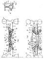
- the wheels 4 of the vehicle which can be steered via tie rods 16 of a rack and pinion steering system, are each pivotably articulated via a lower triangular wishbone 3 to an auxiliary frame, which in turn is detachably screwed to the vehicle body 2, which is only indicated.
- Other necessary wheel guide members be it an upper wishbone or a wheel-guiding suspension strut, and the wheel carrier (steering knuckle) itself are not shown because of the better overview.
- the auxiliary frame and the rack-and-pinion steering or the housing 5 of the rack-and-pinion steering are formed into an integrated, one-piece structural unit 1 made of light metal casting, preferably made of die-cast aluminum or magnesium.
- the light metal cast housing is provided with rib-like, web-like and / or belt-like stiffeners 10 - 13 cast on along its circumference and its length, and with lateral console-like sprues 7 to 9 provided, in the lateral console-like sprues on the one hand bearings 22 for releasably attaching this unit to the vehicle body 2 and on the other hand bearings 20, 21 are provided for pivotably articulating the control arm 3 on the unit;
- the one bearing 20 is designed in a known manner so that it serves both for fastening the assembly to the vehicle body 2 and for the articulation of the control arm 3.
- the housing part 5 which receives the rack 23 and is oriented transversely to the longitudinal direction of the vehicle and which represents the actual rack-and-pinion steering housing and in the usual way has an essentially circular cross-section
- two in plan view approximately Y-shaped obliquely outwards Diverging console-like sprues 7, 8 are formed with bearings 20, 21 arranged at their ends, which primarily serve to pivot the control arm 3 and, in the exemplary embodiment, lie approximately in the same horizontal plane, but this depends in individual cases on the desired kinematics of the wheel guide.
- one of the two bearings, namely bearing 20, also serves at the same time for fastening the cast assembly to the vehicle body 2.
- a further lateral bracket-like sprue 9 is provided above the level that is fictitiously defined by the first two bracket-like sprues 7, 8. At its end, this carries a bearing 22, which is used for releasably fastening the structural unit to the vehicle body 2.
- a T-beam-shaped stiffening 10 extending longitudinally above the housing part 5 receiving the rack 23 is approximately horizontal top flange 11 and approximately vertical Web 12 (Fig. 3) is provided, which opens into the laterally spread console-like sprues 7, 8 and whose vertical web 12 runs approximately symmetrically into the circular cross-section of the housing part 5, at least in the central region.
- On both sides of the stiffening 10 there are alternately oppositely inclined transverse ribs 13 which each extend from the upper chord 11 to the lower region of the housing part 5, in the exemplary embodiment shown up to a corresponding lower chord 17.
- stiffeners e.g. B. U-shaped stiffeners or the like can be used analogously.
- the stiffening 10 - seen in the longitudinal direction of the vehicle - is arched like a bridge, d. H. so that it runs from a central arch apex to the laterally spread console-like sprues 7, 8 sloping downwards and ends there in the console-like sprues 7, 8.
- This bridge-like curvature is advantageous if on the assembly 1 also aggregate parts, for. B. a differential 18 must be supported, and it also facilitates, for. B. to pass the pipe 14 of an exhaust system or the shift linkage 15 of a change gear under the unit 1.
Landscapes
- Engineering & Computer Science (AREA)
- Mechanical Engineering (AREA)
- Chemical & Material Sciences (AREA)
- Combustion & Propulsion (AREA)
- Transportation (AREA)
- Body Structure For Vehicles (AREA)
Abstract
Claims (5)
- Module (1) pouvant être fixé de façon amovible sur la carrosserie (2) d'un véhicule, réunissant les fonctions d'un cadre auxiliaire (faux-châssis) permettant, entre autres choses, l'articulation oscillante de bras de suspension (3) de roues - bras triangulaires de préférence - et d'un carter de direction à crémaillère présentant des renforts supérieurs et/ou inférieurs en forme de ceintures s'étendant le long du carter,
caractérisé en ce que le module (1) est réalisé sous forme d'un module monobloc (1) en métal léger moulé, en ce qu'aux deux extrémités d'une partie (5) de carter, qui reçoit la crémaillère (23), ayant une section transversale essentiellement annulaire circulaire, sont prévus deux appendices (7, 8) en forme de consoles bifurquant obliquement vers l'extérieur, approximativement en forme d'un Y, vu de dessus, comprenant des paliers (20, 21) situés à leurs extrémités, permettant la fixation du module (1) sur la carrosserie (2) du véhicule et/ou permettant l'articulation oscillante d'un bras de suspension (3) de roue, et en ce que d'autres renforts (10, 12, 13) en forme de nervures et d'arêtes, moulés sur la pièce, sont prévus à côté des renforts supérieurs et/ou inférieurs (11, 17) en forme de ceinture, s'étendant longitudinalement le long de la périphérie de la partie (5) de carter. - Module selon la revendication 1, caractérisé par un appendice latéral supplémentaire (9) en forme de console respectivement situé au-dessus d'un plan fictif passant par les deux autres appendices (7, 8) en forme de consoles, et présentant un palier (22) permettant sa fixation sur la carrosserie (2) du véhicule.
- Module selon la revendication 1 ou 2, caractérisé par un renfort (10) en forme de poutre à section en T, en U ou en double T, qui s'étend le long de la partie (5) de carter recevant la crémaillère (23), et qui se termine dans les appendices (7, 8) en forme de consoles, s'écartant latéralement.
- Module selon la revendication 3, caractérisé par des nervures transversales (13) de préférence disposées des deux côtés du renfort (10), inclinées en sens opposés alternativement.
- Module selon la revendication 3 ou 4, caractérisé en ce qu'au niveau de la partie (5) de carter recevant la crémaillère (23), le renfort (10) - vu dans le sens longitudinal du véhicule - s'étend depuis un point apical central d'arc, selon une courbe légèrement descendante, jusqu'aux appendices (7, 8) en forme de consoles s'écartant latéralement, et se termine dans ces appendices (7, 8) en forme de consoles.
Applications Claiming Priority (2)
| Application Number | Priority Date | Filing Date | Title |
|---|---|---|---|
| DE3837679 | 1988-11-05 | ||
| DE3837679 | 1988-11-05 |
Publications (2)
| Publication Number | Publication Date |
|---|---|
| EP0441818A1 EP0441818A1 (fr) | 1991-08-21 |
| EP0441818B1 true EP0441818B1 (fr) | 1993-08-11 |
Family
ID=6366621
Family Applications (1)
| Application Number | Title | Priority Date | Filing Date |
|---|---|---|---|
| EP89911991A Expired - Lifetime EP0441818B1 (fr) | 1988-11-05 | 1989-10-20 | un module fixé de manière amovible à la structure d'un véhicule |
Country Status (3)
| Country | Link |
|---|---|
| EP (1) | EP0441818B1 (fr) |
| DE (1) | DE58905292D1 (fr) |
| WO (1) | WO1990005083A1 (fr) |
Cited By (3)
| Publication number | Priority date | Publication date | Assignee | Title |
|---|---|---|---|---|
| EP1510443A1 (fr) * | 2003-08-25 | 2005-03-02 | Peugeot Citroen Automobiles S.A. | Vèhicule automobile à crèmaillère de direction intègrèe dans la traverse avant |
| DE102006048946A1 (de) * | 2006-10-17 | 2008-04-24 | Volkswagen Ag | Hilfsrahmenanordnung |
| DE102017112049A1 (de) * | 2017-06-01 | 2018-12-06 | Dr. Ing. H.C. F. Porsche Aktiengesellschaft | Fahrschemel für eine Hinterachse eines Kraftfahrzeugs |
Families Citing this family (24)
| Publication number | Priority date | Publication date | Assignee | Title |
|---|---|---|---|---|
| DE58901705D1 (de) * | 1988-03-12 | 1992-07-23 | Zahnradfabrik Friedrichshafen | Lenkbare radachse fuer ein kraftfahrzeug. |
| IT1252202B (it) * | 1991-12-12 | 1995-06-05 | Giuseppe Baggioli | Attuatore idraulico, particolarmente per l'attuazione di servocomandi e simili. |
| FR2710583B1 (fr) * | 1993-09-29 | 1995-12-22 | Peugeot | Train avant pour véhicule automobile. |
| SE508519C2 (sv) * | 1994-06-28 | 1998-10-12 | Volvo Ab | Hjulupphängning för ett par drivna fordonshjul |
| EP0764571B1 (fr) * | 1995-09-20 | 2001-01-17 | Dr.Ing.h.c. F. Porsche Aktiengesellschaft | Traverse d'essieu avant d'un véhicule automobile |
| ES2140014T3 (es) * | 1995-12-11 | 2000-02-16 | Volkswagen Ag | Bastidor auxiliar con una carcasa de fundicion de metal ligero de una direccion de cremallera. |
| DE19703504B4 (de) * | 1996-02-10 | 2006-06-14 | Volkswagen Ag | Hilfsrahmen für ein Kraftfahrzeug |
| DE19608414A1 (de) * | 1996-03-05 | 1997-09-11 | Opel Adam Ag | Fahrschemel für eine gelenkte Achse eines Kraftfahrzeuges |
| DE59708237D1 (de) * | 1996-06-21 | 2002-10-24 | Volkswagen Ag | Hilfsrahmen für ein Kraftfahrzeug |
| DE19701367A1 (de) * | 1997-01-16 | 1998-07-23 | Volkswagen Ag | Motorraumanordnung eines Kraftfahrzeugs |
| DE19730404B4 (de) * | 1997-07-16 | 2005-04-21 | Daimlerchrysler Ag | Hilfsrahmen für Kraftfahrzeuge |
| JP4632222B2 (ja) | 2000-08-24 | 2011-02-16 | 現代自動車株式会社 | ステアリングギヤフレーム |
| GB0107629D0 (en) * | 2001-03-27 | 2001-05-16 | Ricardo Consulting Eng | Motor vehicles |
| FR2866305B1 (fr) * | 2004-02-13 | 2006-05-19 | Peugeot Citroen Automobiles Sa | Berceau modulable pour un vehicule automobile et vehicule automobile comportant un tel berceau |
| WO2007031059A2 (fr) * | 2005-09-13 | 2007-03-22 | Ksm Castings Gmbh | Chassis secondaire destine en particulier a des vehicules automobiles |
| DE502006008675D1 (de) | 2005-09-13 | 2011-02-17 | Ksm Castings Gmbh | Vorderachsträger, insbesondere für kraftfahrzeuge |
| DE102006010130B4 (de) * | 2006-03-06 | 2008-02-21 | KSM Castings GmbH Kloth-Senking Metallgießerei | Hilfsrahmen, insbesondere für Kraftfahrzeuge |
| DE102006010135B4 (de) * | 2006-03-06 | 2010-01-28 | KSM Castings GmbH Kloth-Senking Metallgießerei | Vorderachsträger, insbesondere für Kraftfahrzeuge |
| JP5364718B2 (ja) | 2007-11-08 | 2013-12-11 | カーエスエム キャスティングス グループ ゲーエムベーハー | 自動車用フロントアクスルキャリア |
| DE102008041501A1 (de) | 2008-08-25 | 2010-03-04 | Zf Lenksysteme Gmbh | Vorderbau für ein Fahrzeug |
| DE102009021270A1 (de) * | 2009-05-14 | 2010-11-18 | Volkswagen Ag | Vorderachsanordnung für ein Kraftfahrzeug |
| DE102010025537A1 (de) | 2009-07-06 | 2011-05-05 | Ksm Castings Gmbh | Achsträger, insbesondere Vorderachsträger für Kraftfahrzeuge |
| DE102010030737A1 (de) * | 2010-06-30 | 2012-01-05 | Zf Lenksysteme Gmbh | Lenkgehäuse für eine Lenkeinrichtung in einem Fahrzeug |
| DE102011115387A1 (de) | 2010-11-02 | 2012-05-03 | Ksm Castings Gmbh | Achsträger, insbesondere Vorderachsträger für Kraftfahrzeuge |
Family Cites Families (4)
| Publication number | Priority date | Publication date | Assignee | Title |
|---|---|---|---|---|
| GB1400024A (en) * | 1972-10-02 | 1975-07-16 | Chrysler Uk | Improvements in or relating to front suspension assemblies for motor vehicles |
| GB1470015A (en) * | 1974-12-24 | 1977-04-14 | Chrysler Uk | Engine mountings |
| FR2507988B1 (fr) * | 1981-06-17 | 1986-08-14 | Peugeot | Agencement d'un carter de cremaillere de direction et d'un support de pedales sur un vehicule automobile |
| GB2148807A (en) * | 1983-11-02 | 1985-06-05 | Bl Tech Ltd | Front sub-frame structure for a road vehicle |
-
1989
- 1989-10-20 EP EP89911991A patent/EP0441818B1/fr not_active Expired - Lifetime
- 1989-10-20 WO PCT/EP1989/001255 patent/WO1990005083A1/fr not_active Ceased
- 1989-10-20 DE DE8989911991T patent/DE58905292D1/de not_active Expired - Fee Related
Cited By (4)
| Publication number | Priority date | Publication date | Assignee | Title |
|---|---|---|---|---|
| EP1510443A1 (fr) * | 2003-08-25 | 2005-03-02 | Peugeot Citroen Automobiles S.A. | Vèhicule automobile à crèmaillère de direction intègrèe dans la traverse avant |
| FR2859155A1 (fr) * | 2003-08-25 | 2005-03-04 | Peugeot Citroen Automobiles Sa | Vehicule automobile a cremaillere de direction integree dans la traverse avant |
| DE102006048946A1 (de) * | 2006-10-17 | 2008-04-24 | Volkswagen Ag | Hilfsrahmenanordnung |
| DE102017112049A1 (de) * | 2017-06-01 | 2018-12-06 | Dr. Ing. H.C. F. Porsche Aktiengesellschaft | Fahrschemel für eine Hinterachse eines Kraftfahrzeugs |
Also Published As
| Publication number | Publication date |
|---|---|
| EP0441818A1 (fr) | 1991-08-21 |
| DE58905292D1 (de) | 1993-09-16 |
| WO1990005083A1 (fr) | 1990-05-17 |
Similar Documents
| Publication | Publication Date | Title |
|---|---|---|
| EP0441818B1 (fr) | un module fixé de manière amovible à la structure d'un véhicule | |
| DE3905650C1 (fr) | ||
| DE102006062889B4 (de) | Hilfsrahmen, insbesondere für Kraftfahrzeuge | |
| DE102006062840B4 (de) | Vorderachsträger, insbesondere für Kraftfahrzeuge | |
| EP1925534B1 (fr) | Support pour une jambe de suspension d'un véhicule automobile | |
| EP2547574B1 (fr) | Élément avant d'un véhicule | |
| EP1273502B1 (fr) | Carrosserie de véhicule automobile | |
| DE4200482C2 (de) | Tragestruktur für eine Hinterrad-Aufhängung eines Fahrzeuges | |
| DE3722696C2 (fr) | ||
| DE102006031883A1 (de) | Fahrzeugaufhängungssystem mit Radträger und an Spurstange befestigtem Längslenker | |
| EP1059220A2 (fr) | Structure de carrosserie autoporteuse d'un véhicule automobile | |
| DE19532531A1 (de) | Fahrzeugaufbau | |
| DE112012003879B4 (de) | Struktur für eine untere Fahrzeugkarosserie von einem Fahrzeugvorderteil | |
| EP0779204B1 (fr) | Châssis auxiliaire comprenant le boítier en fonte d'alliage léger d'une direction à crémaillère | |
| EP0816139B1 (fr) | Châssis auxiliaire pour véhicule automobile | |
| DE69012680T2 (de) | Fahrzeugaufhängungs-Befestigungseinheit. | |
| WO2020147963A1 (fr) | Support d'essieu pour véhicule à moteur et sa fabrication | |
| EP0678405B1 (fr) | Partie avant d'autobus comprenant un élément porteur pour suspensions élastiques | |
| DE10104040A1 (de) | Personenkraftwagen mit Einzelradaufhängung und einem Fahrschemel | |
| DE3114415C2 (de) | Aufbauendwand für Personenkraftwagen | |
| DE102007047402B3 (de) | Achslagerung für eine Kraftwagenhinterachse | |
| EP0097622B1 (fr) | Véhicule monotrace avec carrosserie | |
| EP1081024B1 (fr) | Structure avant de véhicule dans la région de l'auvent | |
| DE102009039807A1 (de) | Frontstruktur eines Kraftfahrzeugs | |
| DE102006010130B4 (de) | Hilfsrahmen, insbesondere für Kraftfahrzeuge |
Legal Events
| Date | Code | Title | Description |
|---|---|---|---|
| PUAI | Public reference made under article 153(3) epc to a published international application that has entered the european phase |
Free format text: ORIGINAL CODE: 0009012 |
|
| 17P | Request for examination filed |
Effective date: 19910402 |
|
| AK | Designated contracting states |
Kind code of ref document: A1 Designated state(s): DE FR GB IT |
|
| 17Q | First examination report despatched |
Effective date: 19920821 |
|
| GRAA | (expected) grant |
Free format text: ORIGINAL CODE: 0009210 |
|
| AK | Designated contracting states |
Kind code of ref document: B1 Designated state(s): DE FR GB IT |
|
| REF | Corresponds to: |
Ref document number: 58905292 Country of ref document: DE Date of ref document: 19930916 |
|
| ET | Fr: translation filed | ||
| ITF | It: translation for a ep patent filed | ||
| GBT | Gb: translation of ep patent filed (gb section 77(6)(a)/1977) |
Effective date: 19931118 |
|
| PLBE | No opposition filed within time limit |
Free format text: ORIGINAL CODE: 0009261 |
|
| STAA | Information on the status of an ep patent application or granted ep patent |
Free format text: STATUS: NO OPPOSITION FILED WITHIN TIME LIMIT |
|
| 26N | No opposition filed | ||
| REG | Reference to a national code |
Ref country code: GB Ref legal event code: IF02 |
|
| PGFP | Annual fee paid to national office [announced via postgrant information from national office to epo] |
Ref country code: GB Payment date: 20030930 Year of fee payment: 15 |
|
| PGFP | Annual fee paid to national office [announced via postgrant information from national office to epo] |
Ref country code: FR Payment date: 20031024 Year of fee payment: 15 |
|
| PG25 | Lapsed in a contracting state [announced via postgrant information from national office to epo] |
Ref country code: GB Free format text: LAPSE BECAUSE OF NON-PAYMENT OF DUE FEES Effective date: 20041020 |
|
| GBPC | Gb: european patent ceased through non-payment of renewal fee |
Effective date: 20041020 |
|
| PG25 | Lapsed in a contracting state [announced via postgrant information from national office to epo] |
Ref country code: FR Free format text: LAPSE BECAUSE OF NON-PAYMENT OF DUE FEES Effective date: 20050630 |
|
| REG | Reference to a national code |
Ref country code: FR Ref legal event code: ST |
|
| PG25 | Lapsed in a contracting state [announced via postgrant information from national office to epo] |
Ref country code: IT Free format text: LAPSE BECAUSE OF NON-PAYMENT OF DUE FEES;WARNING: LAPSES OF ITALIAN PATENTS WITH EFFECTIVE DATE BEFORE 2007 MAY HAVE OCCURRED AT ANY TIME BEFORE 2007. THE CORRECT EFFECTIVE DATE MAY BE DIFFERENT FROM THE ONE RECORDED. Effective date: 20051020 |
|
| PGFP | Annual fee paid to national office [announced via postgrant information from national office to epo] |
Ref country code: DE Payment date: 20051031 Year of fee payment: 17 |
|
| PG25 | Lapsed in a contracting state [announced via postgrant information from national office to epo] |
Ref country code: DE Free format text: LAPSE BECAUSE OF NON-PAYMENT OF DUE FEES Effective date: 20070501 |