EP0441829B1 - Vorrichtung zum spülen und reinigen des magen-darm-traktes von menschen und tieren - Google Patents
Vorrichtung zum spülen und reinigen des magen-darm-traktes von menschen und tieren Download PDFInfo
- Publication number
- EP0441829B1 EP0441829B1 EP89912150A EP89912150A EP0441829B1 EP 0441829 B1 EP0441829 B1 EP 0441829B1 EP 89912150 A EP89912150 A EP 89912150A EP 89912150 A EP89912150 A EP 89912150A EP 0441829 B1 EP0441829 B1 EP 0441829B1
- Authority
- EP
- European Patent Office
- Prior art keywords
- nozzle
- water
- conduit
- valve
- drain
- Prior art date
- Legal status (The legal status is an assumption and is not a legal conclusion. Google has not performed a legal analysis and makes no representation as to the accuracy of the status listed.)
- Expired - Lifetime
Links
- 241001465754 Metazoa Species 0.000 title claims abstract description 4
- 230000002496 gastric effect Effects 0.000 title claims abstract description 4
- 241000282414 Homo sapiens Species 0.000 title abstract 2
- 238000004140 cleaning Methods 0.000 title abstract 2
- XLYOFNOQVPJJNP-UHFFFAOYSA-N water Substances O XLYOFNOQVPJJNP-UHFFFAOYSA-N 0.000 claims abstract description 76
- 239000000463 material Substances 0.000 claims abstract description 5
- 230000005484 gravity Effects 0.000 claims abstract description 4
- 238000007599 discharging Methods 0.000 claims abstract description 3
- 230000002262 irrigation Effects 0.000 claims description 3
- 238000003973 irrigation Methods 0.000 claims description 3
- 238000011144 upstream manufacturing Methods 0.000 claims description 2
- 230000008878 coupling Effects 0.000 claims 1
- 238000010168 coupling process Methods 0.000 claims 1
- 238000005859 coupling reaction Methods 0.000 claims 1
- 241000792859 Enema Species 0.000 description 11
- 239000007920 enema Substances 0.000 description 11
- 229940095399 enema Drugs 0.000 description 11
- 210000002445 nipple Anatomy 0.000 description 9
- 238000000034 method Methods 0.000 description 7
- 230000000968 intestinal effect Effects 0.000 description 6
- 210000003205 muscle Anatomy 0.000 description 5
- 210000000936 intestine Anatomy 0.000 description 4
- 210000000664 rectum Anatomy 0.000 description 3
- 238000004659 sterilization and disinfection Methods 0.000 description 3
- 241000048246 Gallicrex cinerea Species 0.000 description 2
- 230000000694 effects Effects 0.000 description 2
- 210000003736 gastrointestinal content Anatomy 0.000 description 2
- 239000007788 liquid Substances 0.000 description 2
- 230000007704 transition Effects 0.000 description 2
- 241000894006 Bacteria Species 0.000 description 1
- 238000013459 approach Methods 0.000 description 1
- 239000003795 chemical substances by application Substances 0.000 description 1
- 230000008602 contraction Effects 0.000 description 1
- 230000000593 degrading effect Effects 0.000 description 1
- 238000010586 diagram Methods 0.000 description 1
- 238000011010 flushing procedure Methods 0.000 description 1
- 238000003780 insertion Methods 0.000 description 1
- 230000037431 insertion Effects 0.000 description 1
- 239000000203 mixture Substances 0.000 description 1
- 229920003023 plastic Polymers 0.000 description 1
- 238000007789 sealing Methods 0.000 description 1
- 210000002784 stomach Anatomy 0.000 description 1
Images

Classifications
-
- A—HUMAN NECESSITIES
- A61—MEDICAL OR VETERINARY SCIENCE; HYGIENE
- A61M—DEVICES FOR INTRODUCING MEDIA INTO, OR ONTO, THE BODY; DEVICES FOR TRANSDUCING BODY MEDIA OR FOR TAKING MEDIA FROM THE BODY; DEVICES FOR PRODUCING OR ENDING SLEEP OR STUPOR
- A61M3/00—Medical syringes, e.g. enemata; Irrigators
- A61M3/02—Enemata; Irrigators
- A61M3/0233—Enemata; Irrigators characterised by liquid supply means, e.g. from pressurised reservoirs
- A61M3/0241—Enemata; Irrigators characterised by liquid supply means, e.g. from pressurised reservoirs the liquid being supplied by gravity
-
- A—HUMAN NECESSITIES
- A61—MEDICAL OR VETERINARY SCIENCE; HYGIENE
- A61M—DEVICES FOR INTRODUCING MEDIA INTO, OR ONTO, THE BODY; DEVICES FOR TRANSDUCING BODY MEDIA OR FOR TAKING MEDIA FROM THE BODY; DEVICES FOR PRODUCING OR ENDING SLEEP OR STUPOR
- A61M1/00—Suction or pumping devices for medical purposes; Devices for carrying-off, for treatment of, or for carrying-over, body-liquids; Drainage systems
- A61M1/36—Other treatment of blood in a by-pass of the natural circulatory system, e.g. temperature adaptation, irradiation ; Extra-corporeal blood circuits
- A61M1/3621—Extra-corporeal blood circuits
- A61M1/3643—Priming, rinsing before or after use
-
- A—HUMAN NECESSITIES
- A61—MEDICAL OR VETERINARY SCIENCE; HYGIENE
- A61M—DEVICES FOR INTRODUCING MEDIA INTO, OR ONTO, THE BODY; DEVICES FOR TRANSDUCING BODY MEDIA OR FOR TAKING MEDIA FROM THE BODY; DEVICES FOR PRODUCING OR ENDING SLEEP OR STUPOR
- A61M2205/00—General characteristics of the apparatus
- A61M2205/36—General characteristics of the apparatus related to heating or cooling
- A61M2205/3626—General characteristics of the apparatus related to heating or cooling by controlled mixing of fluids at different temperatures
-
- A—HUMAN NECESSITIES
- A61—MEDICAL OR VETERINARY SCIENCE; HYGIENE
- A61M—DEVICES FOR INTRODUCING MEDIA INTO, OR ONTO, THE BODY; DEVICES FOR TRANSDUCING BODY MEDIA OR FOR TAKING MEDIA FROM THE BODY; DEVICES FOR PRODUCING OR ENDING SLEEP OR STUPOR
- A61M3/00—Medical syringes, e.g. enemata; Irrigators
- A61M3/02—Enemata; Irrigators
- A61M3/0233—Enemata; Irrigators characterised by liquid supply means, e.g. from pressurised reservoirs
- A61M3/0245—Containers therefor, e.g. with heating means or with storage means for cannula
Definitions
- the invention relates to an apparatus for gastro-intestinal irrigation and cleansing of humans and animals comprising a water container having cold and hot water connections for the supply of temperated water to the container, and a nozzle which can be connected by hoses over valve controlled conduits to the water container for supply of water to the nozzle from the water container by gravity and to a drain for discharging flowing material from the nozzle to the drain, the cold water connection being connected via a shut-off valve to the conduit from the water container to the nozzle and via a shut-off valve to the drain, the nozzle hoses being transparent and detachably connected to the valve controlled conduits from the water container and to the drain, respectively, whereby in a conduit connecting the cold water connection to the drain there is provided separate adjustable choke means.
- the apparatus is primarily intended for the enema process but can be used also for irrigating and cleansing the stomach.
- the advantage provided by such apparatus is that the treatment takes place in a closed system, and as a consequence thereof the treatment will be considerably less trying physically as well as mentally for the person treated than the conventional enema and, moreover, that the treatment can be carried out faster and considerably more hygienically than the conventional enema with the patient lying the whole time on a couch.
- the purpose of the present invention is to improve further the apparatus so that the function thereof can be adapted to the condition of the person to be treated and the very strict hygienic requirements applied nowadays can be satisfied, implying that medical apparatus should be kept free of bacteria.
- the apparatus of the kind referred to above according to the invention has obtained the characterizing features of claim l, whereby the drainage through the nozzle can be positively carried out by suction the effect thereof being adjusted to the condition of the patient, and the apparatus can be cleaned and sterilized in a very simple and effective manner.
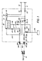
- the functional elements shown inside the rectangle indicated by dot-and-dash lines in FIG l are located inside a housing l0, FIG 2, which preferably is made of stainless sheet and is shaped such that it can be located in a corner of a room so as to require the smallest possible space.
- the apparatus is connected to a conduit ll for cold water and a conduit l2 for hot water via check valves l3 and l4, respectively, and a mixer l5 with control means l6 is connected to said conduits.
- the outlet of the mixer is connected via a shut-off cock l7 to a water container l8 located in the upper portion of the apparatus.
- the water container has an outlet conduit l9 connected to a bottom thereof, to which a conduit 20 is connected, said conduit being connected via a shut-off valve 2l to a nipple 22 available at the outside of the housing l0.
- An overflow 23 for the water container is connected to the conduit l9 which opens via a shut-off valve 24 in a drainage system 25.
- a conduit 26 having a shut-off valve 27 is connected to the conduit 20, and said conduit 26 opens in the water container at a location above the uppermost water level in the water container defined by the overflow 23.
- a conduit 28 having a shut-off valve 29 is connected to the conduit 20, and said conduit 29 extends from the cold water conduit 3l which is also connected by a conduit 30 having an adjustable choke member 3l the control means of which is indicated at 32, and a shut-off valve 33, to an injector (water type suction device) 34 having an outlet to the drainage system 25.
- the suction conduit 35 of the injector is connected via a shut-off valve 36 and a check valve 37 to a nipple 38 which is available at the outside of the housing l0 and is located adjacent the nipple 22.
- Transparent hoses 39 and 40 are detachably connected to the nipples 22 and 38, respectively, said hoses extending to a rectal nozzle 4l.
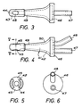
- the rectal nozzle 4l is circular in the cross sections thereof and is anatomatically shaped in the longitudinal direction in order that the insertion into the rectum will be facilitated and optimum sealing against the intestinal wall and the rectal muscle and - when patients having undergone stomi-operation are treated - against the skin and the intestinal wall at the intestinal outlet will be obtained.
- the nozzle has a through internal passage 42 which in the forward portion 43 opens into a centrally positioned supply opening 44 and in the sides of said portion opens into two (or more) discharge openings 45.
- two connection tubes 47 and 48 are provided communicating with the passage 42, and the two hoses 39 and 40 are connected each to one of these connection tubes.
- the forward portion of the rectal nozzle is shaped so as to simplify and facilitate the application of the nozzle at and during the treatment.
- the forward, outside portion of the nozzle is smoothly curved so as to prevent damage of the intestine and the rectal muscle and to lower the level of pain when the nozzle is being inserted into the rectum and prevent reflectory contraction of the rectal muscle.
- the forward portion 43 of the nozzle has a larger diameter than the central portion 49 and, therefore, the openings 45 can be made relatively large so as to pass larger fractions of the intestinal content without the risk of stoppage.
- the forward, larger portion has passed the rectal muscle which then encircles the following narrower portion 49, this muscle will be less strained but prevents simultaneously the nozzle from spontaneously slipping out of the intestine.
- the length of the thicker portion 43 provides an indication of how far the nozzle should be inserted into the intestinal opening.
- the rear portion 46 of the nozzle has a substantially larger diameter than the central portion 49 and the forward portion 43. From the central portion the diameter is increased by a smooth transition 50 to the largest diameter which approaches the double diameter of the central portion. The function of this enlargement is that the portion at the smooth transition from a small to a large diameter when said enlarged portion is pressed against the rectal opening will form a tight connection at said opening. This is of particular importance in treating elderly patients whose rectal functions often are weakened.
- the rectal nozzle is made of a transparent plastics material and suitably is a one-way product.
- the two fixedly attached connection tubes 47 and 48 are formed as nipples for hose connection.
- Necessary control means for the cock and the shut-off valves as well as necessary check means are provided on the outside surface of the housing l0.
- an operating handle l27 for the air valve 27 an operating handle l33 for the valve 33 used for applying a negative pressure in the conduit 35, a knob l32 connected to the adjustment means 32 for adjusting the negative pressure in the conduit 35, an operating handle l2l for the valve 2l which can be marked "To patient”, an operating handle l36 for the valve 36, which can be marked “From patient”, an operating handle ll7 for the water cock l7, a knob ll6 for adjusting the control means l6 for the mixer for setting a suitable temperature of the water supplied from the mixer, an operating handle l24 for the valve 24 for emptying the water container, and an operating handle l29 for the valve 29.
- a level meter 5l for indicating the water level in the water container and a digital thermometer 52 for indicating the temperature of the water in the water
- the negative pressure to be maintained in the conduit 35 initially is adjusted.
- the hose 40 (detached from the nozzle) is immersed into a bucket with water valves 33 and 36 then being opened.
- the injector 34 By means of the injector 34 a negative pressure is developed in the hose 40 a water column being sucked up into said hose.
- the water column can be seen through the transparent hose, and at the knob l32 the water flow through the injector is adjusted such that the desired negative pressure will be obtained; the distance from the water column to the nipple 38 can be used as a measure of the negative pressure. For example it may be prescribed for the use of the apparatus that this distance in the normal case should be about l0 cm.
- the water container l8 is filled with body temperated water by opening the cock l7 with the knob ll6 adjusted to the suitable temperature which is read on the thermometer 52 the water container initially being flushed by the valve 24 being maintained in the open position.
- the valve 27 in the air conduit 26 is opened and then the valve 2l is opened, water flowing by gravity from the water container through the conduits l9 and 20, the hose 39 and the nozzle 4l into the intestine of the patient.
- the water is airated via the conduit 26 the air being preheated by being taken from the water container l8 above the surface of the body hot water contained therein.
- the air contributes to an expansion of the intestine so that walls and intestinal cavities will be available for the liquid, which means that the cleansing effect will be optimated and that the treatment time as a consequence thereof can be reduced in relation to that required at conventional enema.
- nipples 22 and 38 are short circuited by connecting a short hose connection indicated by dot-and-dash lines at 53 between the nipples.
- the valve 36 is opened as is the valve 29 cold water flushing through the conduits 20 and 35 via the hose 53 to the drainage system 25.
- the valves 2l and 33 are open for evacuating the conduits and the hose. Then, all valves are closed, and the apparatus is ready to be used again.
- the water container l8 With the hose 53 connected to the nipples 22 and 38 and with the valve 2l open the water container l8 is filled with water by opening the cock l7 and admixing a disinfection agent into the water in the container. When the mixture has been left for an hour or so the valves 24 and 36 are opened, the conduits l9, 20 and 35 being flushed with disinfection liquid. The procedure is repeated some times with water only from the water container l8 the cleaning program described above then being run through in order to prepare the apparatus for enema.
- the check valve 37 guarantees that cold water at water tap pressure cannot be supplied to the patient via the rectal nozzle 4l if the injector 34 should fail or stoppage should arise in the drainage system 25.
- the operating handle l29 of the valve 29 should be located so that it is separated from other control handles regularly used in treating a patient by means of the apparatus, as is also disclosed in FIG 2, and the access thereof should be more difficult than in case of other operating handles and, preferably, the handle should be marked with a particular colour, for example painted in red colour.
- the apparatus of the invention allows enema in a closed system in a simple and effective manner the apparatus being operated by simple manipulation, and that the apparatus in a simple manner can be adjusted for use and can be cleaned and disinfected in order to satisfy strict hygienic requirements at the level maintained nowadays in the medical care.
- the cleansing procedure can be effected more rapidly and with a better result than when conventional enema is used.
Landscapes
- Health & Medical Sciences (AREA)
- Engineering & Computer Science (AREA)
- Anesthesiology (AREA)
- Biomedical Technology (AREA)
- Heart & Thoracic Surgery (AREA)
- Hematology (AREA)
- Life Sciences & Earth Sciences (AREA)
- Animal Behavior & Ethology (AREA)
- General Health & Medical Sciences (AREA)
- Public Health (AREA)
- Veterinary Medicine (AREA)
- Infusion, Injection, And Reservoir Apparatuses (AREA)
Claims (5)
- Verfahren zum Spülen und Reinigen des Magen-Darm-Traktes von Menschen und Tieren, die einen Wasserbehälter (18) mit Kalt- und Warmwasserverbindungen (11, 12, 15) zur zufuhr von temperiertem Wasser zum Behälter, und eine Düse (41) umfaßt, die durch Schläuche (39, 40) über ventilgesteuerte Leitungen (20, 35) mit dem Wasserbehälter verbunden werden kann, um Wasser durch die Schwerkraft vom Wasserbehälter zur Düse und zum Ablauf (25) zu leiten, um das aus der Düse strömende Material zum Ablauf abzugeben, wobei die Kaltwasserverbindung (11) durch ein Absperrventil (29) mit der Leitung (20) vom Wasserbehälter (18) zur Düse (41) und durch ein Absperrventil (33) mit dem Ablauf (25) verbunden ist, wobei die Schläuche der Düse transparent und lösbar mit den ventilgesteuerten Leitungen (20, 35) vom Wasserbehälter bzw. zum Ablauf verbunden sind, wodurch in der Leitung (30), die die Kaltwasserverbindung (11) mit dem Ablauf (25) verbindet, eine separat regelbare Drosseleinrichtung (31) geschaffen wird, dadurch gekennzeichnet, daß stromabwarts der Drosseleinrichtung (31) ein Injektor (34) vorgesehen ist, dessen Ansaugeinlaß mit der Leitung (35) von der Düse (41) zum Ablauf (25) verbunden ist, um die Düse durch den Injektor mit dem Ablauf zu verbinden, so daß in der Leitung (35) von der Düse zum Ablauf (25) eine Saugwirkung erzeugt wird, wobei das Regelventil (37) in der Ablaufleitung (35) der Düse vorgesehen ist, um die Strömung durch die Leitung zur Düse (41) zu verhindern, wobei die Schläuche der Düse durch Schlauchverbindungen (22, 38), die außerhalb auf dem Gehäuse (10) zugänglich sind, das den Rest der Vorrichtung umgibt, mit den ventilgesteuerten Leitungen (20, 35) verbunden sind.
- Vorrichtung nach Anspruch 1, worin die Bedienungseinrichtung (129) für das Absperrventil in der Kaltwasserverbindung (11) zur zufuhrleitung (20) der Düse (41) von der Bedienungs- und Regeleinrichtung für die anderen funktionellen Elemente der Vorrichtung getrennt ist, und der zutritt zu dieser vorzugsweise schwieriger als der zu den anderen Elementen ist.
- Vorrichtung nach Anspruch 1 oder 2, worin die Kaltwasserverbindung (11) zur zufuhrleitung (20) der Düse (41) stromabwärts des Absperrventils (21) für die Verbindung zwischen dem Wasserbehälter (18) und der Düse angeordnet ist.
- Vorrichtung nach einem der Ansprüche 1 bis 3, worin die ventilgesteuerte Leitung (26) zur zufuhr von Gas, vorzugsweise Luft, zum Wasserstrom durch die Verbindung zwischen dem Wasserbehälter (18) und der Düse (41) mit der Verbindung stromaufwärts des Absperrventils (21) verbunden ist.
- Vorrichtung nach Anspruch 4, worin die Leitung (26) in den Wasserbehälter (18) oberhalb des maximalen Wasserniveaus in diesem Behälter mündet, das durch den Überlauf (23) definiert wird.
Applications Claiming Priority (4)
| Application Number | Priority Date | Filing Date | Title |
|---|---|---|---|
| SE8804015 | 1988-11-07 | ||
| SE8804016 | 1988-11-07 | ||
| SE8804016 | 1988-11-07 | ||
| SE8804015 | 1988-11-07 |
Publications (2)
| Publication Number | Publication Date |
|---|---|
| EP0441829A1 EP0441829A1 (de) | 1991-08-21 |
| EP0441829B1 true EP0441829B1 (de) | 1992-09-23 |
Family
ID=26660344
Family Applications (1)
| Application Number | Title | Priority Date | Filing Date |
|---|---|---|---|
| EP89912150A Expired - Lifetime EP0441829B1 (de) | 1988-11-07 | 1989-11-07 | Vorrichtung zum spülen und reinigen des magen-darm-traktes von menschen und tieren |
Country Status (3)
| Country | Link |
|---|---|
| EP (1) | EP0441829B1 (de) |
| AU (1) | AU4500589A (de) |
| WO (1) | WO1990004983A1 (de) |
Cited By (1)
| Publication number | Priority date | Publication date | Assignee | Title |
|---|---|---|---|---|
| CN108525046A (zh) * | 2018-04-18 | 2018-09-14 | 孔慧君 | 一种儿科医生用儿科负压洗胃装置 |
Families Citing this family (3)
| Publication number | Priority date | Publication date | Assignee | Title |
|---|---|---|---|---|
| SE9102787L (sv) * | 1991-09-25 | 1993-03-26 | Birgitta Bjoerk | Oeronspolningsutrustning |
| WO2008121839A1 (en) | 2007-03-29 | 2008-10-09 | Jbs Swift & Company | Method and system for washing intestines |
| WO2020200390A1 (en) | 2019-04-05 | 2020-10-08 | Coloplast A/S | An anal irrigation system and related methods for maintaining |
Family Cites Families (6)
| Publication number | Priority date | Publication date | Assignee | Title |
|---|---|---|---|---|
| US1949574A (en) * | 1931-06-06 | 1934-03-06 | Willam F Cremean | Irrigator |
| US1949575A (en) * | 1931-12-17 | 1934-03-06 | William F Cremean | Irrigator |
| US2148541A (en) * | 1935-12-10 | 1939-02-28 | Hugh E Dierker | Colon therapy device and applicator therefor |
| US2157756A (en) * | 1936-04-01 | 1939-05-09 | Walter G Berg | Irrigating apparatus |
| US2313805A (en) * | 1941-11-08 | 1943-03-16 | Boyd B Crawford | Colonic irrigator |
| WO1987001596A1 (en) * | 1985-09-12 | 1987-03-26 | Dotolo, Vincent | Method, colonic speculum and control device for colonic lavage |
-
1989
- 1989-11-07 AU AU45005/89A patent/AU4500589A/en not_active Abandoned
- 1989-11-07 WO PCT/SE1989/000631 patent/WO1990004983A1/en not_active Ceased
- 1989-11-07 EP EP89912150A patent/EP0441829B1/de not_active Expired - Lifetime
Cited By (1)
| Publication number | Priority date | Publication date | Assignee | Title |
|---|---|---|---|---|
| CN108525046A (zh) * | 2018-04-18 | 2018-09-14 | 孔慧君 | 一种儿科医生用儿科负压洗胃装置 |
Also Published As
| Publication number | Publication date |
|---|---|
| EP0441829A1 (de) | 1991-08-21 |
| AU4500589A (en) | 1990-05-28 |
| WO1990004983A1 (en) | 1990-05-17 |
Similar Documents
| Publication | Publication Date | Title |
|---|---|---|
| US2466042A (en) | Internal heat-treatment device | |
| US3288140A (en) | Means for treating surface wounds | |
| US5688239A (en) | Urinary tract treating assembly with prostate flushing | |
| US5030202A (en) | Lavage system | |
| US4874363A (en) | Colon hydrotherapy and evacuator system | |
| US4194506A (en) | Kit for an ostomate | |
| US6090069A (en) | Irrigation and drainage urinary catheter | |
| US3747595A (en) | Jet throat irrigation | |
| US3756237A (en) | Irrigation solution administration system and reservoir therefor | |
| US2331226A (en) | Surgical irrigating equipment | |
| US2957476A (en) | Mouth washing device | |
| KR0157987B1 (ko) | 뇨 실금환자용 개량된 시스템 | |
| US2538215A (en) | Enema apparatus | |
| JP2003520066A (ja) | オストミー洗浄装置 | |
| EP1488821A2 (de) | Drainage- und Infusionskatheter und Kontrolle | |
| US3672370A (en) | Colostomy irrigator | |
| JPS5841553A (ja) | 潅注スリ−ブおよびそのアタツチメント | |
| US7762997B2 (en) | Hygienic and therapeutic vaginal cleansing and hydromassaging device | |
| ATE342743T1 (de) | Anschlussventil für eine magenpumpe | |
| WO1990004983A1 (en) | Apparatus for gastro-intestinal rinsing and cleaning of human beings and animals | |
| US2869547A (en) | Colostomy irrigator | |
| US2832341A (en) | Method of giving peristaltic enemas | |
| US2299431A (en) | Colostomy appliance | |
| US2157614A (en) | Colonic irrigator | |
| US2791218A (en) | Douche nozzle |
Legal Events
| Date | Code | Title | Description |
|---|---|---|---|
| PUAI | Public reference made under article 153(3) epc to a published international application that has entered the european phase |
Free format text: ORIGINAL CODE: 0009012 |
|
| 17P | Request for examination filed |
Effective date: 19910502 |
|
| AK | Designated contracting states |
Kind code of ref document: A1 Designated state(s): BE DE FR GB LU NL SE |
|
| 17Q | First examination report despatched |
Effective date: 19911211 |
|
| GRAA | (expected) grant |
Free format text: ORIGINAL CODE: 0009210 |
|
| AK | Designated contracting states |
Kind code of ref document: B1 Designated state(s): BE DE FR GB LU NL SE |
|
| PG25 | Lapsed in a contracting state [announced via postgrant information from national office to epo] |
Ref country code: NL Effective date: 19920923 |
|
| REF | Corresponds to: |
Ref document number: 68902992 Country of ref document: DE Date of ref document: 19921029 |
|
| ET | Fr: translation filed | ||
| NLV1 | Nl: lapsed or annulled due to failure to fulfill the requirements of art. 29p and 29m of the patents act | ||
| PLBE | No opposition filed within time limit |
Free format text: ORIGINAL CODE: 0009261 |
|
| STAA | Information on the status of an ep patent application or granted ep patent |
Free format text: STATUS: NO OPPOSITION FILED WITHIN TIME LIMIT |
|
| 26N | No opposition filed | ||
| PGFP | Annual fee paid to national office [announced via postgrant information from national office to epo] |
Ref country code: LU Payment date: 19931201 Year of fee payment: 5 |
|
| PGFP | Annual fee paid to national office [announced via postgrant information from national office to epo] |
Ref country code: GB Payment date: 19931207 Year of fee payment: 5 |
|
| PGFP | Annual fee paid to national office [announced via postgrant information from national office to epo] |
Ref country code: FR Payment date: 19931228 Year of fee payment: 5 |
|
| PGFP | Annual fee paid to national office [announced via postgrant information from national office to epo] |
Ref country code: BE Payment date: 19940104 Year of fee payment: 5 |
|
| EPTA | Lu: last paid annual fee | ||
| PGFP | Annual fee paid to national office [announced via postgrant information from national office to epo] |
Ref country code: DE Payment date: 19940128 Year of fee payment: 5 |
|
| PG25 | Lapsed in a contracting state [announced via postgrant information from national office to epo] |
Ref country code: LU Free format text: LAPSE BECAUSE OF NON-PAYMENT OF DUE FEES Effective date: 19941107 Ref country code: GB Effective date: 19941107 |
|
| PG25 | Lapsed in a contracting state [announced via postgrant information from national office to epo] |
Ref country code: BE Effective date: 19941130 |
|
| EAL | Se: european patent in force in sweden |
Ref document number: 89912150.3 |
|
| PGFP | Annual fee paid to national office [announced via postgrant information from national office to epo] |
Ref country code: SE Payment date: 19950420 Year of fee payment: 6 |
|
| BERE | Be: lapsed |
Owner name: MINTHON LENNART Effective date: 19941130 |
|
| GBPC | Gb: european patent ceased through non-payment of renewal fee |
Effective date: 19941107 |
|
| PG25 | Lapsed in a contracting state [announced via postgrant information from national office to epo] |
Ref country code: FR Effective date: 19950731 |
|
| PG25 | Lapsed in a contracting state [announced via postgrant information from national office to epo] |
Ref country code: DE Effective date: 19950801 |
|
| REG | Reference to a national code |
Ref country code: FR Ref legal event code: ST |
|
| PG25 | Lapsed in a contracting state [announced via postgrant information from national office to epo] |
Ref country code: SE Effective date: 19951108 |
|
| EUG | Se: european patent has lapsed |
Ref document number: 89912150.3 |