EP0441887B1 - Verfahren zur behandlung von löchern - Google Patents
Verfahren zur behandlung von löchern Download PDFInfo
- Publication number
- EP0441887B1 EP0441887B1 EP89912994A EP89912994A EP0441887B1 EP 0441887 B1 EP0441887 B1 EP 0441887B1 EP 89912994 A EP89912994 A EP 89912994A EP 89912994 A EP89912994 A EP 89912994A EP 0441887 B1 EP0441887 B1 EP 0441887B1
- Authority
- EP
- European Patent Office
- Prior art keywords
- orifice
- processing
- fluid
- flow resistance
- processing fluid
- Prior art date
- Legal status (The legal status is an assumption and is not a legal conclusion. Google has not performed a legal analysis and makes no representation as to the accuracy of the status listed.)
- Expired - Lifetime
Links
- 238000000034 method Methods 0.000 title claims abstract description 87
- 238000012545 processing Methods 0.000 title claims abstract description 87
- 239000012530 fluid Substances 0.000 claims abstract description 111
- 238000003754 machining Methods 0.000 claims abstract description 63
- 239000000126 substance Substances 0.000 claims abstract description 30
- 239000003792 electrolyte Substances 0.000 claims abstract description 16
- 238000007740 vapor deposition Methods 0.000 claims abstract description 16
- 239000012159 carrier gas Substances 0.000 claims abstract description 7
- 238000009760 electrical discharge machining Methods 0.000 claims description 26
- 230000008569 process Effects 0.000 claims description 22
- 238000009713 electroplating Methods 0.000 claims description 21
- 238000007772 electroless plating Methods 0.000 claims description 18
- 238000006073 displacement reaction Methods 0.000 claims description 9
- 239000008151 electrolyte solution Substances 0.000 claims description 7
- 238000005086 pumping Methods 0.000 claims description 5
- 230000008859 change Effects 0.000 claims description 3
- 229940021013 electrolyte solution Drugs 0.000 claims 1
- 238000007747 plating Methods 0.000 abstract description 35
- 238000000576 coating method Methods 0.000 abstract description 23
- 229910052751 metal Inorganic materials 0.000 description 20
- 239000002184 metal Substances 0.000 description 20
- 239000000463 material Substances 0.000 description 19
- 239000011248 coating agent Substances 0.000 description 17
- 238000001816 cooling Methods 0.000 description 10
- 239000007789 gas Substances 0.000 description 10
- 239000000446 fuel Substances 0.000 description 9
- 238000005553 drilling Methods 0.000 description 7
- 239000010410 layer Substances 0.000 description 7
- 239000007788 liquid Substances 0.000 description 6
- 239000000243 solution Substances 0.000 description 6
- 238000005266 casting Methods 0.000 description 5
- 238000004519 manufacturing process Methods 0.000 description 5
- 230000009467 reduction Effects 0.000 description 5
- 238000000151 deposition Methods 0.000 description 4
- 230000008021 deposition Effects 0.000 description 4
- 239000002245 particle Substances 0.000 description 4
- 230000003746 surface roughness Effects 0.000 description 4
- UFHFLCQGNIYNRP-UHFFFAOYSA-N Hydrogen Chemical compound [H][H] UFHFLCQGNIYNRP-UHFFFAOYSA-N 0.000 description 3
- 239000003082 abrasive agent Substances 0.000 description 3
- 230000009471 action Effects 0.000 description 3
- 230000008901 benefit Effects 0.000 description 3
- 239000003518 caustics Substances 0.000 description 3
- 239000003638 chemical reducing agent Substances 0.000 description 3
- 238000000975 co-precipitation Methods 0.000 description 3
- 230000003247 decreasing effect Effects 0.000 description 3
- 238000013461 design Methods 0.000 description 3
- 150000002500 ions Chemical class 0.000 description 3
- 150000002739 metals Chemical class 0.000 description 3
- 238000004513 sizing Methods 0.000 description 3
- 239000002904 solvent Substances 0.000 description 3
- 238000012360 testing method Methods 0.000 description 3
- XLYOFNOQVPJJNP-UHFFFAOYSA-N water Substances O XLYOFNOQVPJJNP-UHFFFAOYSA-N 0.000 description 3
- IJGRMHOSHXDMSA-UHFFFAOYSA-N Atomic nitrogen Chemical compound N#N IJGRMHOSHXDMSA-UHFFFAOYSA-N 0.000 description 2
- PXHVJJICTQNCMI-UHFFFAOYSA-N Nickel Chemical compound [Ni] PXHVJJICTQNCMI-UHFFFAOYSA-N 0.000 description 2
- KDLHZDBZIXYQEI-UHFFFAOYSA-N Palladium Chemical compound [Pd] KDLHZDBZIXYQEI-UHFFFAOYSA-N 0.000 description 2
- FAPWRFPIFSIZLT-UHFFFAOYSA-M Sodium chloride Chemical compound [Na+].[Cl-] FAPWRFPIFSIZLT-UHFFFAOYSA-M 0.000 description 2
- 239000002253 acid Substances 0.000 description 2
- 239000000956 alloy Substances 0.000 description 2
- 229910045601 alloy Inorganic materials 0.000 description 2
- 238000004364 calculation method Methods 0.000 description 2
- 238000005229 chemical vapour deposition Methods 0.000 description 2
- 239000002131 composite material Substances 0.000 description 2
- 239000000499 gel Substances 0.000 description 2
- 238000010438 heat treatment Methods 0.000 description 2
- 229910052739 hydrogen Inorganic materials 0.000 description 2
- 239000001257 hydrogen Substances 0.000 description 2
- 239000010687 lubricating oil Substances 0.000 description 2
- 238000005259 measurement Methods 0.000 description 2
- 150000001247 metal acetylides Chemical class 0.000 description 2
- VNWKTOKETHGBQD-UHFFFAOYSA-N methane Chemical compound C VNWKTOKETHGBQD-UHFFFAOYSA-N 0.000 description 2
- 239000000203 mixture Substances 0.000 description 2
- BASFCYQUMIYNBI-UHFFFAOYSA-N platinum Chemical compound [Pt] BASFCYQUMIYNBI-UHFFFAOYSA-N 0.000 description 2
- 238000005498 polishing Methods 0.000 description 2
- 239000002002 slurry Substances 0.000 description 2
- VWDWKYIASSYTQR-UHFFFAOYSA-N sodium nitrate Chemical compound [Na+].[O-][N+]([O-])=O VWDWKYIASSYTQR-UHFFFAOYSA-N 0.000 description 2
- 239000002344 surface layer Substances 0.000 description 2
- 239000000725 suspension Substances 0.000 description 2
- KWSLGOVYXMQPPX-UHFFFAOYSA-N 5-[3-(trifluoromethyl)phenyl]-2h-tetrazole Chemical group FC(F)(F)C1=CC=CC(C2=NNN=N2)=C1 KWSLGOVYXMQPPX-UHFFFAOYSA-N 0.000 description 1
- ZOXJGFHDIHLPTG-UHFFFAOYSA-N Boron Chemical compound [B] ZOXJGFHDIHLPTG-UHFFFAOYSA-N 0.000 description 1
- 239000004215 Carbon black (E152) Substances 0.000 description 1
- VYZAMTAEIAYCRO-UHFFFAOYSA-N Chromium Chemical compound [Cr] VYZAMTAEIAYCRO-UHFFFAOYSA-N 0.000 description 1
- RYGMFSIKBFXOCR-UHFFFAOYSA-N Copper Chemical compound [Cu] RYGMFSIKBFXOCR-UHFFFAOYSA-N 0.000 description 1
- KCXVZYZYPLLWCC-UHFFFAOYSA-N EDTA Chemical compound OC(=O)CN(CC(O)=O)CCN(CC(O)=O)CC(O)=O KCXVZYZYPLLWCC-UHFFFAOYSA-N 0.000 description 1
- DGAQECJNVWCQMB-PUAWFVPOSA-M Ilexoside XXIX Chemical compound C[C@@H]1CC[C@@]2(CC[C@@]3(C(=CC[C@H]4[C@]3(CC[C@@H]5[C@@]4(CC[C@@H](C5(C)C)OS(=O)(=O)[O-])C)C)[C@@H]2[C@]1(C)O)C)C(=O)O[C@H]6[C@@H]([C@H]([C@@H]([C@H](O6)CO)O)O)O.[Na+] DGAQECJNVWCQMB-PUAWFVPOSA-M 0.000 description 1
- OAICVXFJPJFONN-UHFFFAOYSA-N Phosphorus Chemical compound [P] OAICVXFJPJFONN-UHFFFAOYSA-N 0.000 description 1
- BQCADISMDOOEFD-UHFFFAOYSA-N Silver Chemical compound [Ag] BQCADISMDOOEFD-UHFFFAOYSA-N 0.000 description 1
- ATJFFYVFTNAWJD-UHFFFAOYSA-N Tin Chemical compound [Sn] ATJFFYVFTNAWJD-UHFFFAOYSA-N 0.000 description 1
- RTAQQCXQSZGOHL-UHFFFAOYSA-N Titanium Chemical compound [Ti] RTAQQCXQSZGOHL-UHFFFAOYSA-N 0.000 description 1
- HCHKCACWOHOZIP-UHFFFAOYSA-N Zinc Chemical compound [Zn] HCHKCACWOHOZIP-UHFFFAOYSA-N 0.000 description 1
- QCWXUUIWCKQGHC-UHFFFAOYSA-N Zirconium Chemical compound [Zr] QCWXUUIWCKQGHC-UHFFFAOYSA-N 0.000 description 1
- 238000002679 ablation Methods 0.000 description 1
- 239000003570 air Substances 0.000 description 1
- 229910052782 aluminium Inorganic materials 0.000 description 1
- XAGFODPZIPBFFR-UHFFFAOYSA-N aluminium Chemical compound [Al] XAGFODPZIPBFFR-UHFFFAOYSA-N 0.000 description 1
- PNEYBMLMFCGWSK-UHFFFAOYSA-N aluminium oxide Inorganic materials [O-2].[O-2].[O-2].[Al+3].[Al+3] PNEYBMLMFCGWSK-UHFFFAOYSA-N 0.000 description 1
- -1 amine boranes Chemical class 0.000 description 1
- 150000001450 anions Chemical class 0.000 description 1
- 229910000085 borane Inorganic materials 0.000 description 1
- 229910052796 boron Inorganic materials 0.000 description 1
- 230000003139 buffering effect Effects 0.000 description 1
- 229910052793 cadmium Inorganic materials 0.000 description 1
- BDOSMKKIYDKNTQ-UHFFFAOYSA-N cadmium atom Chemical compound [Cd] BDOSMKKIYDKNTQ-UHFFFAOYSA-N 0.000 description 1
- 125000002915 carbonyl group Chemical group [*:2]C([*:1])=O 0.000 description 1
- 150000001734 carboxylic acid salts Chemical class 0.000 description 1
- 150000001768 cations Chemical class 0.000 description 1
- 239000000919 ceramic Substances 0.000 description 1
- 239000002738 chelating agent Substances 0.000 description 1
- 238000006243 chemical reaction Methods 0.000 description 1
- 229910052804 chromium Inorganic materials 0.000 description 1
- 239000011651 chromium Substances 0.000 description 1
- 238000004140 cleaning Methods 0.000 description 1
- 229910017052 cobalt Inorganic materials 0.000 description 1
- 239000010941 cobalt Substances 0.000 description 1
- GUTLYIVDDKVIGB-UHFFFAOYSA-N cobalt atom Chemical compound [Co] GUTLYIVDDKVIGB-UHFFFAOYSA-N 0.000 description 1
- 239000000567 combustion gas Substances 0.000 description 1
- 238000002485 combustion reaction Methods 0.000 description 1
- 230000000052 comparative effect Effects 0.000 description 1
- 150000001875 compounds Chemical class 0.000 description 1
- 238000011109 contamination Methods 0.000 description 1
- 229910052802 copper Inorganic materials 0.000 description 1
- 239000010949 copper Substances 0.000 description 1
- 239000002173 cutting fluid Substances 0.000 description 1
- 238000005520 cutting process Methods 0.000 description 1
- 239000008367 deionised water Substances 0.000 description 1
- 229910021641 deionized water Inorganic materials 0.000 description 1
- 230000001419 dependent effect Effects 0.000 description 1
- 229910003460 diamond Inorganic materials 0.000 description 1
- 239000010432 diamond Substances 0.000 description 1
- 238000009826 distribution Methods 0.000 description 1
- 230000009977 dual effect Effects 0.000 description 1
- 230000000694 effects Effects 0.000 description 1
- 238000010892 electric spark Methods 0.000 description 1
- 230000005611 electricity Effects 0.000 description 1
- 238000010894 electron beam technology Methods 0.000 description 1
- 238000005516 engineering process Methods 0.000 description 1
- 230000007613 environmental effect Effects 0.000 description 1
- 238000005530 etching Methods 0.000 description 1
- 239000011888 foil Substances 0.000 description 1
- PCHJSUWPFVWCPO-UHFFFAOYSA-N gold Chemical compound [Au] PCHJSUWPFVWCPO-UHFFFAOYSA-N 0.000 description 1
- 229910052737 gold Inorganic materials 0.000 description 1
- 239000010931 gold Substances 0.000 description 1
- 229930195733 hydrocarbon Natural products 0.000 description 1
- 150000002430 hydrocarbons Chemical class 0.000 description 1
- 238000002347 injection Methods 0.000 description 1
- 239000007924 injection Substances 0.000 description 1
- 238000009413 insulation Methods 0.000 description 1
- 238000005495 investment casting Methods 0.000 description 1
- 230000001788 irregular Effects 0.000 description 1
- 230000001050 lubricating effect Effects 0.000 description 1
- 239000002932 luster Substances 0.000 description 1
- 229910001507 metal halide Inorganic materials 0.000 description 1
- 150000005309 metal halides Chemical class 0.000 description 1
- 229910021645 metal ion Inorganic materials 0.000 description 1
- 150000001455 metallic ions Chemical class 0.000 description 1
- 238000002156 mixing Methods 0.000 description 1
- 230000004048 modification Effects 0.000 description 1
- 238000012986 modification Methods 0.000 description 1
- 229910052759 nickel Inorganic materials 0.000 description 1
- 150000004767 nitrides Chemical class 0.000 description 1
- 229910052757 nitrogen Inorganic materials 0.000 description 1
- 239000000615 nonconductor Substances 0.000 description 1
- 229910052755 nonmetal Inorganic materials 0.000 description 1
- 239000003921 oil Substances 0.000 description 1
- 229910052763 palladium Inorganic materials 0.000 description 1
- 229910052698 phosphorus Inorganic materials 0.000 description 1
- 239000011574 phosphorus Substances 0.000 description 1
- 239000004033 plastic Substances 0.000 description 1
- 229920003023 plastic Polymers 0.000 description 1
- 229910052697 platinum Inorganic materials 0.000 description 1
- 239000004810 polytetrafluoroethylene Substances 0.000 description 1
- 229920001343 polytetrafluoroethylene Polymers 0.000 description 1
- 230000003134 recirculating effect Effects 0.000 description 1
- 230000000717 retained effect Effects 0.000 description 1
- 238000005070 sampling Methods 0.000 description 1
- 238000005204 segregation Methods 0.000 description 1
- HBMJWWWQQXIZIP-UHFFFAOYSA-N silicon carbide Chemical compound [Si+]#[C-] HBMJWWWQQXIZIP-UHFFFAOYSA-N 0.000 description 1
- 229910010271 silicon carbide Inorganic materials 0.000 description 1
- 229910052709 silver Inorganic materials 0.000 description 1
- 239000004332 silver Substances 0.000 description 1
- 229910052708 sodium Inorganic materials 0.000 description 1
- 239000011734 sodium Substances 0.000 description 1
- 239000011780 sodium chloride Substances 0.000 description 1
- 229910001379 sodium hypophosphite Inorganic materials 0.000 description 1
- 235000010344 sodium nitrate Nutrition 0.000 description 1
- 239000004317 sodium nitrate Substances 0.000 description 1
- 238000007614 solvation Methods 0.000 description 1
- 239000000758 substrate Substances 0.000 description 1
- 238000005979 thermal decomposition reaction Methods 0.000 description 1
- 230000008719 thickening Effects 0.000 description 1
- 229910052718 tin Inorganic materials 0.000 description 1
- 239000011135 tin Substances 0.000 description 1
- 229910052719 titanium Inorganic materials 0.000 description 1
- 239000010936 titanium Substances 0.000 description 1
- WFKWXMTUELFFGS-UHFFFAOYSA-N tungsten Chemical compound [W] WFKWXMTUELFFGS-UHFFFAOYSA-N 0.000 description 1
- 229910052721 tungsten Inorganic materials 0.000 description 1
- 239000010937 tungsten Substances 0.000 description 1
- 238000005019 vapor deposition process Methods 0.000 description 1
- 229910052725 zinc Inorganic materials 0.000 description 1
- 239000011701 zinc Substances 0.000 description 1
- 229910052726 zirconium Inorganic materials 0.000 description 1
Images
Classifications
-
- B—PERFORMING OPERATIONS; TRANSPORTING
- B24—GRINDING; POLISHING
- B24B—MACHINES, DEVICES, OR PROCESSES FOR GRINDING OR POLISHING; DRESSING OR CONDITIONING OF ABRADING SURFACES; FEEDING OF GRINDING, POLISHING, OR LAPPING AGENTS
- B24B31/00—Machines or devices designed for polishing or abrading surfaces on work by means of tumbling apparatus or other apparatus in which the work and/or the abrasive material is loose; Accessories therefor
- B24B31/10—Machines or devices designed for polishing or abrading surfaces on work by means of tumbling apparatus or other apparatus in which the work and/or the abrasive material is loose; Accessories therefor involving other means for tumbling of work
- B24B31/116—Machines or devices designed for polishing or abrading surfaces on work by means of tumbling apparatus or other apparatus in which the work and/or the abrasive material is loose; Accessories therefor involving other means for tumbling of work using plastically deformable grinding compound, moved relatively to the workpiece under the influence of pressure
-
- B—PERFORMING OPERATIONS; TRANSPORTING
- B23—MACHINE TOOLS; METAL-WORKING NOT OTHERWISE PROVIDED FOR
- B23H—WORKING OF METAL BY THE ACTION OF A HIGH CONCENTRATION OF ELECTRIC CURRENT ON A WORKPIECE USING AN ELECTRODE WHICH TAKES THE PLACE OF A TOOL; SUCH WORKING COMBINED WITH OTHER FORMS OF WORKING OF METAL
- B23H9/00—Machining specially adapted for treating particular metal objects or for obtaining special effects or results on metal objects
- B23H9/02—Trimming or deburring
-
- B—PERFORMING OPERATIONS; TRANSPORTING
- B23—MACHINE TOOLS; METAL-WORKING NOT OTHERWISE PROVIDED FOR
- B23H—WORKING OF METAL BY THE ACTION OF A HIGH CONCENTRATION OF ELECTRIC CURRENT ON A WORKPIECE USING AN ELECTRODE WHICH TAKES THE PLACE OF A TOOL; SUCH WORKING COMBINED WITH OTHER FORMS OF WORKING OF METAL
- B23H9/00—Machining specially adapted for treating particular metal objects or for obtaining special effects or results on metal objects
- B23H9/14—Making holes
-
- B—PERFORMING OPERATIONS; TRANSPORTING
- B23—MACHINE TOOLS; METAL-WORKING NOT OTHERWISE PROVIDED FOR
- B23P—METAL-WORKING NOT OTHERWISE PROVIDED FOR; COMBINED OPERATIONS; UNIVERSAL MACHINE TOOLS
- B23P2700/00—Indexing scheme relating to the articles being treated, e.g. manufactured, repaired, assembled, connected or other operations covered in the subgroups
- B23P2700/06—Cooling passages of turbine components, e.g. unblocking or preventing blocking of cooling passages of turbine components
Definitions
- This invention relates generally to the machining and sizing of orifices, and particularly small orifices where it is essential to achieve a critical fluid flow resistance through such an orifice, such as the close matching of flow resistances through a plurality of such orifices.
- Fluid flow through orifices is common. Examples include fuel injector nozzle tips, carburetor jets, cooling air flow through turbine engine components, lubricating oil metering for precision bearings and the like. In many such applications, precision metering of flow rates is of very great importance, but due to manufacturing limitations, is of very great difficulty. Even very slight variations in manufacturing tolerances can produce substantial variations in flow resistance and flow.
- parts are frequently cast or machined of a material chosen for specific properties, such as heat or electrical conductivity or insulation, lightness, coefficient of expansion during heating or cooling, cost, etc., but have a different set of requirements for the internal surface of the orifice.
- These specific internal passage requirements can be met by plating or coating with a metal having the desired properties.
- Plating may be done by either electroplating or electroless (autocatalytic) plating, while coating may be done by vapor deposition utilizing a carrier gas or other such technique.
- Electroless plating or vapor deposition is generally preferable for plating or coating the interior surface of castings, bores, etc. where secondary cathodes are very difficult to place for uniform electroplating.
- Parts having fluid flow orifices are made by a wide variety of casting and machining procedures. For example, high quality investment castings are frequently employed for manufacture of such parts. Such parts will, nevertheless, have some variations in dimensions, particularly wall thicknesses attributable to slight core misalignment or core shifting, and other variations in surface conditions, including surface roughness, pits, nicks, gouges, blow holes, or positive metal. In the extreme, a very slight crack in a core can lead to a thin wall projecting into an internal passage. All these factors will substantially alter fluid flow.
- machining methods such as conventional and electrical discharge machining and less common techniques such as laser, electron beam electrostream, and STEM drilling are not sufficiently precise to avoid the generation of substantial variations in flow resistance. Even the most precise of these methods, electrical discharge machining, will not produce perfectly uniform flow resistance since the length of an internal passage may vary as an incident of casting operations, giving rise to fluctuations of hole length and flow resistance despite the uniformity of the hole diameter. In addition, non-uniform electrical discharge machining conditions are inevitable and may produce variations in size, shape, surface finish and hole edge conditions.
- Orifices to be plated or coated must be sufficiently oversized to allow for the plating or coating thickness and the ultimate precision depends upon accurate calculations for plating or coating rates and precision in the drilling and plating processes. With current technology the resulting product is insufficiently uniform for most high precision industrial applications, thus restricting the manufacturer's options to producing the entire part from materials with the desired orifice properties or embedding drilled parts with the prescribed properties into castings designed to hold them. These techniques have the precision problems associated with drilling as discussed above. The plating of orifices drilled into one material with metal of different properties, or even the same metal, in such a manner as to provide precision flow, adds new options to the manufacture of many parts.
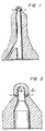
- fuel injector nozzles are machined with the critical flow metering orifices formed by conventional electrical discharge machining.
- the most critical flow resistance determinants are considered to be the diameter of orifices 10, 11, and wall thickness at section line A-A, as well as edge condition and surface roughness, including "lay" of the finish.
- the design specifications are for a wall thickness at this section of 1 mm ⁇ 0.05 mm (0.040 inches ⁇ 0.002 inches). Parts outside these specifications are rejected. Accepted parts are segregated in inventory into eight ranges, + 0.0065 mm (0.00025 inches).
- wall thickness at A-A is an indirect determinant of flow resistance of orifices 10, 11, and that the accurate control of the diameter of orifices 10, 11, is a direct determinant of flow resistance. These parameters determine flow metering properties, and a more direct measure of flow resistance of the part and a direct control in manufacture of such flow resistance is highly desirable.
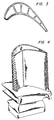
- FIGs. 3 and 4 Another example of flow resistance through an orifice of significant criticality is the provision of cooling air flow through gas turbine engine components, such as turbine blades.
- gas turbine engine components such as turbine blades.
- investment cast turbine blades are typically cast or drilled (by laser drilling, STEM drilling, or electrical discharge machining), to provide a plurality of holes, typically having a nominal diameter of about 0.3 to 0.8 mm (0.010 to 0.030 inches), passing from the interior passage to the vicinity of the leading edge, trailing edge, and elsewhere along the airfoil. Cooling air is forced from the interior, out the plural holes, and into the high temperature combustion gas stream to provide cooling of the blade. Sometimes holes through internal walls of the blade meter the distribution of cooling air.
- Another object is to provide such method whereby a plurality of flow controlling orifices can be provided with closely matched flow resistance.
- Still another object is to provide a method whereby a continuing plurality of parts can be made having predetermined flow resistance with high levels of precision and reproducibility.
- Yet another object is to provide a method of attaining a predetermined flow resistance through an orifice by controlling the orifice forming operation through a parameter which is a direct determinant of, or a direct consequent of flow resistance.
- the invention consists in the method of attaining a specific flow resistance of a fluid through an orifice in a structure by processing said orifice with a process utilizing a processing fluid, said process selected from the group consisting of a chemical machining, electrochemical machining, electrical discharge machining, electroplating, electroless plating and vapor deposition, wherein said processing fluid is caused to flow through said orifice by a mechanical pump, said method being characterised by comprising the following method steps :
- the present invention is based upon the action of electrochemical, chemical or electrical discharge machining (material removing techniques) or plating or coating (material building techniques) upon a part to provide a constant, predetermined rate of flow of the processing fluid used in said machining, plating or coating process, through an orifice, where the dynamic rate of the processing fluid is directly related to the target rate of flow through the orifice of the fluid of ultimate intended use.
- processing fluid is meant the liquid or gas that is utilized during the machining, plating or coating process, specifically, the electrolyte in the case of electrochemical machining and electroplating and electroless plating, the corrosive chemical solution whether caustic or acid in the case of chemical machining, the dielectric in the case of electrical discharge machining and the carrier gas in the case of vapor deposition.
- Processing as used herein is therefore limited to electrochemical, chemical and electrical discharge machining and to electroplating, electroless plating, or vapour deposition. It is possible to control the flow of the processing fluid by the application of a constant pressure or by a predetermined rate of displacement of a driving piston of constant area. Other methods to control the flow of the processing fluid are available depending on the means utilized to drive the processing fluid. If either pressure or flow rate is set, the other factor will be determined by processing fluid viscosity and orifice dimension and geometry.
- Fig. 1 is a cross-sectional view of a fuel injector metering nozzle.
- Fig. 2 is an enlarged detail view of a portion of Fig. 1, showing the metering orifices 10, 11.
- Fig. 3 is a cross-sectional view of a turbine blade showing cooling air metering orifices through the leading edge, trailing edge, air foil, and internal walls.
- Fig. 4 is a perspective view showing the overall configuration of the turbine blade of Fig. 3.
- Electrochemical, chemical and electrical discharge machining are widely employed procedures for working metals and related materials, particularly for machining and finishing operations on internal shapes, bores, apertures, complex three dimensional shapes, and other difficult operations.
- Electrochemical, and to a lesser extent chemical machining are used for deburring, radiusing, re-sizing, and polishing and finishing operations, often in internal shapes which are extremely difficult to process by other machining techniques, including orifices such as those which are the principal concern of the present invention. Electrochemical machining is also used for drilling. It is known that flow resistance through an orifice can be decreased by electrochemical, chemical and electrical discharge machining, and that an orifice can be enlarged by such operations.
- Electrochemical machining refers to machining operations performed by anodic reduction of the workpiece. This operation is effected by the application of an electrical potential across the gap separating the workpiece (anode) from the toolpiece (cathode) while forcing an electrolyte solution through said gap in order that an electrical current might flow between the two electrodes carrying material from the anode into the electrolyte, whereupon it is washed away.
- Chemical machining refers to machining operations performed by forcing a chemically corrosive fluid, either acid or caustic and either gaseous or liquid, which will chemically dissolve the material of the workpiece, across the surface which is to be machined in order to increase the rate of flow of liquids or gases in its ultimate intended use.
- a chemically corrosive fluid either acid or caustic and either gaseous or liquid
- Electrical discharge machining refers to machining operations performed by a succession of rapid electric spark discharges between a conductive tool and a conductive workpiece with a dielectric fluid circulated therebetween, whereby each discharge spark removes a small portion of the material of the workpiece across from the tool.
- a part or workpiece is fixed in a stationary tool and the processing fluid is hydraulically pumped through the passages formed by the part and its associated tooling at substantial pressure (and with appropriate applied electrical potential in the case of electrochemical and electrical discharge machining) until the desired degree of surface working is performed.
- Hydraulic cylinders or mechanical pumps are typically employed to pump said fluids through said passages.
- Electrochemical, chemical and electrical discharge machining as employed in the present invention do not include the flow of any physically abrasive materials, suspended, slurried or embedded, in fluid media such as cutting fluids, honing fluids, semisolid gels or gas streams and the like, but rather are limited to electrolyte or dielectric solutions solely for the purpose of electrical charge conduction or chemically corrosive fluids which operate by chemical attack upon the surface of the workpiece material.
- abrasive machining whether by gas suspension, liquid slurry or gel embedding of abrasive particles, have the shortcoming that harder materials require longer machining times and more rapid renewal of the abrasive material. Because the abrasive material is not easily filtered, it is possible for very small orifices that orifice opening can be blocked due to bridging of larger abrasive particles. Additionally gas suspension and liquid slurry abrasive particle machining exhibit limitations in directing the abrasive action to target surface areas within the flow channel where, due to turbulence, no particle flow is generated. In addition, cleaning of the finished workpiece is far easier with fluid processing than it is with abrasive flow. Still another possible disadvantage, and the most important, is that the abrasive filled fluid may not flow precisely like the fluid the orifice is intended to control.
- Electrochemical machining is a process ideally suited to many applications of finish machining.
- the conditions for electrochemical machining are mild (below 80°C) and the electrolyte solution can generally be 10% (w/w) sodium chloride or sodium nitrate in water. Electric potentials are kept below 50 volts, generating current densities typically no greater than about 0.65 ampere/mm2.
- Conditions of gap size (generally 0.025 - 0.50 mm) and current density appropriately set to prevent sparking, and adequate flow of electrolyte will yield controlled ablation of the workpiece surface, unaffected by material hardness. Nonuniformities are created by boundary layer electrolyte flow differences due to local turbulence and general flow rate through the channel.
- the rate of surface working is directly proportional to the chemical susceptibility of the material to the chemically corrosive fluid, rather than to the hardness of the material.
- the rate of chemical reaction can be controlled by corrosive agent concentration, flow rate and temperature.
- Working of the surface is essentially uniform except for variabilities in boundary layer thicknesses and mixing rates created by local turbulence and variations in the major flow rate across the surface, which is governed by cross-sectional area of the channel. Choosing proper etching parameters for the creation of a smooth, uniform surface are within the skill of those knowledgeable in the industry.
- Specific advantages to chemical machining include the ability to work materials which are not electrically conductive and the ability to use a gaseous machining fluid.
- the dielectric fluid is usually a hydrocarbon oil or deionized water which serves first to insulate the gap between the tool and workpiece, which subsequently becomes ionized when the electrical potential between the tool and workpiece reaches a given limit allowing the spark to discharge through the ionized dielectric.
- the flow of fresh dielectric fluid cools the tool and workpiece and again reinsulates the gap until the potential again reaches the given limit to permit the spark to discharge.
- Material removal rate as well as surface roughness both increase with increasing current or decreasing frequency.
- Electroplating, electroless plating and vapor deposition are widely employed procedures for adding finished surface layers of various metals, alloys or metal-nonmetal composites to either metallic or nonmetallic parts. Such metallic surface layers are primarily used to impart certain features of wear resistance, chemical inertness, electrical conductivity, magnetic properties or surface luster to the item being plated or coated where the desired finish is not a property of the part. Electroplating, electroless plating and vapor deposition are not generally considered to be techniques for finish sizing of orifices.
- Electroplating as employed in the present invention refers to plating operations performed by applying an electric potential across the gap separating the workpiece (cathode) and an anode.
- An electrolyte containing the ionized metal to be plated and appropriate buffering ions is circulated between the electrodes.
- the resultant flow of electric current causes reduction of the metallic ion at the surface of the cathode (workpiece), thus yielding a plating of the elemental metal.
- the thickness of the plated layer is a function of the plating time, electrical potential and ion concentration, and can be modulated by choosing appropriate plating conditions. The selection of these conditions is within the capacity of those skilled in the art. Virtually any metal which can be ionized is a potential candidate for electroplating applications.
- the primary shortcoming of electroplating techniques lies in their inherent inability to create a layer of deposited metal of uniform thickness. This is particularly the case with parts of nonuniform surface conformation, especially the internal surfaces of bores and chambers.
- electroplating the internal surfaces of bores or chambers can only be accomplished by the placement of auxiliary anodes within such interior bores or chambers uniformly spaced from the surfaces to be plated. This is particularly difficult for small bores and for irregular configurations.
- Electroless plating as employed in the present invention refers to processes of galvanic displacement and autocatalytic reduction of metal ions in an electrolyte solution in the absence of electric current, such that a layer of metal is deposited on surfaces exposed to said electrolyte solution.
- the electrolyte solution typically contains the metal cation and its anion, a reducing agent, an organic chelating agent such as EDTA, and a buffer, frequently a carboxylic acid salt.
- the most frequently used reducing agent is sodium hypophosphite, although sodium borhydride, amine boranes, and others can also be used.
- a characteristic of electroless plating is that coprecipitation of the desired metal and other components of the electrolyte occur.
- the coprecipitation is the phosphorus or boron of the reducing agent (approximately 10% of the deposited material).
- This "contamination,” though once a problem with the method, is now exploited to yield platings which are harder, or have other properties different from the electroplated counterpart.
- the coprecipitation process has been extended further to produce metallic layers with inclusions of particulate alumina, diamond, silicon carbide and other carbides for increased wear resistance, ceramics and plastics for individualized properties, and even PTFE to add lubricating properties to the surface. Heat treatments are frequently required to realize maximum hardness characteristics of the plate deposited by the electroless technique.
- Electroless plating is the method of choice for plating nonconductors of electricity, irregularly shaped parts, especially those with apertures, chambers and bores, because this process yields a uniform layer of metal (or composite) on all surfaces.
- Plating thickness is dependent upon the time and other factors associated with the electrolyte which are within the skill of the art to control.
- traditional control methods are not precise enough to yield plated parts with orifices delivering volumes of fluid within the constraints of uniformity necessary for the types of parts for which this invention applies. It is for this reason that plating techniques have not been employed for finish work on bored parts.
- electroless plating can bestow the dual advantages of plating an internal passage with a metal of choice, while producing an orifice with precise flow properties.
- the electroless plating technique is applicable to, but not limited to, plating of copper, nickel, gold, tungsten, palladium, tin, cobalt, zinc, zirconium, chromium, lead, cadmium, platinum, silver, aluminum, titanium and their alloys.
- Vapor deposition as employed in the present invention refers to the nonelectrolytic deposition of metals onto a substrate from a reactive vapor carried in a carrier gas, and is usually referred to as chemical vapor deposition. Vapor deposition processes which rely of conveyance of metal vapors through a vacuum would not be applicable to this invention.
- chemical vapor deposition the workpiece to be coated is placed in a sealed chamber and heated while a reactive vapor, typically consisting of a metal halide or carbonyl is carried therethrough with hydrogen gas. Deposition of the pure metal onto the workpiece occurs either by hydrogen reduction or thermal decomposition.
- the vapor deposition of compounds such as carbides, nitrides and borides can be effected by including reactive gases with the hydrogen such as methane, nitrogen and trichloride respectively.
- the workpiece For electroplating, electroless plating and vapor deposition in applications apropos to the present invention, the workpiece must be held in an apparatus such that the processing fluid flow is confined to passage through the orifice(s) to be plated or coated and sized. In addition, for electroplating the apparatus must be insulated for proper flow of electric current. Such techniques are within the skill of the industry.
- electrochemical, chemical and electrical discharge machining and plating and coating can be directly employed and controlled to govern flow resistance of an orifice by performing said machining, plating or coating operations to a predetermined rate of flow of processing fluid through the orifice at a constant applied pressure, or other equivalent determinant of the dynamic flow resistance of the orifice being sized. It has been observed that such flow resistance during the working operation is directly correlatable with flow resistance of other fluids through such an orifice, even at greatly different pressure. In addition, where minor discrepancies in such a correlation result in unacceptable variability, it is an aspect of the present invention to modulate the viscosity of the processing fluid to approximate as closely as possible the viscosity of the fluid of ultimate intended use under the intended environmental conditions.
- specific values of P o can be targeted by pumping the processing fluid with or without applied voltage at a constant velocity V o and continuing processing until the orifice pressure drops or rises to the target P o , depending upon whether the orifice is being machined or plated.
- Empirical determination of V o is readily obtained by selecting two prototypical parts having known orifices which provide known rates of flow of the intended working fluid under conditions of the intended working environment. By interpolation, these parts are employed as a comparative benchmark to measure V o at P o to establish the predetermined value of V o for use in processing with the proper processing fluid.
- V o V o ⁇ ⁇ ⁇ ⁇ ⁇ ⁇ ⁇ ⁇ ⁇ ⁇ ⁇ ⁇ ⁇ ⁇ ⁇ ⁇ ⁇ ⁇ ⁇ ⁇ ⁇ ⁇ ⁇ ⁇ ⁇ ⁇ ⁇ ⁇ ⁇ ⁇ ⁇ ⁇ ⁇ ⁇ ⁇ ⁇ ⁇ ⁇ ⁇ ⁇ ⁇ ⁇ ⁇ ⁇ ⁇ ⁇ ⁇ ⁇ ⁇ ⁇ ⁇ ⁇ ⁇ ⁇ ⁇ ⁇ ⁇ ⁇ ⁇ ⁇ ⁇ ⁇ ⁇ ⁇ ⁇ ⁇ ⁇ ⁇ ⁇ ⁇ ⁇ ⁇ ⁇ ⁇ ⁇ ⁇ ⁇ ⁇ ⁇ ⁇ ⁇ ⁇ ⁇ ⁇ ⁇ ⁇ ⁇ ⁇ ⁇ ⁇ ⁇ ⁇ ⁇ ⁇ ⁇ ⁇ ⁇ ⁇ ⁇ ⁇ ⁇ ⁇ ⁇ ⁇ ⁇ ⁇ ⁇ ⁇ ⁇ ⁇ ⁇ ⁇ ⁇ ⁇ ⁇ ⁇ ⁇ ⁇ ⁇ ⁇ ⁇ ⁇ ⁇
- a determination of the target V o and k benchmarks permits matching V o of a multiplicity of pieces to the target by measuring D p and t and computing kD p /t, and continuing the processing until the requisite value is attained.
- amper-seconds can be maintained as a constant value.
- P p is an independent variable in these processes and need not be maintained as constant. Equivalent results can be obtained if D p is maintained constant and P p is varied and measured in the operation or if both P p and D p are varied and measured simultaneously. Such operations are equivalent and are considered within the scope of the present invention.
- D p may not be the most accurate measure of moved processing fluid. Particularly for small orifices, therefore, a greater degree of accuracy may be achieved by directly measuring the volume or weight of the processing fluid passing through the orifice by other means.
- the orifice dimensions of the unworked workpieces or parts be sufficiently undersized in the case of electrochemical, chemical or electrical discharge machining, or oversized in the case of electroplating, electroless plating or coating so that substantially all workpieces or parts require, at least to a degree, machining, plating or coating to attain the target V o value. It is generally preferred but not essential that at least about 5 seconds of processing time be required so that there is some assurance of steady operating conditions of flow and measurement. This serves to minimize rejection of parts for oversize or undersize orifices, since processing is continued to the target V o .
- the amount of material to be removed by the electrochemical, chemical or electrical discharge machining operations or added by the plating or coating operations will, in most circumstances, be rather small, involving in most cases an enlargement or constriction of the diameter of the orifice on the order of less than a mil or a few mils or in some instances a few tens of mils.
- the radiusing of the entrance edge of the orifice alone is sufficient to significantly reduce or increase the flow resistance of the orifice.
- electrolyte solution current density, gap size and tool shape, for electrochemical machining, or the appropriate corrosive fluid, concentration and operating parameters for chemical machining, or appropriate current, dielectric fluid and discharge frequency for electrical discharge machining, or electrolyte concentration and field strength for electroplating, or electrolyte concentration for electroless plating, or carrier gas concentration for vapor deposition, these operations can be achieved in quite brief operating cycles. Care must be taken that the operating cycle is not so brief that the ability to measure and control is lost.
- the methods of the present invention operate to attain a specific dynamic property in the use of the orifice and not specific dimensions. For example, when the length of an orifice is greater than the designed value, due to a core shift in the casting operation for example, it will have a greater flow resistance than a short passage of exactly the same diameter. Pursuant to the above described methods of the present invention, longer passages will be enlarged more or plated less than short ones so that the resulting resistances to flow are equalized.
- the processes of this invention can be utilized to shorten longer passages or lengthen shorter passages to establish the desired resistance to flow without significantly affecting hole diameter.
- the interior chamber of the workpiece is preferentially machined, plated or coated for the purpose of reducing or increasing the wall thickness of the workpiece adjacent to the orifice having a flow resistance to be adjusted.
- this embodiment is based on the use of electrochemical, chemical or electrical discharge machining or plating or coating processes to shorten or enhance the workpiece wall thickness adjacent to the orifice of concern.
- the procedure is the same except that the machining, plating or coating is set up to machine, plate or coat the overlength or underlength wall while the processing fluid is passed through the the adjacent orifice while measuring its flow resistance.
- the flow resistance reaches its target value, the machining, plating or coating operation is stopped.
- the selective machining, plating or coating of one wall as opposed to the other is within the skill of the art.
- electrochemical machining, electric discharge machining and electroplating for example, the wall to be machined or plated can be preferentially machined or plated by maintaining the working cathode or tool closer to that wall than to the other.
- chemical machining, electroless plating and vapor deposition the wall not to be worked can be coated to prevent chemical attack thereon or plating thereon, or otherwise isolated from the process.
- the influence of various orifice conditions on the flow rate of the processing fluid may vary from that of the fluid the orifice is intended to meter. For instance, surface roughness, edge radius, and orifice diameter and length may affect flow of the processing fluids differently than the flow of air, water, or fuel.
- the primary difference between the fluids intended for use and the processing fluids is viscosity.
- the viscosity of any processing fluid may be increased or decreased by modifying or altering the composition of the solvent. This may include replacing all or part of one or more solvent components in the solution with another solvent, or by adding inert thinning or thickening components to the solution.
- the only specific limit on such modification of these solutions is that sufficient solvation of ions or corrosive chemical etc. must be retained for purposes of meeting the requirements of the machining, plating or coating process.
- the intended fluid for the part is a gas
- a corrosive gas or gas mixture can be used for the machining process, while vapor deposition would be the ideal choice for coating the orifice, thereby allowing accurate determination of V o values.
- an appropriate "test" fluid can be used to quantify the standard orifice.
- the "test" fluid flow information combined with the initial processing fluid flow rate can be incorporated into an algorithm that will target the processing fluid flow rate that will correspond to the target "test" fluid flow rate.
Landscapes
- Engineering & Computer Science (AREA)
- Mechanical Engineering (AREA)
- Physics & Mathematics (AREA)
- Thermal Sciences (AREA)
- Electrical Discharge Machining, Electrochemical Machining, And Combined Machining (AREA)
- Purification Treatments By Anaerobic Or Anaerobic And Aerobic Bacteria Or Animals (AREA)
- ing And Chemical Polishing (AREA)
- Machine Tool Sensing Apparatuses (AREA)
- Pipe Accessories (AREA)
Claims (24)
- Verfahren zum Erzielen eines bestimmten Durchflußwiderstandes hinsichtlich eines Fluids durch eine Öffnung in einem Bauteil durch Behandeln der besagten Öffnung mittels eines Arbeitsverfahrens, das ein Arbeits-Fluid verwendet, wobei das Arbeitsverfahren aus der Gruppe ausgewählt ist, die besteht aus: chemischer Bearbeitung, elektrochemischer Bearbeitung, Elektroerosions-Bearbeitung, Elektroplattieren, stromloses Plattieren und Aufdampfen od.dgl. von Überzügen, wobei ein Durchfluß des besagten Arbeits-Fluids durch die besagte Öffnung mittels einer mechanischen Pumpe bewirkt wird, gekennzeichnet durch die folgenden Verfahrens-Schritte:A. Bestimmen eines Soll-Durchflußwiderstandes hinsichtlich des besagten Arbeits-Fluids bei einem konstanten Wirkdruck, wie es den besagten bestimmten Durchflußwiderstand für das besagte Fluid liefern wird;B. Pumpen des besagten Arbeits-Fluids durch die besagte Öffnung mittels der besagten mechanischen Pumpe zum Behandeln der besagten Öffnung unter Aufrechterhaltung des besagten konstanten Wirkdruckes mit der besagten mechanischen Pumpe;C. Messen des dynamischen Durchflußwiderstandes des besagten Arbeits-Fluids durch die besagte Öffnung, während das besagte Arbeits-Fluid durch diese hindurchgepumpt wird, und Zulassen, daß sich die volumetrische Durchflußrate des besagten Arbeits-Fluids in direktem Verhältnis zu der an der besagten Öffnung bewirkten Behandlung ändert, zwecks Aufrechterhaltens des besagten konstanten Wirkdruckes mit der besagten Pumpe; undD. Beenden der Behandlung der besagten Öffnung, wenn der besagte dynamische Durchflußwiderstand gleich dem Soll-Durchflußwiderstand ist.
- Verfahren nach Anspruch 1, wobei der besagte Soll-Durchflußwiderstand von einem Master-Objekt her bestimmt wird.
- Verfahren nach Anspruch 2, wobei der besagte Soll-Durchflußwiderstand bestimmt wird durch Hindurchströmenlassen des besagten Arbeits-Fluids durch die besagte Öffnung bei vorbestimmtem festem Druck, während der dynamische Durchflußwiderstand des besagten Arbeits-Fluids durch die besagte Öffnung in dem besagten Master-Objekt gemessen wird.
- Verfahren nach Anspruch 1, wobei der besagte dynamische Durchflußwiderstand als eine Funktion der Geschwindigkeit des besagten Arbeits-Fluids durch die besagte Öffnung gemessen wird.
- Verfahren nach Anspruch 1, wobei der besagte dynamische Durchflußwiderstand als eine Funktion der volumetrischen Durchflußrate des besagten Arbeits-Fluids durch die besagte Öffnung gemessen wird.
- Verfahren nach Anspruch 1, dadurch gekennzeichnet, daß die mechanische Pumpe eine Pumpe mit verschiebbarem Kolben ist, der durch seine Verschiebung bewirkt, daß das besagte Arbeits-Fluid durch die besagte Öffnung strömt.
- Verfahren nach Anspruch 6, wobei der besagte dynamische Durchflußwiderstand als eine Funktion der axialen Verschiebung des besagten Kolbens pro zeitlicher Einheit gemessen wird.
- Verfahren nach Anspruch 6, wobei die besagte Funktion

- Verfahren nach Anspruch 8, wobei
- Verfahren nach Anspruch 6, wobei die zeitliche Einheit gleich oder kleiner als eine Sekunde ist.
- Verfahren nach Anspruch 6, wobei die zeitliche Einheit gleich oder kleiner als 0,1 Sekunde ist.
- Verfahren nach Anspruch 1, dadurch gekennzeichnet, daß anstelle des Fluid-Wirkdruckes die volumetrische Durchflußrate konstant gehalten wird und daß zugelassen wird, daß sich der Wirkdruck des besagten Arbeits-Fluids umgekehrt proportional zu der an der besagten Öffnung bewirkten Behandlung ändert, um die besagte konstante volumetrische Durchflußrate aufrechtzuerhalten.
- Verfahren nach Anspruch 12, wobei der besagte Soll-Durchflußwiderstand von einem Master-Objekt her bestimmt wird.
- Verfahren nach Anspruch 13, wobei der besagte Soll-Durchflußwiderstand durch Hindurchströmenlassen des besagten Arbeits-Fluids durch die besagte Öffnung mit der besagten vorbestimmten, festen volumetrischen Durchflußrate bestimmt wird, während der dynamische Durchflußwiderstand des besagten Arbeits-Fluids durch die besagte Öffnung in dem besagten Master-Objekt gemessen wird.
- Verfahren nach Anspruch 12, wobei der besagte dynamische Durchflußwiderstand als Funktion der Geschwindigkeit des besagten Arbeits-Fluids durch die besagte Öffnung gemessen wird.
- Verfahren nach Anspruch 12, wobei der besagte Durchfluß durch Verschiebung eines Kolbens erzeugt wird.
- Verfahren nach Anspruch 15, wobei der besagte dynamische Durchflußwiderstand als eine Funktion des Drukkes gemessen wird, der erforderlich ist, um eine konstante volumetrische Verschiebung des besagten Kolbens pro zeitlicher Einheit hervorzurufen.
- Verfahren nach Anspruch 12, wobei das besagte Fluid elektrolytische Lösungen, korrosive Fluide, dielektrische Fluide und Träger-Gase umfaßt.
- Verfahren nach Anspruch 12, wobei die besagte Behandlung eine elektrochemische Bearbeitung ist, und das besagte Arbeits-Fluid ein für die besagte elektrochemische Bearbeitung erforderlicher Elektrolyt ist.
- Verfahren nach Anspruch 12, wobei die besagte Behandlung eine chemische Bearbeitung ist, und das besagte Arbeits-Fluid ein für die besagte chemische Bearbeitung erforderliches korrosives Fluid ist.
- Verfahren nach Anspruch 12, wobei die besagte Behandlung eine elektroerosive Bearbeitung ist, und das besagte Arbeits-Fluid ein für die besagte elektroerosive Bearbeitung erforderliches dielektrisches Fluid ist.
- Verfahren nach Anspruch 12, wobei die besagte Behandlung ein Elektroplattieren ist, und das besagte Arbeits-Fluid ein für das besagte Elektroplattieren erforderlicher Elektrolyt ist.
- Verfahren nach Anspruch 12, wobei die besagte Behandlung ein stromloses Herstellen eines Überzuges ist, und das besagte Arbeits-Fluid ein für das besagte stromlose Überziehen erforderlicher Elektrolyt ist.
- Verfahren nach Anspruch 12, wobei die besagte Behandlung ein Herstellen eines Überzuges durch Auf- bzw. Bedampfen ist, und das besagte Arbeits-Fluid ein für das besagte Aufdampfen erforderliches Träger-Gas ist.
Applications Claiming Priority (3)
| Application Number | Priority Date | Filing Date | Title |
|---|---|---|---|
| US265934 | 1988-11-02 | ||
| US07/265,934 US4995949A (en) | 1986-03-21 | 1988-11-02 | Orifice sizing using chemical, electrochemical, electrical discharge machining, plating, coating techniques |
| PCT/US1989/004870 WO1990005039A1 (en) | 1988-11-02 | 1989-11-02 | Method of processing orifices |
Publications (3)
| Publication Number | Publication Date |
|---|---|
| EP0441887A1 EP0441887A1 (de) | 1991-08-21 |
| EP0441887A4 EP0441887A4 (en) | 1991-11-13 |
| EP0441887B1 true EP0441887B1 (de) | 1994-06-29 |
Family
ID=23012482
Family Applications (1)
| Application Number | Title | Priority Date | Filing Date |
|---|---|---|---|
| EP89912994A Expired - Lifetime EP0441887B1 (de) | 1988-11-02 | 1989-11-02 | Verfahren zur behandlung von löchern |
Country Status (6)
| Country | Link |
|---|---|
| US (1) | US4995949A (de) |
| EP (1) | EP0441887B1 (de) |
| JP (1) | JPH04502886A (de) |
| AT (1) | ATE107882T1 (de) |
| DE (1) | DE68916552T2 (de) |
| WO (1) | WO1990005039A1 (de) |
Cited By (2)
| Publication number | Priority date | Publication date | Assignee | Title |
|---|---|---|---|---|
| DE10204952A1 (de) * | 2002-02-04 | 2003-08-21 | Extrude Hone Gmbh | Verfahren und Vorrichtung zum Erzielen eines bestimmten Durchflusswiderstandes eines Strömungskanals |
| DE10204561A1 (de) * | 2002-02-04 | 2003-08-21 | Extrude Hone Gmbh | Verfahren und Vorrichtung zum Erzielen eines bestimmten Durchflusswiderstandes eines Strömungskanals mit Hilfe einer Messbrücke |
Families Citing this family (35)
| Publication number | Priority date | Publication date | Assignee | Title |
|---|---|---|---|---|
| US5373449A (en) * | 1988-08-13 | 1994-12-13 | Amchem Company Limited | Method of producing a multi-apertured workpiece |
| US5034106A (en) * | 1990-08-16 | 1991-07-23 | General Motors Corporation | Electrolytic drilling |
| DE4307159B4 (de) * | 1993-03-06 | 2009-03-26 | Robert Bosch Gmbh | Spritzlochscheibe für ein Ventil und Verfahren zur Herstellung |
| US5306401A (en) * | 1993-03-15 | 1994-04-26 | Fierkens Richard H J | Method for drilling cooling holes in turbine blades |
| US5435884A (en) * | 1993-09-30 | 1995-07-25 | Parker-Hannifin Corporation | Spray nozzle and method of manufacturing same |
| US5522760A (en) * | 1994-08-22 | 1996-06-04 | Cummins Engine Company, Inc. | Method of microdeburring a bore |
| DE4437624A1 (de) * | 1994-10-21 | 1996-04-25 | Frembgen Fritz Herbert | Verfahren zum elektrochemischen Bearbeiten von Strömungskanälen metallischer Werkstücke |
| US5702288A (en) * | 1995-08-30 | 1997-12-30 | United Technologies Corporation | Method of removing excess overlay coating from within cooling holes of aluminide coated gas turbine engine components |
| US5893984A (en) * | 1995-10-27 | 1999-04-13 | General Electric Company | High aspect ratio EDM electrode assembly |
| FR2742255B1 (fr) * | 1995-12-08 | 1998-03-06 | Framatome Sa | Procede et dispositif de deconfinement du logement d'une vis d'assemblage de deux plaques planes du cloisonnement du coeur d'un reacteur nucleaire |
| JPH09225750A (ja) * | 1996-02-19 | 1997-09-02 | Hoden Seimitsu Kako Kenkyusho Ltd | 放電加工方法およびその装置 |
| ES2127585T3 (es) * | 1996-04-20 | 1999-04-16 | Frembgen Fritz Herbert | Procedimiento para el mecanizado electroquimico de canales de paso en piezas metalicas. |
| US5820744A (en) * | 1996-09-30 | 1998-10-13 | Doncasters, Turbo Products Division | Electrochemical machining method and apparatus |
| JP2002536549A (ja) * | 1999-02-12 | 2002-10-29 | ゲレスト インコーポレイテッド | 窒化タングステンの化学蒸着 |
| US6539627B2 (en) | 2000-01-19 | 2003-04-01 | General Electric Company | Method of making turbulated cooling holes |
| US6735950B1 (en) * | 2000-03-31 | 2004-05-18 | General Electric Company | Combustor dome plate and method of making the same |
| DE10048935A1 (de) * | 2000-10-04 | 2002-04-11 | Bosch Gmbh Robert | Brennstoffeinspritzventil |
| US20050029109A1 (en) * | 2002-05-07 | 2005-02-10 | Gang Zhang | Method of electrochemically fabricating multilayer structures having improved interlayer adhesion |
| US20050045585A1 (en) * | 2002-05-07 | 2005-03-03 | Gang Zhang | Method of electrochemically fabricating multilayer structures having improved interlayer adhesion |
| WO2004101862A1 (en) * | 2003-05-07 | 2004-11-25 | Microfabrica Inc. | Method of electrochemically fabricating multilayer structures having improved interlayer adhesion |
| JP4215677B2 (ja) * | 2003-08-25 | 2009-01-28 | 日立ビアメカニクス株式会社 | レーザ加工機及びレーザ加工方法 |
| US6991425B2 (en) * | 2003-09-12 | 2006-01-31 | Honeywell International, Inc. | Air turbine starter with unitary inlet and stator |
| US20060042932A1 (en) * | 2004-08-25 | 2006-03-02 | Rosenzweig Mark A | Apparatus and method for electroplating a workpiece |
| US20060073348A1 (en) * | 2004-10-06 | 2006-04-06 | General Electric Company | Electroplated fuel nozzle/swirler wear coat |
| EP1655091A1 (de) * | 2004-11-09 | 2006-05-10 | Siemens Aktiengesellschaft | Verfahren zur elektrolytischen Bearbeitung eines Bauteils und ein Bauteil mit Durchgangsloch |
| EP1655092A1 (de) * | 2004-11-09 | 2006-05-10 | Siemens Aktiengesellschaft | Verfahren zur elektrolytischen Bearbeitung eines Bauteils mit Durchgangsloch |
| AU2006204976B2 (en) * | 2005-01-12 | 2010-08-19 | Lummus Technology Inc. | Methods and apparatus for improved control of PSA flow variations |
| GB2428608A (en) * | 2005-07-30 | 2007-02-07 | Siemens Ind Turbomachinery Ltd | A method for production of a set of holes by monitoring fluid flow |
| JP4569462B2 (ja) * | 2005-12-19 | 2010-10-27 | 株式会社デンソー | 流体研磨加工方法及び装置 |
| KR20090106641A (ko) * | 2007-01-29 | 2009-10-09 | 토소우 에스엠디, 인크 | 극도로 매끄러운 면의 스퍼터 타겟 및 그 제조 방법 |
| US20080230396A1 (en) * | 2007-03-22 | 2008-09-25 | General Electric Company | Methods and systems for forming turbulated cooling holes |
| US10533439B2 (en) * | 2014-12-16 | 2020-01-14 | United Technologies Corporation | Gas turbine engine component with abrasive surface formed by electrical discharge machining |
| CN104625263B (zh) * | 2015-01-19 | 2017-02-22 | 同济大学 | 一种基于凝胶电化学加工的肋化内冷却结构冷却管的制备方法 |
| WO2017142882A1 (en) * | 2016-02-15 | 2017-08-24 | Rem Technologies, Inc. | Chemical processing of additive manufactured workpieces |
| DE102018203065A1 (de) * | 2018-03-01 | 2019-09-05 | Robert Bosch Gmbh | Verfahren zur Herstellung eines Injektors |
Family Cites Families (12)
| Publication number | Priority date | Publication date | Assignee | Title |
|---|---|---|---|---|
| US2570624A (en) * | 1946-11-19 | 1951-10-09 | Gulf Research Development Co | Follow-up pneumatic servomotor |
| US2687147A (en) * | 1949-03-29 | 1954-08-24 | Us Quarry Tile Company | Orifice construction |
| US3349619A (en) * | 1959-07-29 | 1967-10-31 | Meriam Instr Company | Laminar flow element and flow meter |
| US3228863A (en) * | 1960-10-27 | 1966-01-11 | Gen Motors Corp | Electrolytic process and apparatus for removing stock from a conductive workpiece |
| US3399125A (en) * | 1964-01-28 | 1968-08-27 | Hitachi Ltd | Electrochemical machining in a pressurized chamber substantially without the formation of gas bubbles |
| US3480530A (en) * | 1966-11-15 | 1969-11-25 | Gen Motors Corp | Method for producing porous metal parts having uniform fluid permeability |
| SU395246A1 (ru) * | 1969-05-12 | 1973-08-28 | Способ гидроабразивной обработки сопловых | |
| US3753879A (en) * | 1971-02-03 | 1973-08-21 | Ass Eng Ltd | Method and means for producing holes |
| SU518326A2 (ru) * | 1975-02-21 | 1976-06-25 | Алтайский Моторный Завод | Устройство дл автоматического отключени подачи суспензии при гидроабразивной обработке отверстий |
| US4147481A (en) * | 1977-08-19 | 1979-04-03 | Deutsch Daniel Harold | Asymmetric permeable member |
| US4455470A (en) * | 1981-08-14 | 1984-06-19 | The Perkin-Elmer Corporation | Plasma spray gun nozzle and coolant deionizer |
| US4578164A (en) * | 1983-08-24 | 1986-03-25 | Nissan Motor Co., Ltd. | Method of electrolytically finishing spray-hole of fuel injection nozzle |
-
1988
- 1988-11-02 US US07/265,934 patent/US4995949A/en not_active Expired - Lifetime
-
1989
- 1989-11-02 EP EP89912994A patent/EP0441887B1/de not_active Expired - Lifetime
- 1989-11-02 JP JP2500337A patent/JPH04502886A/ja active Pending
- 1989-11-02 AT AT89912994T patent/ATE107882T1/de active
- 1989-11-02 DE DE68916552T patent/DE68916552T2/de not_active Expired - Fee Related
- 1989-11-02 WO PCT/US1989/004870 patent/WO1990005039A1/en not_active Ceased
Cited By (2)
| Publication number | Priority date | Publication date | Assignee | Title |
|---|---|---|---|---|
| DE10204952A1 (de) * | 2002-02-04 | 2003-08-21 | Extrude Hone Gmbh | Verfahren und Vorrichtung zum Erzielen eines bestimmten Durchflusswiderstandes eines Strömungskanals |
| DE10204561A1 (de) * | 2002-02-04 | 2003-08-21 | Extrude Hone Gmbh | Verfahren und Vorrichtung zum Erzielen eines bestimmten Durchflusswiderstandes eines Strömungskanals mit Hilfe einer Messbrücke |
Also Published As
| Publication number | Publication date |
|---|---|
| ATE107882T1 (de) | 1994-07-15 |
| DE68916552T2 (de) | 1995-02-23 |
| EP0441887A1 (de) | 1991-08-21 |
| JPH04502886A (ja) | 1992-05-28 |
| US4995949A (en) | 1991-02-26 |
| DE68916552D1 (de) | 1994-08-04 |
| EP0441887A4 (en) | 1991-11-13 |
| WO1990005039A1 (en) | 1990-05-17 |
Similar Documents
| Publication | Publication Date | Title |
|---|---|---|
| EP0441887B1 (de) | Verfahren zur behandlung von löchern | |
| US5514422A (en) | Composite metallizing wire and method of using | |
| Rajurkar et al. | New developments in electro-chemical machining | |
| Painuly et al. | Electrochemical machining and allied processes: a comprehensive review | |
| Kumar et al. | Research developments in additives mixed electrical discharge machining (AEDM): a state of art review | |
| Furutani et al. | Influence of electrical conditions on performance of electrical discharge machining with powder suspended in working oil for titanium carbide deposition process | |
| Rajurkar et al. | Improvement of electrochemical machining accuracy by using orbital electrode movement | |
| Lin et al. | Surface improvement using a combination of electrical discharge machining with ball burnish machining based on the Taguchi method | |
| US3352770A (en) | Electrochemical machining of small diameter holes in high temperature superalloys | |
| Nguyen et al. | Die steel surface layer quality improvement in titanium μ-powder mixed die sinking electrical discharge machining | |
| US5976704A (en) | Composite metallizing wire and method of using | |
| CN106312208B (zh) | 辅助阳极电解磨铣加工系统及方法 | |
| US3769194A (en) | Apparatus and method for forming grooves and lands | |
| EP0277957B1 (de) | Verfahren zur steuerung des fliesswiderstandes bei der herstellung einer flüssigkeitsdüse | |
| Brown | Modern manufacturing processes | |
| Hocheng et al. | Development of the eroded opening during electrochemical boring of hole | |
| EP1662022A1 (de) | Vorrichtung und verfahren zum beschichten mittels elektrischer entladung | |
| Zyhulia et al. | Effect of the integrated treatment on the manufacturing of printing cylinders | |
| Tang et al. | Precision wire electrochemical machining of thick structures in powder superalloy René 88DT using a partially insulated tube electrode | |
| US3630878A (en) | Apparatus and method for forming grooves and lands | |
| US8455783B2 (en) | Electro-erosion edge honing of cutting tools | |
| Lievestro | Electrochemical machining | |
| Bergs et al. | Electrical Discharge Machining (EDM) | |
| Shestakov et al. | Capabilities of electrochemical dimensional machining of thin-walled oversized aircraft details using rotating cathode-instrument | |
| Hoare et al. | Electrochemical Machining |
Legal Events
| Date | Code | Title | Description |
|---|---|---|---|
| PUAI | Public reference made under article 153(3) epc to a published international application that has entered the european phase |
Free format text: ORIGINAL CODE: 0009012 |
|
| 17P | Request for examination filed |
Effective date: 19910501 |
|
| AK | Designated contracting states |
Kind code of ref document: A1 Designated state(s): AT CH DE FR GB IT LI SE |
|
| RHK1 | Main classification (correction) |
Ipc: B23H 9/14 |
|
| A4 | Supplementary search report drawn up and despatched |
Effective date: 19910925 |
|
| AK | Designated contracting states |
Kind code of ref document: A4 Designated state(s): AT CH DE FR GB IT LI SE |
|
| 17Q | First examination report despatched |
Effective date: 19920519 |
|
| GRAA | (expected) grant |
Free format text: ORIGINAL CODE: 0009210 |
|
| AK | Designated contracting states |
Kind code of ref document: B1 Designated state(s): AT CH DE FR GB IT LI SE |
|
| PG25 | Lapsed in a contracting state [announced via postgrant information from national office to epo] |
Ref country code: IT Free format text: LAPSE BECAUSE OF FAILURE TO SUBMIT A TRANSLATION OF THE DESCRIPTION OR TO PAY THE FEE WITHIN THE PRESCRIBED TIME-LIMIT;WARNING: LAPSES OF ITALIAN PATENTS WITH EFFECTIVE DATE BEFORE 2007 MAY HAVE OCCURRED AT ANY TIME BEFORE 2007. THE CORRECT EFFECTIVE DATE MAY BE DIFFERENT FROM THE ONE RECORDED. Effective date: 19940629 Ref country code: FR Effective date: 19940629 Ref country code: LI Effective date: 19940629 Ref country code: CH Effective date: 19940629 Ref country code: AT Effective date: 19940629 |
|
| REF | Corresponds to: |
Ref document number: 107882 Country of ref document: AT Date of ref document: 19940715 Kind code of ref document: T |
|
| REF | Corresponds to: |
Ref document number: 68916552 Country of ref document: DE Date of ref document: 19940804 |
|
| PG25 | Lapsed in a contracting state [announced via postgrant information from national office to epo] |
Ref country code: SE Effective date: 19940929 |
|
| REG | Reference to a national code |
Ref country code: CH Ref legal event code: PL |
|
| EN | Fr: translation not filed | ||
| PLBE | No opposition filed within time limit |
Free format text: ORIGINAL CODE: 0009261 |
|
| STAA | Information on the status of an ep patent application or granted ep patent |
Free format text: STATUS: NO OPPOSITION FILED WITHIN TIME LIMIT |
|
| 26N | No opposition filed | ||
| REG | Reference to a national code |
Ref country code: GB Ref legal event code: IF02 |
|
| PGFP | Annual fee paid to national office [announced via postgrant information from national office to epo] |
Ref country code: DE Payment date: 20071025 Year of fee payment: 19 |
|
| PGFP | Annual fee paid to national office [announced via postgrant information from national office to epo] |
Ref country code: GB Payment date: 20071031 Year of fee payment: 19 |
|
| GBPC | Gb: european patent ceased through non-payment of renewal fee |
Effective date: 20081102 |
|
| PG25 | Lapsed in a contracting state [announced via postgrant information from national office to epo] |
Ref country code: DE Free format text: LAPSE BECAUSE OF NON-PAYMENT OF DUE FEES Effective date: 20090603 |
|
| PG25 | Lapsed in a contracting state [announced via postgrant information from national office to epo] |
Ref country code: GB Free format text: LAPSE BECAUSE OF NON-PAYMENT OF DUE FEES Effective date: 20081102 |