EP0441896B1 - Verfahren zur umwandlung und behandlung verdichteter bilddaten zu mehrfachen formaten - Google Patents
Verfahren zur umwandlung und behandlung verdichteter bilddaten zu mehrfachen formaten Download PDFInfo
- Publication number
- EP0441896B1 EP0441896B1 EP90901108A EP90901108A EP0441896B1 EP 0441896 B1 EP0441896 B1 EP 0441896B1 EP 90901108 A EP90901108 A EP 90901108A EP 90901108 A EP90901108 A EP 90901108A EP 0441896 B1 EP0441896 B1 EP 0441896B1
- Authority
- EP
- European Patent Office
- Prior art keywords
- code
- image
- list
- scan line
- converting
- Prior art date
- Legal status (The legal status is an assumption and is not a legal conclusion. Google has not performed a legal analysis and makes no representation as to the accuracy of the status listed.)
- Expired - Lifetime
Links
Images



Classifications
-
- G—PHYSICS
- G06—COMPUTING OR CALCULATING; COUNTING
- G06T—IMAGE DATA PROCESSING OR GENERATION, IN GENERAL
- G06T9/00—Image coding
- G06T9/005—Statistical coding, e.g. Huffman, run length coding
-
- H—ELECTRICITY
- H04—ELECTRIC COMMUNICATION TECHNIQUE
- H04N—PICTORIAL COMMUNICATION, e.g. TELEVISION
- H04N1/00—Scanning, transmission or reproduction of documents or the like, e.g. facsimile transmission; Details thereof
- H04N1/41—Bandwidth or redundancy reduction
- H04N1/411—Bandwidth or redundancy reduction for the transmission or storage or reproduction of two-tone pictures, e.g. black and white pictures
- H04N1/413—Systems or arrangements allowing the picture to be reproduced without loss or modification of picture-information
Definitions
- This invention relates to image data processing and more particularly to converting between image data of a plurality of differing formats. Specifically, the invention relates to the conversion between defined forms of standardized image data, wherein one form involves single-line coding and another form involves multiple-line coding in a manner optimized for speed of processing.
- the invention has particular application in facsimile data transmission and in bit-mapped image reproduction, such as in connection with electrostatic (laser) graphics printers.
- Image data is an important data form for conveying information of both text and graphic content.
- the current market for laser printers alone is valued at more than one billion dollars.
- the facsimile market has a similar large market value.
- Image data is typically coded as either a compressed code or a bit-mapped code.
- a single standard page-sized bit-mapped data image having a resolution of 400 lines per inch requires sixteen million bits of storage. Transmission of a bit-mapped image a bit at a time over conventional telephone-grade 3000 Hz bandwidth communication media is considered to be prohibitively time-consuming.
- image data is reduced to one of several types of compressed code form, such as Group III (Modified Huffman or MH) or Group IV (MMR) prior to transmission.
- Group III Modified Huffman or MH
- MMR Group IV
- DE-A-3 512 070 discloses a method for converting a first image described by a first graphics image code to a corresponding image described by a second graphics image code by utilizing an intermediate code which is manipulated.
- the intermediate code is a compression code representing run length of either "black” or "white” picture elements.
- a method for converting an image from a binary bit map representation to a run length representation is known from US-A-4 646 356.
- the known method includes the step of accessing for each byte in the image by a look-up table a selected routine for converting bit strings to run representations.
- bit-mapped image data as well as selected forms of compressed image data, are converted between one another by converting data through an intermediate data and code structure wherein each image is represented by a list of sublists, each sublist being itself a list of numerical values representing run lengths between transitions from one type of picture element (pel) to a second and opposite type of picture element (pel) (e.g., a black pel and a white pel).
- the intermediate code data structure according to the invention is termed a transition list or TL code or data structure.
- the data structure and coding rules are defined by rules relating to code type, code word length and code word interdependence.
- a specific conversion process specifies that the transition list be composed of sublists wherein each represents a scan line.
- the rules specify 1) that the intermediate code be a run length-type code of each scan line of the image, 2) that the code words be of fixed length and 3) that the image be stored in a (two-dimensional) serial array wherein each scan line is of a length dependent only on the number of transitions of run lengths.
- the preferred form of intermediate code is a fixed word-length transition list, that is, a serial list of values representing run lengths of either "black" picture elements or "white” picture elements stored serially in digital data format having a fixed word length, wherein the last value is repeated three times to indicate end of line.
- a scan line header word may specify scan line length.
- a specific conversion process specifies that the transition list be composed of sublists representing a scan line, each scan line consisting of a header word indicating line length from zero to a value indicating page width, and a grouping (in pairs) of words specifying run lengths of white pels and run lengths of black pels.
- a rule specifies 1) that a full transition list (a page) have a scan line header word specifying the number of transitions (an even number), 2) that the first run length code word be the incremental (rather than cumulative) number of consecutive white picture elements (stored in a two-byte word), 3) that the second run length code word be the incremental (rather than cumulative) number of consecutive black picture elements (stored in a two-byte word), 4) that the last run length code word be a black run length code, thus pairing white and black run length units and skipping the final white code word in each scan line, 5) that the end-of-segment (or end-of-image) marker be a negative one (-1) stored in a two-byte word, 6) that the segment header word be a two-byte word specifying the address of the next segment of memory, or that there is no further segment, and finally 7) that the image header consist of five two-byte words specifying a) height of the image in lines, b) width in maximum number of picture elements, c) vertical
- the invention further contemplates processes for converting from MH to TL, from TL to MH, from MMR to TL, from TL to MMR, from text to TL, from TL to printable bit-mapped image, from TL to displayable bit-mapped image, and from scanned bit-mapped image to TL.
- the intermediate code according to the invention is of a form sufficiently compressed and sufficiently modularized that important and desired intermediate processes can be applied to it, such as image merging, image scaling and image cut and paste.
- important and desired intermediate processes can be applied to it, such as image merging, image scaling and image cut and paste.
- the processes according to the invention contemplate TL merge, TL scaling and TL cutout.
- a typical compressed data image of a page of text contains a limited number of transitions between "black” and “white” in the course of a serial scan of a pictorial image.
- a typical image with a resolution of 300 to 400 lines per inch contains only about 160,000 transitions. Recognizing these and other characteristics makes it possible to produce a homogeneous image output suitable for either facsimile transmission or for hard-copy image reproduction. It could well emerge that a standard form of information may emerge comprising a hybrid of electronic data and electronic image. This invention permits rapid processing and merging of such a form into a final hard copy form, and it permits transmission of an electronic image of such information in a standard facsimile format.
- the invention has been found to be capable of processing a page of information at a rate of 4 seconds per page using conventional facsimile processing hardware such as the Am7970A compression expansion processor chip built by Advanced Micro Devices of Sunnyvale, California in conjunction with an 80286 microprocessor chip of Intel Corporation of Santa Clara, California.
- a conventional process using the same hardware would require about 60 seconds per page.
- Conventional image processing employing faster hardware, such that based on as a 68020 microprocessor chip of Motorola Corporation of Chicago, Illinois, are able to achieve a speed of about 15 seconds per page. Nevertheless, the present invention is able to produce its results with less than one one-hundredth of the processing power which would be required for full bit-mapped image processing.
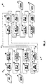
- Figure 1 is a block diagram of a specific embodiment of the invention illustrating data conversion elements, data storage elements, data manipulation elements and data transmission and reception elements.
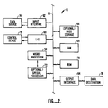
- Figure 2 is a simplified block diagram of a digital data processing apparatus for use in an apparatus according to the invention.
- Figure 3 is a diagram illustrating a specific embodiment of a transition list as stored in a block of a digital memory.
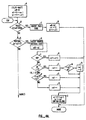
- Figures 4A and 4B together are a flow chart of a process for converting transition list data into MMR data.
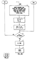
- Figure 5 is a flow chart of a process for converting transition list data into MH data.
- Figure 6 is a flow chart of a process for converting transition list data into MR data.
- Figures 7A, 7B and 7C together are a flow chart of a process for converting MMR data into transition list data.
- FIG. 1 there is shown a block diagram of a specific embodiment of an encoding/decoding apparatus 10 in accordance with the invention.
- the encoding/decoding apparatus 10 comprises an encoder 12, a modem (and transmission medium) 14 and a decoder 16.
- the modem 14 as coupled to a transmission medium is illustrated for the sake of completeness and is not an essential element to the understanding of the invention.
- the modem (and transmission medium) 14 comprise for example an MMR modulator 18 coupled to a suitable transmission link 20, such as a 64 KBS transmission link suited to carrying standard MMR modulation as defined in CCITT Recommendation T.6 "FACSIMILE CODING SCHEMES AND CODING CONTROL FUNCTIONS FOR GROUP 4 FACSIMILE APPARATUS," Fascicle VII.3 - Rec. T.6 (Malaga-Torremolinos, 1984).
- the transmission link 20 is coupled to an MMR demodulator 22.
- the MMR modulator 18 is coupled to receive MMR data from a suitable data buffer or memory, such as a two-port MMR memory 24.
- the MMR demodulator 22 is coupled to a suitable two-port MMR memory 26 which is operative to capture received and demodulated MMR data in order to buffer it for further processing in accordance with the invention.
- each terminal of a facsimile network employing an apparatus in accordance with the invention comprise the three elements of an encoder 12, a modem 14 and a decoder 16.
- an apparatus is capable of communication with any other Group 4 apparatus through its modulator 18 and demodulator 22.
- the encoder 12 is suited to receive at its input 28 digital information which does not have a one-for-one correspondence with a target code such as MMR (CCITT Group 4 facsimile code) and to convert that source information through a transition list processor 30 into a transition list code, and thereafter to process the information in the transition list code through a transition list processor 32 and/or convert the transition list code through a transition list to output code converter 34 into a target code such as MMR code.
- a target code such as MMR (CCITT Group 4 facsimile code)
- the input digital information of an encoder 12 in accordance with the invention may be MH code (CCITT Group 3 facsimile code as defined CCITT Recommendation T.4 "STANDARDIZATION OF GROUP 3 FACSIMILE APPARATUS FOR DOCUMENT TRANSMISSION," Fascicle VII.3 - Rec. T.4, Geneva, 1980, amended at Malaga-Torremolinos, 1984), bit-mapped image data, text code, such as USASCII or EBCDIC, or eventually even an image description in a printer description language code such as DDL (Data Description Language of Imagen Corporation) or PostScript of Adobe Systems.
- MH code CITT Group 3 facsimile code as defined CCITT Recommendation T.4 "STANDARDIZATION OF GROUP 3 FACSIMILE APPARATUS FOR DOCUMENT TRANSMISSION," Fascicle VII.3 - Rec. T.4, Geneva, 1980, amended at Malaga-Torremolinos, 1984
- bit-mapped image data such
- the input 28 is coupled to an input memory 36 which in turn is coupled to the input to transition list processor 30, the output of which is coupled to a first transition list memory 38.
- the first transition list memory 38 is coupled to the transition list code to transition list code processor 32, which in turn is coupled to the second transition list memory 39.
- the second transition list memory is coupled to the transition list to output code (MMR) converter 34, which in turn is coupled to provide output code to the MMR memory 24 of the modem 14.
- First control means 40 are provided for controlling the nature of processes carried out by the transition list processor 32, such as merge, scaling or cutout.
- the various memory means are provided for temporary storage of code during processing. It is contemplated that the apparatus 12 will operate in near real time, and that the memory means are adapted to high throughput applications.
- the memory means may be embodied in a signal physical memory unit, such as a semiconductor random access memory device, or into a plurality of memory units serving as two-port input-output buffer memories.
- the processors 30, 32, and 34 may be embodied in a programmable microprocessor unit operative to execute computer programs for performing the input to transition list conversions, the transition list to transition list manipulations and the transition list to output code conversions. Suitable microprocessors for commercial applications of the invention are the Motorola 68000 series microprocessors.
- the operations of the microprocessor may be augmented by conventional facsimile processing hardware such as the Am7970A compression/expansion processor chip built by Advanced Micro Devices of Sunnyvale, California in conjunction with an 80286 microprocessor chip of Intel Corporation of Santa Clara, California.
- the decoder 16 is suited to convert received source code from the modem 14, typically in a code such as MMR, through the mechanism of a source code to transition list converter 42 into a transition list code and thereafter to process the transition list code in a transition list code processor 44 under control of a second control apparatus 45 and/or convert the transition list encoded data via a transition list code to output code processor 46 into a target code for transmission to an output apparatus 48, such as a printer, a display or another facsimile transmitter.
- the target code may be a bit-mapped image, text, MH code or a printer description language code. Images for display may be bit-mapped code or text code. Images for printing may be PDL code, text code or bit mapped code.
- Images for transmission into another media such as according to a different facsimile standard may be converted into a facsimile code such as MH code or some other compressed image code. It is important to recognize that according to the present invention, there need not be a direct correlation between the source code and the target code, so long as a conversion exists whereby image data can be converted into and out of transition lists
- a third transition list memory 50 In order to provide temporary storage conversion and manipulation processes, a third transition list memory 50, a fourth transition list memory 52 and an output memory 54 are provided between the processors as above. It is contemplated that many of these functions are shared by the same physical elements and further that subsets of the apparatus as shown in Figure 1 may be provided for dedicated and special purpose functions where not all of the options as illustrated are needed or used.
- FIG. 2 is a block diagram of a typical microprocessor-based apparatus 10 incorporating the features of the present invention.
- the apparatus 10 comprises a data and control bus 56 to which are coupled a central processing unit, i.e., a microprocessor 58, input/output channels 60, a data input interface 62, a data output interface 64, mass storage 66, random access memory 68, read only memory 70 and a special processor 72.
- a data source 74 is coupled to provide source data through the input interface 62 to the random access memory 68 under control of the microprocessor 58, and a data destination 76 is coupled to receive destination date via the output interface 64 under control of the microprocessor 58.
- a control device 78 such as a terminal or remote data link, provides overall command and control via the input/output interface 60.
- Special processing of facsimile data is for example, handled by the dedicated processor 72 coupled in accordance with the specifications for the dedicated processor to the bus 56 and the microprocessor 58. It should be understood that other structures may be employed, such as a structure employing pipeline memory, cache memory or other structures determined to be suited to processing of facsimile image data.
- a transition list 80 comprises a superheader 82, a segment header 84 and a plurality of segments or transition sublists 86, 88, 90, 92, 94, 96, and 98 and an end of segment block marker 100.
- the transition list 80 represents the complete description of an image independent of the compressed code or bit image representation of the image.
- Each of the segments or sublists 86, 88, 90, 92, 94, 96, and 98 is a fixed bit-length number representing the number of consecutive bits in the scan line of an image without transition the absence of an image registration and the presence of an image registration, e.g., the number of consecutive bits transitions from white to black and from black to white in a black and white image.
- Color images may be represented in a similar manner using for example conventional three or four-pass representations of a single image frame.
- transition list it is unnecessary to know the number of elements, i.e., the length of the transition list, as the transition list is provided with a terminating element, a repetition of the last transition three times.
- Each element is a 16-bit word, which allows representations of addresses from 0 to 65,536.
- Figure 4 is a flow chart of a representative conversion from a transition list (TL) data to MMR code, the standard for CCITT Group IV facsimile. Herein it is assumed that a transition list has been created by any process.
- the formulas in the flow chart employ the syntax of the C programming language.
- the reference designations are the same as those used in the CCITT specification for positions: a 0 , a 1 , b 1 , and b 2 .
- Step B If the pass mode test (Step B) yields a negative, then the Vertical test is applied (Step G). If affirmative, the proper vertical code is inserted and a 0 is set to al (Step H). Vertical position is tested from position 0 (Step I) to positions 1-3 (Step J). If at position V0, the ref value is incremented (Step K) and Step E is repeated. If at positions V1 through V3, several steps are invoked. The value ref is incremented (Step L), then tested against a 1 for position (Step M), which if less, sets ref+1 to 2 (Step N) and invokes the color switch (Step O); otherwise the color switching step is invoked immediately.
- Step P the color switching step
- Step G the horizontal processing steps are invoked.
- the horizontal code Into the bit stream are inserted the horizontal code, the run length codes for length a 1 - a 0 at the current color and the run length codes for length ((current + 1) - a 1 ) for the opposite color (Step S). Thereafter, a 0 is incremented by current plus 1, current plus 1 is set to 2 and a 1 is set to current (Step T). While b 1 remains less than a 0 , ref plus 1 is set to 2 and b 1 is set to ref (Step U). Thereafter Step E is invoked. The process is repeated until the entire transition list is translated to MMR code. The last element of a transition list is repeated three times to signal the end of a scan line.
- an end of block (EOB) code is inserted in the bit stream (Step V) in accordance with established MMR standards.
- FIG. 5 is a flow chart for illustrating the conversion of a transition list to MH (Modified Huffman) code in its compressed version.
- EOL End of Line
- Step W bit stream
- Step X current relative position
- Step X current relative position
- Step Y current relative position
- Step Z run length code or codes of length "len” and color value stored as "color” are inserted in the bit stream.
- Step AA The colors are then switched (Step AA) and the value of "position" is tested against “line length” (Step AB) to determine if the line is completed. If not, steps Y through AB are repeated until the line is completed.
- Step AC preferably six End of Line (EOL) codes are inserted into the bit stream as a trailer (Step AC).
- MMR is essentially a two dimensional code whereas MH is a one dimensional code.
- a third code exists, called MR, which is a bit mapped coding scheme which can be either a one or two dimensional code.
- Figure 6 is a flow chart useful for understanding how to convert TL to MR.
- the first step is to test whether the TL is a one-dimensional or two dimensional code (Step AD). This is typically information available in the header of the TL code. If the code is one dimensional, then it is encoded using the procedures established for MH, above ( Figure 5) (Step AE). If the code is two dimensional, then it is encoded using the procedures established for MMR, above ( Figure 4) Step AF). At the conclusion of either of these procedures, at the end of a block, preferably six End of Line (EOL) codes are inserted into the bit stream as a trailer (Step AG).
- EOL End of Line
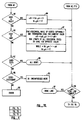
- Figure 7 shows the process for converting MMR to TL, also called decoding MMR. It may be compared with the process described in connection with Figure 4, relating to encoding MMR.
- the process is started (Step AH and the various initial values and pointers are initialized, with the initial color being set to WHITE (Step AI).
- the process then enters a loop.
- the next step is to find, from the input data stream, the next two dimensional code which satisfies one of several criteria: VL3, VL2, VL1, V0, VR1, VR2, VRE3, HOR, PASS, EXTENSION or EOB (Step AJ).
- the codes are then tested.
- Step AK If the code is V0 (Step AK), the a0 value is initialized to a first value, as noted in the flow chart, the b 1 pointer is incremented, and the colors are switched (Step AL) completing the coding phase.
- the code is VL1 through VL3 (Step AM)
- the a 0 value is initialized to a second value, as noted in the flow chart and the colors are switched (Step AN). Thereafter the b1 pointer minus 1 is tested against the initial value a 0 (Step AO) and the b 1 pointer is either decremented (Step AP) or incremented (Step AQ) toward a value related to a 0, as noted in the flow chart. This also completes the coding phase.
- Step AR If the code is VR1 through VR3 (Step AR), the a0 value is initialized to a third value, as noted in the flow chart and the colors are switched (Step AS). Thereafter the bl pointer is tested against the initial value a0 (Step AT) and the bl pointer is either incremented by 2 (Step AU) or considered complete. This also completes the coding phase.
- Step AV If the code is PASS (Step AV), the a0 value is initialized to a fourth value, the bl pointer is incremented by 2 (Step AW), also completing the coding phase.
- Step AX If the code is HOR for horizontal (Step AX), certain codes related to the horizontal coding are invoked. Optionally, the horizontal make-up codes are found, and then the terminating code for the current color is found. Thereafter, the a 0 value is set as noted in Figure 7 for both colors during a loop under which certain conditions are true (Step AY). This completes the horizontal portion of the coding phase.
- Step AZ EOB (End of Block) code
- Step BA the end of the sequence is noted
- Step BA This also completes the coding phase.
- the code is an extension code (EXT) (Step BB)
- Step BC the encoding executed is related to an optional uncompressed mode (Step BC). Absent any other valid code, the result is an error signal (Step BD).
- Step BE the value a o is tested against the total line length (Step BE). If it is less, then the process is repeated from Step AJ. If it matches line length, then the line is done and coding is complete. The process returns the transition line suited to conversions to other coding schemes.
- Appendixes attached hereto provide details on one embodiment of the invention.
- Appendix A illustrates and outlines a procedure for implementing TL to MMR conversion.
- Appendix B provides detailed source code listing of the decoding and encoding processes in accordance with one embodiment of the invention.
Landscapes
- Engineering & Computer Science (AREA)
- Multimedia (AREA)
- Signal Processing (AREA)
- Physics & Mathematics (AREA)
- General Physics & Mathematics (AREA)
- Theoretical Computer Science (AREA)
- Compression, Expansion, Code Conversion, And Decoders (AREA)
- Image Processing (AREA)
Claims (9)
- Verfahren zur Umwandlung eines ersten Bildes, das durch einen ersten graphischen Bildcode beschrieben wird, in ein entsprechendes zweites Bild, das durch einen zweiten graphischen Bildcode beschrieben wird, wobei es dem ersten graphischen Bildcode und dem zweiten graphischen Bildcode an einer 1- zu -1-Entsprechung der Wortumwandlung fehlt und das Verfahren umfaßt:eine Analyse des ersten graphischen Bildcodes, der das erste Bild repräsentiert, um eine erste Abtastzeilendarstellung für jede Abtastzeile des ersten graphischen Bildes zu identifizieren;eine Umwandlung der ersten Abtastzeilendarstellung in eines von mehreren Codesegmenten (86-98) eines Umschaltlistencodes (80), wobei jedes Codesegment eine veränderliche Länge aufweist und aus mehreren Codeworten gebildet wird, wobei jedes Codewort eine feste Länge aufweist und die variable Länge von der Anzahl der Codeworte mit fester Länge in jedem Codesegment abhängt;einer Aufsammlung der Codesegmente, um den Umschaltlistencode aufzubauen;eine Umwandlung des Umschaltlistencodes in den zweiten graphischen Bildcode entsprechend dem zweiten Bild.
- Verfahren nach Anspruch 1, wobei der Umschaltlistencode eine Liste von Umschaltungen zwischen schwarzen und weißen Bildelementen für jede Abtastzeile umfaßt.
- Verfahren nach Anspruch 2, wobei die Umschaltliste eine Liste von Lauflängen von Pixeln (pels) in Codewörtern fester Länge umfaßt.
- Verfahren nach Anspruch 2, wobei jede Umschaltliste ein erstes Umschaltlisten-Codewort besitzt, das die Anzahl der Umschaltungen pro Abtastzeile festlegt.
- Verfahren nach einem der Ansprüche 1 bis 4, umfassend den Schritt der Verarbeitung des Umschaltlistencodes, um den Ursprung des zweiten Bildes vor dem Aufbau des zweiten Bildes zu manipulieren.
- Vorrichtung (10) zur Umwandlung eines ersten graphischen Bildcodes in ein entsprechendes zweites Bild, das durch einen zweiten graphischen Bildcode beschrieben wird, wobei es dem ersten graphischen Bildcode und dem zweiten graphischen Bildcode an einer 1- zu -1-Entsprechung der Codewortumwandlung fehlt und die Vorrichtung (10) umfaßt:Mittel (12, 32) zum Analysieren des ersten graphischen Bildcodes, der das erste Bild repräsentiert, um eine erste Abtastzeilendarstellung für jede Abtastzeile des ersten graphischen Bildcodes zu identifizieren;Mittel (14, 18) zur Umwandlung der ersten Abtastzeilendarstellung in eines von mehreren Codesegmenten (86 - 98) eines Umschaltlistencodes (80), wobei jedes Codesegment eine veränderliche Länge aufweist und aus mehreren Codeworten gebildet wird, wobei jedes Codewort eine feste Länge aufweist und die variable Länge von der Anzahl der Codeworte mit fester Länge in jedem Codesegment abhängt;Mittel (26) zum Speichern der Codesegmente in einer geordneten Weise, um den Umschaltlistencode (80) aufzubauen; undMittel (16, 42) zur Umwandlung des Umschaltlistencodes (80) in den zweiten graphischen Bildcode entsprechend dem zweiten graphischen Bild.
- Vorrichtung nach Anspruch 6, wobei der Umschaltlistencode eine Liste von Umschaltungen zwischen schwarzen und weißen Bildelementen für jede Abtastzeile umfaßt.
- Vorrichtung nach Anspruch 7, wobei jede Umschaltliste ein erstes Umschaltlisten-Codewort besitzt, das die Anzahl der Umschaltungen pro Abtastzeile festlegt.
- Vorrichtung nach einem der Ansprüche 6 bis 8, wobei der Umschaltlistencode verarbeitet wird, um die Quelle des zweiten Bildes zu manipulieren, bevor das zweite Bild aufgebaut wird.
Applications Claiming Priority (3)
| Application Number | Priority Date | Filing Date | Title |
|---|---|---|---|
| US07/261,956 US5095512A (en) | 1988-10-24 | 1988-10-24 | Method and apparatus for manipulating image data employing an intermediate format |
| US261956 | 1988-10-24 | ||
| PCT/US1989/004758 WO1990004838A1 (en) | 1988-10-24 | 1989-10-24 | Method for converting and processing compressed image data in multiple formats |
Publications (3)
| Publication Number | Publication Date |
|---|---|
| EP0441896A1 EP0441896A1 (de) | 1991-08-21 |
| EP0441896A4 EP0441896A4 (en) | 1992-07-22 |
| EP0441896B1 true EP0441896B1 (de) | 1997-05-14 |
Family
ID=22995599
Family Applications (1)
| Application Number | Title | Priority Date | Filing Date |
|---|---|---|---|
| EP90901108A Expired - Lifetime EP0441896B1 (de) | 1988-10-24 | 1989-10-24 | Verfahren zur umwandlung und behandlung verdichteter bilddaten zu mehrfachen formaten |
Country Status (6)
| Country | Link |
|---|---|
| US (1) | US5095512A (de) |
| EP (1) | EP0441896B1 (de) |
| JP (1) | JPH04502992A (de) |
| CA (1) | CA2001405C (de) |
| DE (1) | DE68928046T2 (de) |
| WO (1) | WO1990004838A1 (de) |
Families Citing this family (17)
| Publication number | Priority date | Publication date | Assignee | Title |
|---|---|---|---|---|
| DE69131369T2 (de) * | 1990-07-31 | 1999-12-16 | Canon K.K., Tokio/Tokyo | Gerät und Verfahren zur Bildverarbeitung |
| DE69132625T2 (de) * | 1990-07-31 | 2001-10-31 | Canon K.K., Tokio/Tokyo | Gerät zur Bildverarbeitung |
| JP3066909B2 (ja) * | 1990-08-27 | 2000-07-17 | キヤノン株式会社 | 復号装置 |
| JP3485938B2 (ja) * | 1992-03-31 | 2004-01-13 | 株式会社東芝 | 不揮発性半導体メモリ装置 |
| JP2951572B2 (ja) | 1994-09-12 | 1999-09-20 | インターナショナル・ビジネス・マシーンズ・コーポレイション | 画像データ変換方法及びシステム |
| JP3014031B2 (ja) * | 1995-07-17 | 2000-02-28 | 日本電気株式会社 | 動画圧縮装置 |
| US5726760A (en) * | 1996-04-03 | 1998-03-10 | Oce-Nederland, B.V. | Method and apparatus for converting image representation formats as well as an image production system provided with such an apparatus |
| US5872568A (en) * | 1996-08-14 | 1999-02-16 | International Business Machines Corporation | Application and method for creating a list from pre-defined and user values |
| US5867157A (en) * | 1996-08-14 | 1999-02-02 | International Business Machines Corporation | Graphical interface method, apparatus and application for creating and modifying a list of values with multiple components |
| US5818444A (en) * | 1996-08-14 | 1998-10-06 | International Business Machines Corporation | Method, apparatus and application for object selective but global attribute modification |
| US6195096B1 (en) | 1996-08-14 | 2001-02-27 | International Business Machines Corporation | Graphical interface method, apparatus and application for creating and modifying a multiple-value text list |
| US5781193A (en) * | 1996-08-14 | 1998-07-14 | International Business Machines Corporation | Graphical interface method, apparatus and application for creating multiple value list from superset list |
| US6104395A (en) * | 1996-08-14 | 2000-08-15 | International Business Machines Corporation | Graphical interface method, apparatus and application for opening window of all designated container objects |
| US5774120A (en) * | 1996-08-14 | 1998-06-30 | International Business Machines Corporation | Refresh and select-all actions in graphical user interface |
| US5774119A (en) * | 1996-08-14 | 1998-06-30 | International Business Machines Corporation | Graphical interface method, apparatus and application for selection of target object |
| US5784057A (en) * | 1996-08-14 | 1998-07-21 | International Business Machines Corporation | Dynamically modifying a graphical user interface window title |
| US7054015B1 (en) | 1999-07-02 | 2006-05-30 | Electronics For Imaging, Inc. | Printer description file format generator |
Family Cites Families (8)
| Publication number | Priority date | Publication date | Assignee | Title |
|---|---|---|---|---|
| US4876607A (en) * | 1982-03-31 | 1989-10-24 | International Business Machines Corporation | Complex character generator utilizing byte scanning |
| GB2139849B (en) * | 1983-05-07 | 1986-11-19 | Nippon Telegraph & Telephone | Image data compression system |
| US4610027A (en) * | 1983-12-30 | 1986-09-02 | International Business Machines Corporation | Method for converting a bit map of an image to a run length or run end representation |
| JPH0783427B2 (ja) * | 1984-04-03 | 1995-09-06 | キヤノン株式会社 | 画像伝送方法 |
| US4646356A (en) * | 1984-06-29 | 1987-02-24 | International Business Machines Corporation | Method for converting a bit map of an image to a run length or run end representation |
| US4821336A (en) * | 1987-02-19 | 1989-04-11 | Gtx Corporation | Method and apparatus for simplifying runlength data from scanning of images |
| US4783834A (en) * | 1987-02-20 | 1988-11-08 | International Business Machines Corporation | System for creating transposed image data from a run end or run length representation of an image |
| US4858017A (en) * | 1988-01-22 | 1989-08-15 | The Trustees Of Columbia University In The City Of New York | System and method for hierarchal image encoding and decoding |
-
1988
- 1988-10-24 US US07/261,956 patent/US5095512A/en not_active Expired - Lifetime
-
1989
- 1989-10-24 DE DE68928046T patent/DE68928046T2/de not_active Expired - Fee Related
- 1989-10-24 WO PCT/US1989/004758 patent/WO1990004838A1/en not_active Ceased
- 1989-10-24 EP EP90901108A patent/EP0441896B1/de not_active Expired - Lifetime
- 1989-10-24 JP JP2501183A patent/JPH04502992A/ja not_active Expired - Lifetime
- 1989-10-24 CA CA002001405A patent/CA2001405C/en not_active Expired - Lifetime
Also Published As
| Publication number | Publication date |
|---|---|
| CA2001405A1 (en) | 1990-04-24 |
| US5095512A (en) | 1992-03-10 |
| CA2001405C (en) | 1999-03-23 |
| WO1990004838A1 (en) | 1990-05-03 |
| JPH04502992A (ja) | 1992-05-28 |
| EP0441896A4 (en) | 1992-07-22 |
| DE68928046D1 (de) | 1997-06-19 |
| DE68928046T2 (de) | 1997-08-28 |
| EP0441896A1 (de) | 1991-08-21 |
Similar Documents
| Publication | Publication Date | Title |
|---|---|---|
| CA2001405C (en) | Method for converting and processing compressed image data in multiple formats | |
| EP0680016B1 (de) | System und Verfahren zur Bildkompression | |
| US5838333A (en) | Image processing device and image processing method | |
| EP0188678B1 (de) | Drehungsverfahren und -gerät für binäre Bilder | |
| US6985630B2 (en) | Image processing apparatus and method, program and storage medium | |
| US4829385A (en) | Data communication apparatus | |
| JP3453407B2 (ja) | 画像処理装置、画像出力装置、画像出力システム、およびその方法 | |
| CA1286766C (en) | Method and apparatus for decompressing encoded data | |
| US5608862A (en) | Apparatus for processing hierarchically-coded image data | |
| US5867612A (en) | Method and apparatus for the fast scaling of an image | |
| US6011566A (en) | System and method to display raster images with negligible delay time and reduced memory requirements | |
| EP0703549A2 (de) | Zweidimensionales Verfahren und System zur Binärbilddatenkompression | |
| US20010043747A1 (en) | Signal processing equipment | |
| EP0597698B1 (de) | Bildverarbeitungsgerät und Verfahren zur Bildverarbeitung | |
| McIntyre et al. | File format for internet fax | |
| Ageenko et al. | Enhanced JBIG-based compression for satisfying objectives of engineering document management system | |
| JP3082930B2 (ja) | 画像処理装置 | |
| EP0820186B1 (de) | Signalprozessor | |
| US20020101606A1 (en) | Fast preview of CCITT-compressed documents | |
| JP3736107B2 (ja) | 画像処理装置 | |
| KR900007566B1 (ko) | 화상데이터 변환장치 및 방법 | |
| JP3092194B2 (ja) | 画像合成装置 | |
| EP0652670A1 (de) | Bildkodierungsgerät und -verfahren | |
| JPH0254675A (ja) | 情報ファイル装置 | |
| JPH0410868A (ja) | データ通信装置 |
Legal Events
| Date | Code | Title | Description |
|---|---|---|---|
| PUAI | Public reference made under article 153(3) epc to a published international application that has entered the european phase |
Free format text: ORIGINAL CODE: 0009012 |
|
| 17P | Request for examination filed |
Effective date: 19910423 |
|
| AK | Designated contracting states |
Kind code of ref document: A1 Designated state(s): DE FR GB |
|
| A4 | Supplementary search report drawn up and despatched |
Effective date: 19920604 |
|
| AK | Designated contracting states |
Kind code of ref document: A4 Designated state(s): DE FR GB |
|
| 17Q | First examination report despatched |
Effective date: 19940407 |
|
| GRAG | Despatch of communication of intention to grant |
Free format text: ORIGINAL CODE: EPIDOS AGRA |
|
| GRAG | Despatch of communication of intention to grant |
Free format text: ORIGINAL CODE: EPIDOS AGRA |
|
| GRAH | Despatch of communication of intention to grant a patent |
Free format text: ORIGINAL CODE: EPIDOS IGRA |
|
| GRAH | Despatch of communication of intention to grant a patent |
Free format text: ORIGINAL CODE: EPIDOS IGRA |
|
| GRAA | (expected) grant |
Free format text: ORIGINAL CODE: 0009210 |
|
| AK | Designated contracting states |
Kind code of ref document: B1 Designated state(s): DE FR GB |
|
| REF | Corresponds to: |
Ref document number: 68928046 Country of ref document: DE Date of ref document: 19970619 |
|
| ET | Fr: translation filed | ||
| PLBE | No opposition filed within time limit |
Free format text: ORIGINAL CODE: 0009261 |
|
| STAA | Information on the status of an ep patent application or granted ep patent |
Free format text: STATUS: NO OPPOSITION FILED WITHIN TIME LIMIT |
|
| 26N | No opposition filed | ||
| REG | Reference to a national code |
Ref country code: GB Ref legal event code: IF02 |
|
| PGFP | Annual fee paid to national office [announced via postgrant information from national office to epo] |
Ref country code: DE Payment date: 20071018 Year of fee payment: 19 |
|
| PGFP | Annual fee paid to national office [announced via postgrant information from national office to epo] |
Ref country code: FR Payment date: 20071009 Year of fee payment: 19 Ref country code: GB Payment date: 20071024 Year of fee payment: 19 |
|
| GBPC | Gb: european patent ceased through non-payment of renewal fee |
Effective date: 20081024 |
|
| REG | Reference to a national code |
Ref country code: FR Ref legal event code: ST Effective date: 20090630 |
|
| PG25 | Lapsed in a contracting state [announced via postgrant information from national office to epo] |
Ref country code: DE Free format text: LAPSE BECAUSE OF NON-PAYMENT OF DUE FEES Effective date: 20090501 |
|
| PG25 | Lapsed in a contracting state [announced via postgrant information from national office to epo] |
Ref country code: FR Free format text: LAPSE BECAUSE OF NON-PAYMENT OF DUE FEES Effective date: 20081031 |
|
| PG25 | Lapsed in a contracting state [announced via postgrant information from national office to epo] |
Ref country code: GB Free format text: LAPSE BECAUSE OF NON-PAYMENT OF DUE FEES Effective date: 20081024 |