EP0441912B1 - Procede et appareil destines a un systeme de remplacement de particules en circulation dans un courant permettant le contact a contre-courant d'un courant d'alimentation en gaz et en liquide avec un lit tasse - Google Patents
Procede et appareil destines a un systeme de remplacement de particules en circulation dans un courant permettant le contact a contre-courant d'un courant d'alimentation en gaz et en liquide avec un lit tasse Download PDFInfo
- Publication number
- EP0441912B1 EP0441912B1 EP90911055A EP90911055A EP0441912B1 EP 0441912 B1 EP0441912 B1 EP 0441912B1 EP 90911055 A EP90911055 A EP 90911055A EP 90911055 A EP90911055 A EP 90911055A EP 0441912 B1 EP0441912 B1 EP 0441912B1
- Authority
- EP
- European Patent Office
- Prior art keywords
- catalyst
- bed
- flow
- vessel
- reactor vessel
- Prior art date
- Legal status (The legal status is an assumption and is not a legal conclusion. Google has not performed a legal analysis and makes no representation as to the accuracy of the status listed.)
- Expired - Lifetime
Links
- 239000007788 liquid Substances 0.000 title claims abstract description 94
- 239000002245 particle Substances 0.000 title claims description 84
- 238000000034 method Methods 0.000 title claims description 43
- 239000003054 catalyst Substances 0.000 claims abstract description 317
- 229930195733 hydrocarbon Natural products 0.000 claims abstract description 57
- 150000002430 hydrocarbons Chemical class 0.000 claims abstract description 57
- 239000004215 Carbon black (E152) Substances 0.000 claims abstract description 55
- 238000000926 separation method Methods 0.000 claims abstract description 6
- 239000012530 fluid Substances 0.000 claims description 61
- 239000000203 mixture Substances 0.000 claims description 20
- 238000010791 quenching Methods 0.000 claims description 15
- 230000004323 axial length Effects 0.000 claims description 13
- 230000000630 rising effect Effects 0.000 claims description 7
- 238000005339 levitation Methods 0.000 claims description 6
- 230000004048 modification Effects 0.000 claims description 3
- 238000012986 modification Methods 0.000 claims description 3
- 230000000737 periodic effect Effects 0.000 claims description 3
- 238000011084 recovery Methods 0.000 claims description 3
- 239000006185 dispersion Substances 0.000 claims description 2
- 238000011010 flushing procedure Methods 0.000 claims description 2
- 238000012423 maintenance Methods 0.000 claims description 2
- 230000000903 blocking effect Effects 0.000 claims 2
- 238000011144 upstream manufacturing Methods 0.000 abstract 1
- 239000007789 gas Substances 0.000 description 81
- UFHFLCQGNIYNRP-UHFFFAOYSA-N Hydrogen Chemical compound [H][H] UFHFLCQGNIYNRP-UHFFFAOYSA-N 0.000 description 57
- 239000001257 hydrogen Substances 0.000 description 48
- 229910052739 hydrogen Inorganic materials 0.000 description 48
- 238000012546 transfer Methods 0.000 description 35
- 230000008569 process Effects 0.000 description 16
- 239000002002 slurry Substances 0.000 description 13
- 239000003921 oil Substances 0.000 description 12
- 238000013461 design Methods 0.000 description 11
- 238000009826 distribution Methods 0.000 description 11
- IJGRMHOSHXDMSA-UHFFFAOYSA-N Atomic nitrogen Chemical compound N#N IJGRMHOSHXDMSA-UHFFFAOYSA-N 0.000 description 10
- 230000005484 gravity Effects 0.000 description 10
- 238000006243 chemical reaction Methods 0.000 description 8
- 230000005251 gamma ray Effects 0.000 description 8
- 229910052751 metal Inorganic materials 0.000 description 8
- 239000002184 metal Substances 0.000 description 7
- 238000002156 mixing Methods 0.000 description 7
- 230000008901 benefit Effects 0.000 description 6
- 238000012545 processing Methods 0.000 description 6
- 150000002739 metals Chemical class 0.000 description 5
- 238000012360 testing method Methods 0.000 description 5
- PXHVJJICTQNCMI-UHFFFAOYSA-N Nickel Chemical compound [Ni] PXHVJJICTQNCMI-UHFFFAOYSA-N 0.000 description 4
- 238000005299 abrasion Methods 0.000 description 4
- 229910052757 nitrogen Inorganic materials 0.000 description 4
- 238000005204 segregation Methods 0.000 description 4
- 230000003197 catalytic effect Effects 0.000 description 3
- 239000010779 crude oil Substances 0.000 description 3
- 150000002431 hydrogen Chemical class 0.000 description 3
- 239000007791 liquid phase Substances 0.000 description 3
- 239000012071 phase Substances 0.000 description 3
- 239000007787 solid Substances 0.000 description 3
- XLYOFNOQVPJJNP-UHFFFAOYSA-N water Substances O XLYOFNOQVPJJNP-UHFFFAOYSA-N 0.000 description 3
- 241000899793 Hypsophrys nicaraguensis Species 0.000 description 2
- CPLXHLVBOLITMK-UHFFFAOYSA-N Magnesium oxide Chemical compound [Mg]=O CPLXHLVBOLITMK-UHFFFAOYSA-N 0.000 description 2
- ZOKXTWBITQBERF-UHFFFAOYSA-N Molybdenum Chemical compound [Mo] ZOKXTWBITQBERF-UHFFFAOYSA-N 0.000 description 2
- VYPSYNLAJGMNEJ-UHFFFAOYSA-N Silicium dioxide Chemical compound O=[Si]=O VYPSYNLAJGMNEJ-UHFFFAOYSA-N 0.000 description 2
- NINIDFKCEFEMDL-UHFFFAOYSA-N Sulfur Chemical compound [S] NINIDFKCEFEMDL-UHFFFAOYSA-N 0.000 description 2
- 238000010521 absorption reaction Methods 0.000 description 2
- 238000013019 agitation Methods 0.000 description 2
- 239000003245 coal Substances 0.000 description 2
- 229910017052 cobalt Inorganic materials 0.000 description 2
- 239000010941 cobalt Substances 0.000 description 2
- GUTLYIVDDKVIGB-UHFFFAOYSA-N cobalt atom Chemical compound [Co] GUTLYIVDDKVIGB-UHFFFAOYSA-N 0.000 description 2
- 238000004939 coking Methods 0.000 description 2
- 150000001875 compounds Chemical class 0.000 description 2
- 239000000356 contaminant Substances 0.000 description 2
- 230000001276 controlling effect Effects 0.000 description 2
- 230000007423 decrease Effects 0.000 description 2
- 238000006477 desulfuration reaction Methods 0.000 description 2
- 230000023556 desulfurization Effects 0.000 description 2
- 229910001873 dinitrogen Inorganic materials 0.000 description 2
- 230000000694 effects Effects 0.000 description 2
- 238000005243 fluidization Methods 0.000 description 2
- 238000002347 injection Methods 0.000 description 2
- 239000007924 injection Substances 0.000 description 2
- 238000002955 isolation Methods 0.000 description 2
- 238000005259 measurement Methods 0.000 description 2
- 229910052750 molybdenum Inorganic materials 0.000 description 2
- 239000011733 molybdenum Substances 0.000 description 2
- 229910052759 nickel Inorganic materials 0.000 description 2
- 230000002093 peripheral effect Effects 0.000 description 2
- BASFCYQUMIYNBI-UHFFFAOYSA-N platinum Chemical compound [Pt] BASFCYQUMIYNBI-UHFFFAOYSA-N 0.000 description 2
- 230000008929 regeneration Effects 0.000 description 2
- 238000011069 regeneration method Methods 0.000 description 2
- 230000001105 regulatory effect Effects 0.000 description 2
- 230000002441 reversible effect Effects 0.000 description 2
- 239000003079 shale oil Substances 0.000 description 2
- 238000003860 storage Methods 0.000 description 2
- 229910052717 sulfur Inorganic materials 0.000 description 2
- 239000011593 sulfur Substances 0.000 description 2
- WFKWXMTUELFFGS-UHFFFAOYSA-N tungsten Chemical compound [W] WFKWXMTUELFFGS-UHFFFAOYSA-N 0.000 description 2
- 229910052721 tungsten Inorganic materials 0.000 description 2
- 239000010937 tungsten Substances 0.000 description 2
- 238000009827 uniform distribution Methods 0.000 description 2
- 229910001347 Stellite Inorganic materials 0.000 description 1
- RTAQQCXQSZGOHL-UHFFFAOYSA-N Titanium Chemical compound [Ti] RTAQQCXQSZGOHL-UHFFFAOYSA-N 0.000 description 1
- PNEYBMLMFCGWSK-UHFFFAOYSA-N aluminium oxide Inorganic materials [O-2].[O-2].[O-2].[Al+3].[Al+3] PNEYBMLMFCGWSK-UHFFFAOYSA-N 0.000 description 1
- 230000003466 anti-cipated effect Effects 0.000 description 1
- 239000010426 asphalt Substances 0.000 description 1
- 230000003190 augmentative effect Effects 0.000 description 1
- 230000015572 biosynthetic process Effects 0.000 description 1
- 238000006555 catalytic reaction Methods 0.000 description 1
- TVFDJXOCXUVLDH-RNFDNDRNSA-N cesium-137 Chemical compound [137Cs] TVFDJXOCXUVLDH-RNFDNDRNSA-N 0.000 description 1
- AHICWQREWHDHHF-UHFFFAOYSA-N chromium;cobalt;iron;manganese;methane;molybdenum;nickel;silicon;tungsten Chemical compound C.[Si].[Cr].[Mn].[Fe].[Co].[Ni].[Mo].[W] AHICWQREWHDHHF-UHFFFAOYSA-N 0.000 description 1
- 239000000571 coke Substances 0.000 description 1
- 238000010276 construction Methods 0.000 description 1
- 230000008602 contraction Effects 0.000 description 1
- 238000005336 cracking Methods 0.000 description 1
- 238000007324 demetalation reaction Methods 0.000 description 1
- 230000006866 deterioration Effects 0.000 description 1
- 239000003344 environmental pollutant Substances 0.000 description 1
- 230000007717 exclusion Effects 0.000 description 1
- 238000007572 expansion measurement Methods 0.000 description 1
- 235000003642 hunger Nutrition 0.000 description 1
- 230000006872 improvement Effects 0.000 description 1
- 238000009434 installation Methods 0.000 description 1
- 239000000395 magnesium oxide Substances 0.000 description 1
- 239000000463 material Substances 0.000 description 1
- 238000005272 metallurgy Methods 0.000 description 1
- 150000002902 organometallic compounds Chemical class 0.000 description 1
- 238000012856 packing Methods 0.000 description 1
- 239000003208 petroleum Substances 0.000 description 1
- 229910052697 platinum Inorganic materials 0.000 description 1
- 231100000719 pollutant Toxicity 0.000 description 1
- 230000002285 radioactive effect Effects 0.000 description 1
- 239000000376 reactant Substances 0.000 description 1
- 239000012495 reaction gas Substances 0.000 description 1
- 238000004064 recycling Methods 0.000 description 1
- 230000008439 repair process Effects 0.000 description 1
- 238000012163 sequencing technique Methods 0.000 description 1
- 230000035939 shock Effects 0.000 description 1
- 238000004904 shortening Methods 0.000 description 1
- 239000000377 silicon dioxide Substances 0.000 description 1
- 239000002594 sorbent Substances 0.000 description 1
- 230000037351 starvation Effects 0.000 description 1
- 239000011269 tar Substances 0.000 description 1
- 239000011275 tar sand Substances 0.000 description 1
- 229910052719 titanium Inorganic materials 0.000 description 1
- 239000010936 titanium Substances 0.000 description 1
- 239000010913 used oil Substances 0.000 description 1
- 230000008016 vaporization Effects 0.000 description 1
- 239000002699 waste material Substances 0.000 description 1
- 238000009736 wetting Methods 0.000 description 1
Images


Classifications
-
- B—PERFORMING OPERATIONS; TRANSPORTING
- B01—PHYSICAL OR CHEMICAL PROCESSES OR APPARATUS IN GENERAL
- B01J—CHEMICAL OR PHYSICAL PROCESSES, e.g. CATALYSIS OR COLLOID CHEMISTRY; THEIR RELEVANT APPARATUS
- B01J8/00—Chemical or physical processes in general, conducted in the presence of fluids and solid particles; Apparatus for such processes
- B01J8/08—Chemical or physical processes in general, conducted in the presence of fluids and solid particles; Apparatus for such processes with moving particles
- B01J8/12—Chemical or physical processes in general, conducted in the presence of fluids and solid particles; Apparatus for such processes with moving particles moved by gravity in a downward flow
- B01J8/125—Chemical or physical processes in general, conducted in the presence of fluids and solid particles; Apparatus for such processes with moving particles moved by gravity in a downward flow with multiple sections one above the other separated by distribution aids, e.g. reaction and regeneration sections
-
- B—PERFORMING OPERATIONS; TRANSPORTING
- B01—PHYSICAL OR CHEMICAL PROCESSES OR APPARATUS IN GENERAL
- B01J—CHEMICAL OR PHYSICAL PROCESSES, e.g. CATALYSIS OR COLLOID CHEMISTRY; THEIR RELEVANT APPARATUS
- B01J8/00—Chemical or physical processes in general, conducted in the presence of fluids and solid particles; Apparatus for such processes
- B01J8/008—Details of the reactor or of the particulate material; Processes to increase or to retard the rate of reaction
-
- B—PERFORMING OPERATIONS; TRANSPORTING
- B01—PHYSICAL OR CHEMICAL PROCESSES OR APPARATUS IN GENERAL
- B01J—CHEMICAL OR PHYSICAL PROCESSES, e.g. CATALYSIS OR COLLOID CHEMISTRY; THEIR RELEVANT APPARATUS
- B01J8/00—Chemical or physical processes in general, conducted in the presence of fluids and solid particles; Apparatus for such processes
- B01J8/18—Chemical or physical processes in general, conducted in the presence of fluids and solid particles; Apparatus for such processes with fluidised particles
- B01J8/1881—Chemical or physical processes in general, conducted in the presence of fluids and solid particles; Apparatus for such processes with fluidised particles with particles moving downwards while fluidised
-
- B—PERFORMING OPERATIONS; TRANSPORTING
- B01—PHYSICAL OR CHEMICAL PROCESSES OR APPARATUS IN GENERAL
- B01J—CHEMICAL OR PHYSICAL PROCESSES, e.g. CATALYSIS OR COLLOID CHEMISTRY; THEIR RELEVANT APPARATUS
- B01J8/00—Chemical or physical processes in general, conducted in the presence of fluids and solid particles; Apparatus for such processes
- B01J8/18—Chemical or physical processes in general, conducted in the presence of fluids and solid particles; Apparatus for such processes with fluidised particles
- B01J8/20—Chemical or physical processes in general, conducted in the presence of fluids and solid particles; Apparatus for such processes with fluidised particles with liquid as a fluidising medium
- B01J8/22—Chemical or physical processes in general, conducted in the presence of fluids and solid particles; Apparatus for such processes with fluidised particles with liquid as a fluidising medium gas being introduced into the liquid
-
- C—CHEMISTRY; METALLURGY
- C10—PETROLEUM, GAS OR COKE INDUSTRIES; TECHNICAL GASES CONTAINING CARBON MONOXIDE; FUELS; LUBRICANTS; PEAT
- C10G—CRACKING HYDROCARBON OILS; PRODUCTION OF LIQUID HYDROCARBON MIXTURES, e.g. BY DESTRUCTIVE HYDROGENATION, OLIGOMERISATION, POLYMERISATION; RECOVERY OF HYDROCARBON OILS FROM OIL-SHALE, OIL-SAND, OR GASES; REFINING MIXTURES MAINLY CONSISTING OF HYDROCARBONS; REFORMING OF NAPHTHA; MINERAL WAXES
- C10G49/00—Treatment of hydrocarbon oils, in the presence of hydrogen or hydrogen-generating compounds, not provided for in a single one of groups C10G45/02, C10G45/32, C10G45/44, C10G45/58 or C10G47/00
- C10G49/002—Apparatus for fixed bed hydrotreatment processes
-
- C—CHEMISTRY; METALLURGY
- C10—PETROLEUM, GAS OR COKE INDUSTRIES; TECHNICAL GASES CONTAINING CARBON MONOXIDE; FUELS; LUBRICANTS; PEAT
- C10G—CRACKING HYDROCARBON OILS; PRODUCTION OF LIQUID HYDROCARBON MIXTURES, e.g. BY DESTRUCTIVE HYDROGENATION, OLIGOMERISATION, POLYMERISATION; RECOVERY OF HYDROCARBON OILS FROM OIL-SHALE, OIL-SAND, OR GASES; REFINING MIXTURES MAINLY CONSISTING OF HYDROCARBONS; REFORMING OF NAPHTHA; MINERAL WAXES
- C10G49/00—Treatment of hydrocarbon oils, in the presence of hydrogen or hydrogen-generating compounds, not provided for in a single one of groups C10G45/02, C10G45/32, C10G45/44, C10G45/58 or C10G47/00
- C10G49/10—Treatment of hydrocarbon oils, in the presence of hydrogen or hydrogen-generating compounds, not provided for in a single one of groups C10G45/02, C10G45/32, C10G45/44, C10G45/58 or C10G47/00 with moving solid particles
- C10G49/14—Treatment of hydrocarbon oils, in the presence of hydrogen or hydrogen-generating compounds, not provided for in a single one of groups C10G45/02, C10G45/32, C10G45/44, C10G45/58 or C10G47/00 with moving solid particles according to the "moving-bed" technique
-
- B—PERFORMING OPERATIONS; TRANSPORTING
- B01—PHYSICAL OR CHEMICAL PROCESSES OR APPARATUS IN GENERAL
- B01J—CHEMICAL OR PHYSICAL PROCESSES, e.g. CATALYSIS OR COLLOID CHEMISTRY; THEIR RELEVANT APPARATUS
- B01J2208/00—Processes carried out in the presence of solid particles; Reactors therefor
- B01J2208/00796—Details of the reactor or of the particulate material
- B01J2208/00884—Means for supporting the bed of particles, e.g. grids, bars, perforated plates
Definitions
- the present invention relates to on-stream catalyst replacement during hydroprocessing of a hydrocarbon feed stream.
- Catalysts are selected by measuring bed expansion in a large pilot plant run with hydrocarbon, hydrogen and catalysts at the design pressures and flow velocities within the available reaction volume of the vessel. Catalyst is removed from the bed by laminar flow of the catalyst particles in a liquid slurry system in which the liquid flow line is uniform in diameter, and substantially larger than the catalyst particles, throughout the flow path between the reactor vessel and a pressurizable vessel, including passageways through the flow control valves.
- hydroprocessing catalyst for such a reactor which typically contains metals such as titanium, cobalt, nickel, tungsten, molybdenum, etc., may involve a catalyst inventory of 226,800 kg (500,000 pounds) and a cost $2 to $4 per 0.454 kg (pound). Accordingly, for economic feasibility in commercial operations, the process must handle high flow rates and the vessel should be filled with as much catalyst as possible to maximize catalyst activity and run length. Additionally, the down-time for replacement or renewal of catalyst must be as short as possible.
- the economics of the process will generally depend upon the versatility of the system to handle feed strears of varying amounts of contaminants such as sulfur, nitrogen, metals and/or organic-metallic compounds, such as those found in a wide variety of the more plentiful (and hence cheaper) crude oils, residua, or liquified coal, tar sand bitumen or shale oils, as well as used oils, and the like.
- contaminants such as sulfur, nitrogen, metals and/or organic-metallic compounds, such as those found in a wide variety of the more plentiful (and hence cheaper) crude oils, residua, or liquified coal, tar sand bitumen or shale oils, as well as used oils, and the like.
- a counterflow reactor vessel comprising: a reservoir formed in the lower end of said reactor vessel wherein a fluid mixture of a hydrocarbon liquid and a reactive gas are mixed for simultaneous flow upwardly through a bed of particles extending upwardly through said reactor vessel; means for adding said particles at least periodically at the upper end of said vessel; means for removing said particles from the lower end of said bed after counterflow downwardly through said upwardly flowing stream of said fluid mixture; and a pervious conical support means for supporting said bed of particles and through which said fluid mixture enters the lower end of said bed from said reservoir at the lower end of said reactor vessel; characterised in that said particle bed support means comprises a truncated conical screen member that extends across substantially the full diameter of said reactor vessel and that has a conical portion that is uniformly pervious for fluid flow therethrough and that has a truncated central apex portion, in that the lower pervious conical surface of said screen member abuts a plurality of concentric annular baffle members supported by
- the bed level of catalyst within the vessel is continuously measured, as by gamma ray absorption, to assure that little ebulation of the bed is occurring.
- Such control is further promoted by evenly distributing both the hydrogen and liquid feed throughout the length of the bed by concentrically distributing both the hydrogen gas component and the hydrocarbon fluid feed component in alternate, concentric annular paths across the full horizontal cross-sectional area of the vessel as they both enter the catalyst bed.
- hydrogen is evenly redistributed and if needed, augmented, through a quench system at one or more intermediate levels along the length of the catalyst bed. Equalizing hydrogen and liquid feed across the full horizontal area along the length of the packed particle bed prevents local turbulence and undesirable vertical segregation of lighter particles from heavier particles flowing in a plug-like manner downwardly through the vessel.
- the annular flow paths are through a conical or pyramidal screen, or perforated plate, which supports the bed or column of catalyst across the vessel through a plurality of radially spaced apart and axially elongated concentric rings, or polygons, supported by radial arms extending from the center of the vessel to the cylindrical side wall of the vessel.
- Each ring is formed by a pair of peripheral members extending between the radial arms directly under the conical screen so that this forms a circular gas pocket at the upper level in each ring so that between each pair of said peripheral members alternate rings of gas and hydrocarbon liquid enter the bed simultaneously.
- U.S. Patent 4,312,741 Jacquin. et al . is directed toward a method of on-stream catalyst replacement in a hydroprocessing system by controlling the feed of hydrogen gas at one or more levels.
- Catalyst as an ebulated bed counterflows through the reactor but is slowed at each of several levels by horizontally constricted areas which increase the hydrogen and hydrocarbon flow rates to sufficiently locally slow downward flow of catalyst. While local recycling thus occurs at each such stage, rapid through-flow of fresh catalyst, with resultant mixing with deactivated or contaminated catalyst, is suppressed.
- the ebulating bed aids simple gravity withdrawal of catalyst from the vessel. Improvement of the disclosed system over multiple vessels with valves between stages is suggested to avoid the risk of rapid wear and deterioration of valve seals by catalyst abrasion.
- U.S. Patent 3,716,478, Kodera. et al . discloses low linear velocity of a mixed feed of liquid and H2 gas to avoid expansion (or contraction) of catalyst bed.
- gas bubbles are controlled by flow through the packed bed, but the bed is fluidized by forming the bottom with a small cross-sectional area adjacent the withdrawal tube. This assists discharge of catalyst without back-mixing of contaminated catalyst with fresh catalyst at the top of the single vessel.
- the range of the bed level in the vessel is from 0.9 to 1.1 of the allowable bed volume ( ⁇ 10%) due to fluid flow through the bed.
- U.S. Patent 4,571,326, Bischoff. et al. is directed to apparatus for withdrawing catalyst through the center of a catalyst bed counterflowing to a liquid hydrocarbon and gas feed stream.
- the system is particularly directed to arrangements for assuring uniform distribution of hydrogen gas with the liquid feed across the cross-sectional area of the bed. Such uniform distribution appears to be created because the bed is ebulating under the disclosed conditions of flow. Accordingly, considerable reactor space is used to initially mix the gas and hydrocarbon liquid feeds in the lower end of the vessel before flowing to other bottom feed distributors.
- the feeds are further mixed at a higher level by such distributor means in the form of "Sulzer Plates” or a “honeycomb” of hexagonal tubes beneath a truncated, conical, or pyramidal-shaped funnel screen.
- the arrangement may include an open ramp area parallel to the underside of the screen between the tube or plate ends.
- quench gas is supplied through upflowing jets in star-shaped or annular headers extending across middle portions of the vessel.
- the arrangement for withdrawal of spent catalyst requires ebulation of at least the lower portion of the bed.
- U.S. Patent 4,259,294, Van ZijllLanahaut. et al . is directed to a system for on-stream catalyst replacement by entrainment of the catalyst in oil pumped as a slurry either to withdraw catalyst from or to supply fresh catalyst to, a reactor vessel.
- Reacting feed is suggested to be either co-current or countercurrent with catalyst flow through the reactor.
- Valves capable of closing with catalyst in the line, or after back-flow of slurry oil, are required to seal off the catalyst containing vessel at operating temperatures and pressures from the receiving reactor vessel, or isolate the catalyst receiving lock hopper from the withdrawal section of the vessel.
- U.S. Patents 3,470,900, Carson , and 4,167,474, Sikama respectively illustrate multiple single bed reactors and multi-bed reactors in which catalyst is replaced either continuously or periodically.
- the feed and catalyst flow co-currently and/or radially.
- Catalyst is regenerated and returned to the reactor, or disposed of.
- No catalyst withdrawal system is disclosed apart from either the configuration of the internal bed support or the shape of the vessel bottom to assist gravity discharge of catalyst.
- a method of periodically or semi-continuously transferring catalyst into and out of a substantially packed bed of catalyst flowing downwardly at a desired rate through a reactor vessel during hydroprocessing over a wide range of counterflow rates of a hydrocarbon feed stream and a hydrogen containing gas flowing upwardly through the vessel Such plug-like flow of the packed catalyst bed is achieved by selecting the average density, size, and shape of the catalyst particles forming the bed so that the bed expands by less than 10% at the maximum anticipated fluid flow velocities of the gaseous and liquid components therethrough. Desirably such movement and bed level of such catalyst is continuously monitored to prevent overfilling and to assure minimum ebulation and attendant wastage of reactor space and particle size segregation.
- the invention relates to methods and apparatus for on-stream replacement of catalyst without local levitation or ebulation of catalyst particles around the withdrawal point within the catalyst bed by laminarly flowing a liquid hydrocarbon stream either into, or out of, the reactor vessel through a pair of flow paths.
- Each of the flow paths has a substantially constant cross-sectional area throughout its length and a diameter at least five times the average diameter of the catalyst particles flowing between said vessel and at least one and preferably two, pressurizable catalyst lock-hoppers or receptacles, serving respectively to supply fresh catalyst to the top of the bed and to remove spent catalyst from the bottom.
- a hydroprocessing system is shown embodying the method of the present invention to increase substantially both the continued catalytic activity of a volume or bed of catalyst 10 and the efficient use of a single reactor vessel of a given volume, such as reactor vessel 11.
- Vessel 11 as indicated by the thickness of its cylindrical side wall 12 and domed closure heads, or ends, 13 and 14, is designed to react a hydrogen containing gas mixed with a liquid hydrocarbon stream at a pressure of up to about 30400 kN/m2 (300 atmospheres (about 4500 lbs per square inch)) and up to about 650° C (about 1200° F).
- Such reaction gas and a feed stream of hydrocarbon liquids are preferably premixed and introduced as a single stream through bottom head 13 by line 16.
- the upper level of bed 10, designated as 20, is preferably controlled on a continuous basis by gamma ray absorption measurement made possible by a gamma ray source 22 and gamma ray detector 24 positioned at the top 20 of bed 10.
- a gamma ray source may be in the form of radioactive isotopes, such as Cesium 137, disposed inside the reactor.
- the source can be an electrically controllable source,such as a thermal neutron activated gamma ray generator.
- Detector 24 may be in the form of an ionization tube, Geiger-Mueller tube or a scintillation detector. Suitable sources and detectors are manufactured by Ronan Engineering Co.
- bed support means 17 is particularly characterized by the truncated polygonal or conical configuration of support means 17.
- the vertical or axial length of plates 27 which set off each individual annular and radial segment provide equal access to both hydrogen and liquid feed into catalyst bed 10, and that the plates 27 are so stepped under screen 28 so that they effectively form rings of gas and hydrocarbon feed alternately across the full diameter at the inlet side of bed 10. In this way, no single area of the inlet to bed 10 becomes a segregated or preferential, flow path for either gas or the liquid. Further, if pressure surges result in full wetting of screen 28 by the liquid phase, recovery of gas flow is assisted by the areal breadth of each segment between plates 27 and radial plates 26.
- a particular advantage to using tubes, as compared to a combination of tubes and perforations, is that the designed flow distribution pattern is maintained over a wider range of flow rates.
- gas normally flows up the perforations and liquid flows up the tubes.
- gas will find new flow paths through the tubes if the gas flow increases or the perforations become plugged, resulting in undesigned and potentially undesirable flow patterns.
- the location of one of the gas redistribution stages 39 is illustrated by the single inverted angle member 40 extending transverse to the axis of bed 10.
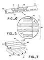
- the details of quench system 39 are best seen in Figures 5 to 7 where a plurality of inverted v-shaped sheds 40 are equally distributed over at least one transverse row extending generally across the cross-sectional area of vessel 11.
- a gas injection line 42 feeds an elongated tube 41 extending through each individual shed 40 from a header 44 and branch lines 45 supplying the individual tubes 41.
- a second tier of sheds 40 is axially spaced above the first tier, with the sheds in each tier being positioned at 90° to the other tier, as shown in Figure 5.
- Construction of an individual shed 40 is best seen in Figure 6, wherein distribution pipe 41 includes a plurality of discharge holes 48, desirably proportioned to give equal distribution of hydrogen gas along the full length of tube 41.
- Figure 1 shows a catalyst replacement system, which in general comprises a series of lock chambers for transferring fresh catalyst into bed 10 through a pair of pressure lock chambers, including charging hopper 60 and supply hopper 70.
- the pressure differential between vessel 11 and hoppers 60 or 80 be accurately controlled as by detecting the pressure differences between supply line 61 or discharge line 82 and vessel 11.
- the pressure difference is best zero when shut-off valves 64 or 84 are first opened or closed.
- the pressure differences between vessel 11 and line 61 is measured by gage 63 and pressure detectors 62 and 65.
- Differential pressure gage 83 and detectors 81 and 85 serve a similar function to control transfer of catalyst through valve 84 from the bottom of vessel 11 to discharge hopper 80.
- vessels 70 and 60 are at atmospheric pressure, catalyst is first introduced into a storage hopper 70 by way of funnel 100 through line 101 and valve 102, and nitrogen is preferably flushed through vessel 70 through line 104 and/or line 71 to eliminate air and moisture that may be present on the catalyst.
- vessel 70 is charged with a hydrocarbon refined stream, preferably vacuum gas oil, to provide the necessary slurrying liquid for mixing and transporting catalyst. This may either be through funnel 100, valve 102, and line 101, or through line 104, valve 105 and line 106. Valve 102 is then closed.
- valve 75 to assure that all such catalyst is through valve 75, (so that the valve need not close on hard, abrasive catalyst with potential danger of scoring the valve or the valve seat) additional flush fluid is preferably introduced from line 77 through valve 78 to clear line 76, either back into vessel 70, or forward into vessel 60.
- valve 64 should be opened for transfer.
- the actual laminar transfer of the liquid slurry is controlled by valve 67 throttling the flow and pressure of hydrogen admitted from line 66.
- valve 68 in flush line 69 is opened briefly to assure that any catalyst left in lines 61 and 19 is cleared before valve 64 is closed, for the reasons noted before. Excess hydrogen pressure in vessel 60 may be relieved by any suitable bleed line running back to the common hydrogen source of the hydroprocessing system. (not shown)
- vessel 11 is controlled in the same way to discharge hopper or lock vessel 80.
- the flow path from inlet 30 of J-tube 29, through line 82, including the bore of valve 84 is uniform in cross-sectional area and diameter.
- transfer from discharge hopper 80 to disposal vessel 90 is through inlet 89 of J-tube 86 to discharge outlet 98 of line 92, including valve 94, into vessel 90.
- each of the transfer valves in the present arrangement are preferably conventional ball valves formed with a single through bore in a rotatable ball. Specifically, we have found that conventional valves used to feed and control flow of hydrocarbons, catalyst and hydrogen, into and out of the vessel 11, must seal against high pressure differentials between the vessel and the transfer hoppers.
- Figure 4 illustrates a partial view of the bottom of pyramidal catalyst bed support 17 showing an alternate system for transferring catalyst in a laminarly flowing liquid.
- an L-valve is formed by vertical tube 54 and horizontal tube 52 for withdrawing catalyst particles from the volume of bed 10.
- intake 56 is preferably directly above the central, non-perforated, section 25 of the truncated pyramid formed by screen support means 17. While such an arrangement is less preferred than that shown in the embodiment of Figure 1, such an arrangement is made suitable by the fact that the slurry of liquid and catalyst can be made to flow only under laminar flow conditions.
- valve 84 After valve 84 has been flushed with vacuum gas oil through valve 88 and line 87 and then closed, the residuum is drained from vessel 80 through drain line 120, below J-tube 86 and conical screen 121. Flush oil is then sent in through valve 93 to wash residuum off the catalyst and to cool the catalyst. The vessel can be drained and filled as many times as needed.
- the pressure in vessel 80 is then reduced to a lower pressure (about 50 psig or less).
- the pressure in vessel 90 is made equal to that in vessel 80 and valve 94 is opened.
- the flow and pressure are then controlled through valve 110 to induce laminar flow of catalyst through J-tube 86 and into vessel 90.
- Valve 94 is flushed with flush oil through valve 107 and closed.
- Table II is a similar set of runs using beds of three of the same catalyst particles as those tested under conditions shown in Table I except that the liquid viscosity, liquid density and pressure of the hydrocarbon feed stream and gas were lower in Table II than Table I to match a different set of commercial operating conditions. From Tables I and II the effect of catalyst particle size, density and shape are clearly indicated for different flow conditions for the liquid and gas components of the feed.
- the design feed rates for a hydrocarbon treating process were calculated by standard scaling procedures to indicate the values in MBPD (thousands of barrels per day) through a reactor vessel containing a catalyst bed 3.5 m (11.5 feet) in diameter.
Landscapes
- Chemical & Material Sciences (AREA)
- Organic Chemistry (AREA)
- Chemical Kinetics & Catalysis (AREA)
- Engineering & Computer Science (AREA)
- Oil, Petroleum & Natural Gas (AREA)
- Combustion & Propulsion (AREA)
- General Chemical & Material Sciences (AREA)
- Devices And Processes Conducted In The Presence Of Fluids And Solid Particles (AREA)
- Production Of Liquid Hydrocarbon Mixture For Refining Petroleum (AREA)
Claims (16)
- Cuve de réacteur à contre-courant (11) comprenant:
un réservoir formé à l'extrémité inférieure de ladite cuve de réacteur (11), dans lequel un mélange fluide d'un liquide d'hydrocarbure et d'un gaz réactif sont mélangés en vue d'un écoulement simultané vers le haut à travers un lit (10) de particules s'étendant vers le haut à travers ladite cuve de réacteur (11);
des moyens destinés à ajouter lesdites particules au moins périodiquement à l'extrémité supérieure de ladite cuve (11);
des moyens destinés à soustraire lesdites particules depuis l'extrémité inférieure dudit lit (10) après être passées à contre-courant à travers le courant s'écoulant vers le haut dudit mélange fluide; et
des moyens à support conique perméable (17) destinés à supporter ledit lit (10) de particules et à travers lesquels ledit mélange fluide entre dans l'extrémité inférieure dudit lit (10) à partir dudit réservoir, à l'extrémité inférieure de ladite cuve de réacteur (11);
caractérisé en ce que lesdits moyens à support de lit particulaire (17) comprennent un élément à écran conique tronqué (28) qui s'étend sensiblement à travers la totalité du diamètre de ladite cuve de réacteur (11) et en ce qu'ils possèdent une partie conique qui est uniformément perméable à l'écoulement fluide passant à travers et en ce qu'ils possèdent une partie à sommet centrale tronquée (25);
en ce que la surface conique perméable inférieure dudit élément à écran (28) aboute contre une pluralité d'éléments à chicanes annulaires concentriques (27) supportés par l'extrémité inférieure de ladite cuve de réacteur (11), lesdits éléments à chicanes (27) formant une pluralité de passages sensiblement annulaires circonférentiels continus concentriques autour, et s'étendant radialement vers l'extérieur, depuis ladite partie centrale tronquée imperméable (25) desdits moyens à support de lit (17), lesdits passages annulaires concentriques procurant un trajet d'écoulement direct à travers le diamètre de ladite cuve de réacteur (11) pour un mélange fluide s'écoulant depuis ledit réservoir formé entre l'extrémité inférieure de ladite cuve de réacteur (11) et la partie inférieure desdits moyens à support de lit (17), à l'exception du passage à travers ladite partie centrale imperméable (25) desdits moyens à support de lit (17);
en ce que ledit réservoir comprend en outre des moyens à paroi généralement horizontaux (31) s'étendant à travers ladite cuve de réacteur (11) à un niveau compris entre la paroi d'extrémité inférieure de ladite cuve de réacteur (11) et lesdits moyens à support de lit catalytique (17), afin de diviser le volume dudit réservoir en une chambre d'équilibre inférieure (35) destinée à recevoir ledit mélange de gaz et de liquide entrant dans ladite cuve de réacteur (11) et une chambre de tranquillisation supérieure séparée (33), lesdits moyens à paroi (31) comprenant une pluralité de tubes (32) sensiblement écartés de façon équidistante les uns des autres et s'étendant radialement autour desdits moyens à paroi (31) au-dessous dudit élément à écran (28) desdits moyens à support de lit (17), lesdits tubes (32) s'étendant vers le bas depuis lesdits moyens à paroi (31) dans ladite chambre d'équilibre (35) à une profondeur telle qu'est assuré uniquement un écoulement d'alimentation mélangé, comprenant les composants gazeux de ce mélange, entrant dans ladite chambre de tranquillisation (33) à travers lesdits moyens à paroi (31);
en ce que lesdits éléments à chicanes (27) sont radialement écartés les uns des autres d'une distance qui empêche une séparation excessive des composants gazeux et liquides dudit mélange fluide avant de former plusieurs moyens d'alimentation fluide annulaires concentriques séparés sous ladite partie conique dudit élément à écran (28), chacun desdits moyens d'alimentation fluide annulaires étant formé par des paires adjacentes desdits éléments à chicanes (27) s'étendant axialement vers le bas dans ladite chambre de tranquillisation (33) depuis ledit élément à écran conique perméable (28) à une profondeur suffisante pour former lesdits canaux annulaires séparés de gaz et de liquide adjacents à l'aboutement des extrémités supérieures desdits éléments à chicanes (27) et à la surface inférieure de ladite partie conique perméable dudit élément à écran (28);
et en ce que le bord inférieur de chacun desdits éléments à chicanes (27) possède une longueur axiale intermédiaire sur la longueur axiale de chaque élément à chicanes concentrique adjacent (27), de sorte que ledit fluide mélangé est simultanément alimenté en bandes concentriques alternées de gaz et de liquide entre chaque paire d'éléments à chicanes (27), dans la totalité du diamètre et de la circonférence desdits moyens à support de lit (17), à l'exception du passage à travers ladite partie imperméable tronquée (25) desdits moyens à support de lit (17). - Cuve de réacteur (11) selon la revendication 1, dans laquelle:
lesdits moyens destinés à ajouter des particules audit lit (10) à l'extrémité supérieure de ladite cuve de réacteur (11) comprennent au moins une ligne d'écoulement (19) s'étendant dans ladite cuve de réacteur (11) à un niveau situé au-dessus de l'extrémité supérieure (20) dudit lit (10);
lesdits moyens destinés à soustraire des particules depuis l'extrémité inférieure de ladite cuve de réacteur (11) comprennent une autre ligne d'écoulement (29) comportant une sortie à un niveau directement adjacent et audessus de ladite partie centrale imperméable tronquée (25) dudit support de lit (17);
chacune desdites lignes d'écoulement (19, 29) possède un diamètre sensiblement uniforme s'étendant sur sa longueur depuis ladite cuve de réacteur (11) à au moins une cuve sous pression externe (60, 80) chacune desdites lignes d'écoulement (19, 29) comprenant au moins un robinet à boisseau sphérique (64, 84) comportant un orifice continu qui n'est pas plus petit que sa ligne d'écoulement respective, chacune desdites lignes d'écoulement (19, 29) étant directement connectée respectivement à ladite au moins une cuve sous pression externe (60, 80) afin d'alimenter en particules neuves la partie supérieure dudit lit (10) et afin de recevoir les particules usées soustraites depuis la partie inférieure dudit lit (10); et
des moyens sont prévus pour contrôler indépendamment les pressions desdites cuves sous pression (60, 80) afin de réguler le débit de fluide à travers lesdites lignes d'écoulement (19, 29) afin de provoquer un écoulement laminaire de liquide à travers lesdites lignes d'écoulement (19, 29) pour induire l'écoulement laminaire du liquide à travers lesdites lignes d'écoulement en vue de transporter les particules dans et en dehors de ladite cuve de réacteur (11) sans modifier l'écoulement des composants dudit mélange fluide dans ladite cuve de réacteur (11) sur la longueur axiale dudit lit (10). - Cuve de réacteur (11) selon la revendication 1 ou 2, dans laquelle lesdits moyens à support de lit (17) comprennent une pluralité d'éléments à chicanes radiaux écartés circonférentiellement (26) s'étendant radialement vers l'intérieur à partir du périmètre externe dudit élément à écran (28) vers ladite partie centrale imperméable (25) dudit élément à écran (28) afin de supporter ladite pluralité d'éléments à chicanes concentriques (27) contre la surface inférieure dudit élément à écran conique (28).
- Cuve de réacteur (11) selon la revendication 1, 2 ou 3, dans laquelle lesdits moyens à support de lit (17) ont une forme de pyramide polygonale tronquée et dans laquelle chacun desdits éléments à chicanes généralement cylindriques (27) comprend une pluralité de segments, chaque segment étant parallèle à un des côtés de ladite pyramide polygonale et ses extrémités en aboutement correspondant aux coins d'intersection sur les côtés adjacents du polygone formant lesdits éléments à chicanes concentriques (27).
- Cuve de réacteur (11) selon l'une quelconque des revendications 1 à 4, dans laquelle ladite ligne d'écoulement (29) comprend un tube en forme de J s'étendant à travers et au-dessus desdits moyens à écran de support de lit conique tronqué (17) afin de disposer l'entrée (30) dudit tube en forme de J vers le bas et directement au-dessus de ladite partie centrale imperméable (25) desdits moyens à support de lit catalytique (17).
- Cuve de réacteur (11) selon l'une quelconque des revendications 1 à 5, dans laquelle ladite entrée (30) dudit tube en forme de J est généralement perpendiculaire à et adjacent à la surface supérieure de ladite partie centrale imperméable (25) desdits moyens à support de lit catalytique (17).
- Cuve de réacteur (11) selon l'une quelconque des revendications 2 à 6, dans laquelle lesdits moyens de contrôle de pression comprennent des moyens destinés à modifier la pression de ladite cuve sous pression externe (60, 80) afin de commencer et d'arrêter l'écoulement de fluide entre ladite cuve de réacteur (11) et ladite cuve sous pression externe (60, 80) lorsque ledit orifice dudit robinet à boisseau sphérique (64, 84) est ouvert.
- Cuve de réacteur (11) selon l'une quelconque des revendications 1 à 7, dans laquelle ladite ligne d'écoulement (29) comprend au moins des moyens à conduite supplémentaires (87) qui lui sont connectés afin d'introduire un fluide auxiliaire dans ladite ligne d'écoulement (29) entre ladite cuve de reacteur (11) et ledit robinet à boisseau sphérique (84).
- Cuve de réacteur (11) selon la revendication 8, dans laquelle lesdits moyens à conduite supplémentaires (87) comprennent des moyens à vanne auxiliaire (88) afin de contrôler indépendamment l'écoulement de fluide depuis une source externe en vue de dégager sélectivement les particules catalytiques dudit orifice dudit robinet à boisseau sphérique (84) avant sa fermeture, ou afin de permettre le maintien d'un courant de retour de fluide dans ladite cuve (80) à travers ladite entrée de ladite ligne d'écoulement (29) entre des extractions périodiques de catalyseur entraîné dans le fluide extrait de ladite cuve de réacteur (11) à travers ladite ligne d'écoulement (29).
- Cuve de réacteur (11) selon l'une quelconque des revendications 1 à 9, dans laquelle ladite cuve de réacteur (11) comprend des moyens (39) destinés à modifier l'écoulement de gaz à travers ledit lit (10) intermédiaire entre lesdits moyens à support de lit particulaire (17) et la partie supérieure dudit lit (10), lesdits moyens (39) comprenant:
des moyens à versant (40) supportés par ladite cuve de réacteur (11) compris sur sa longueur axiale et s'étendant transversalement à l'axe du lit particulaire (10) qui y est formé, lesdits moyens à versant (40) ayant au moins un moyen à canal de gaz en forme de V renversé s'étendant latéralement à travers ledit lit (10) de façon à dévier latéralement et vers l'extérieur les particules s'écoulant vers le bas au-dessus de la surface supérieure desdits moyens à canal de gaz en forme de V et de façon à dévier le gaz s'écoulant vers le haut sous la surface inférieure desdits moyens à canal en vue de sa dispersion latérale;
des moyens destinés à introduire sélectivement un écoulement de gaz supplémentaire depuis une source externe dans ledit lit particulaire (10), lesdits moyens comprenant des moyens à tubes (42) s'étendant entre ladite source externe et une sortie sous ladite surface inférieure desdits moyens à canal de gaz en forme de V, lesdits moyens à canal de gaz en forme de V étant imperméables à l'écoulement de gaz à travers une partie majeure desdites surfaces supérieure et inférieure. - Cuve de réacteur (11) selon la revendication 10, dans laquelle lesdits moyens à versant (40) comprennent une pluralité de fentes allongées (50) s'étendant le long et à travers les bords inférieurs desdits moyens à canal de gaz en forme de V afin de distribuer le gaz depuis ces derniers dans ledit lit particulaire (10).
- Procédé de remplacement de catalyseur en circulation destiné à fournir périodiquement ou continûment du catalyseur neuf à une cuve de réacteur (11) ayant un courant d'alimentation s'écoulant vers le haut comprenant un composant gazeux et un composant liquide s'élevant à travers un lit tassé sensiblement descendant (10) dudit catalyseur s'étendant axialement à travers ladite cuve de réacteur (11), le procédé comprenant:
la sélection de la taille, de la forme et de la densité des particules dudit catalyseur formant le lit catalytique tassé (10) en fonction du débit d'écoulement et de la viscosité dudit courant d'alimentation durant le contact avec ledit catalyseur afin d'éviter sensiblement l'ébullition et/ou la lévitation au-dessus d'une partie substantielle de la longueur axiale dudit lit tassé (10) à un débit choisi dudit courant d'alimentation;
la distribution uniforme du composant gazeux dudit courant d'alimentation à la base dudit lit catalytique (10) et à travers l'aire de la section transversale de ce dernier de façon à éviter une ébullition localisé dudit lit (10) le long de sa longueur axiale, y compris la recirculation des particules catalytiques dans ce dernier, lorsque ledit catalyseur se déplace vers le bas en écoulement de retour à travers ladite cuve (11), ledit courant d'alimentation étant introduit dans ladite base dudit lit (10) à travers une pluralité de zones annulaires concentriques sous une surface conique ou pyramidale perméable (17) s'étendant radialement vers l'extérieur depuis une zone centrale imperméable tronquée (25) supportant ledit lit catalytique (10) lesdites zones annulaires concentriques formant des trajets d'alimentation vers le haut alternés uniformément concentriques desdits composants liquide et gazeux au-dessus de ladite aire de la section transversale perméable;
le maintien additionnel dudit écoulement de retour dudit lit catalytique vers le bas à travers ladite cuve de réacteur (11);
la soustraction périodique des particules catalytiques depuis une partie centrale de ladite base dudit lit (10) en faisant s'écouler une partie du composant liquide dudit courant d'alimentation depuis ladite cuve de réacteur (11) ledit écoulement liquide ayant un débit qui ne dépasse pas le seuil de l'écoulement laminaire et s'effectuant directement depuis le dessus de ladite partie imperméable tronquée (25) dudit support conique ; et
le remplacement périodique des particules catalytiques dudit lit (10) en entraînant les particules catalytiques dans un courant liquide sous pression afin de créer un écoulement laminaire dudit courant dans l'extrémité supérieure de ladite cuve de réacteur (11). - Procédé selon la revendication 12, comprenant en outre l'injection de gaz de refroidissement et l'interception des composants gazeux s'écoulant vers le haut dans ledit lit (10) à travers au moins un niveau intermédiaire sur la longueur dudit lit (10) afin de refroidir et de détourner latéralement l'écoulement de gaz à travers une pluralité de trajets d'écoulement s'étendant transversalement, chacun desdits trajets d'écoulement transversaux s'effectuant sous un versant en forme de V renversé (40) positionné pour dévier vers le bas les particules catalytiques s'écoutant vers l'extérieur au-dessus de la surface transversale dudit versant (40), chacun desdits versants (40) comprenant une pluralité de fentes allongées (50) formant des trajets d'écoulement écartés longitudinalement le long des bords externes desdites surfaces transversales afin de distribuer le gaz vers le haut à travers ces fentes.
- Procédé selon la revendication 12 ou 13, dans lequel lesdites particules catalytiques sont éliminées vers une cuve de récupération (80), dans lequel l'écoulement laminaire est maintenu sur un trajet d'écoulement à aire transversale uniforme entre ladite cuve de réacteur (11) et ladite cuve de récupération (80) et dans lequel ledit trajet d'écoulement comprend au moins un robinet à boisseau sphérique à orifice total (84) monté en ligne et destiné à transporter les particules catalytiques entraînées dans ledit courant d'écoulement liquide.
- Procédé selon la revendication 14, comprenant en outre le blocage sélectif des particules catalytiques à l'entrée dudit trajet d'écoulement en faisant s'écouler à contre-courant le fluide depuis une source auxiliaire dans ledit trajet d'écoulement primaire afin d'empêcher le blocage de ladite entrée entre les extractions de catalyseur dudit lit (10).
- Procédé selon l'une quelconque des revendications 12 à 15, dans lequel lesdites particules catalytiques sont remplacées depuis une cuve sous pression (60), et dans lequel ledit courant liquide s'écoule à travers un trajet d'écoulement ayant une aire de section transversale sensiblement uniforme sur toute sa longueur et un diamètre au moins égal à cinq fois le diamètre moyen des particules catalytiques s'écoulant à travers, ledit trajet d'écoulement laminaire comprenant en outre au moins un robinet à boisseau sphérique à orifice total (64) monté en ligne et de diamètre sensiblement identique à celui dudit trajet d'écoulement afin de maintenir le passage dudit écoulement laminaire à travers ce robinet, et présentant au moins un trajet d'écoulement fluide auxiliaire destiné à introduire sélectivement un fluide auxiliaire dans ledit trajet d'écoulement à un niveau intermédiaire vers ladite cuve sous pression (60) et à l'entrée de ladite cuve de réacteur (11) afin de chasser les particules catalytiques dudit trajet, y compris l'orifice total dudit robinet à boisseau sphérique (64) monté en ligne.
Applications Claiming Priority (3)
| Application Number | Priority Date | Filing Date | Title |
|---|---|---|---|
| US07/381,948 US5076908A (en) | 1989-07-19 | 1989-07-19 | Method and apparatus for an on-stream particle replacement system for countercurrent contact of a gas and liquid feed stream with a packed bed |
| US381948 | 1989-07-19 | ||
| PCT/US1990/004007 WO1991001359A1 (fr) | 1989-07-19 | 1990-07-17 | Procede et appareil destines a un systeme de remplacement de particules en circulation dans un courant permettant le contact a contre-courant d'un courant d'alimentation en gaz et en liquide avec un lit tasse |
Publications (3)
| Publication Number | Publication Date |
|---|---|
| EP0441912A1 EP0441912A1 (fr) | 1991-08-21 |
| EP0441912A4 EP0441912A4 (en) | 1992-01-15 |
| EP0441912B1 true EP0441912B1 (fr) | 1995-02-15 |
Family
ID=23506972
Family Applications (1)
| Application Number | Title | Priority Date | Filing Date |
|---|---|---|---|
| EP90911055A Expired - Lifetime EP0441912B1 (fr) | 1989-07-19 | 1990-07-17 | Procede et appareil destines a un systeme de remplacement de particules en circulation dans un courant permettant le contact a contre-courant d'un courant d'alimentation en gaz et en liquide avec un lit tasse |
Country Status (11)
| Country | Link |
|---|---|
| US (3) | US5076908A (fr) |
| EP (1) | EP0441912B1 (fr) |
| JP (1) | JPH07119425B2 (fr) |
| CN (1) | CN1028111C (fr) |
| AT (1) | ATE118526T1 (fr) |
| CA (1) | CA1332496C (fr) |
| DE (1) | DE69017000T2 (fr) |
| DK (1) | DK0441912T3 (fr) |
| ES (1) | ES2069083T3 (fr) |
| MY (1) | MY105733A (fr) |
| WO (1) | WO1991001359A1 (fr) |
Families Citing this family (76)
| Publication number | Priority date | Publication date | Assignee | Title |
|---|---|---|---|---|
| US5916529A (en) * | 1989-07-19 | 1999-06-29 | Chevron U.S.A. Inc | Multistage moving-bed hydroprocessing reactor with separate catalyst addition and withdrawal systems for each stage, and method for hydroprocessing a hydrocarbon feed stream |
| US5498327A (en) * | 1989-07-19 | 1996-03-12 | Stangeland; Bruce E. | Catalyst, method and apparatus for an on-stream particle replacement system for countercurrent contact of a gas and liquid feed stream with a packed bed |
| US5589057A (en) * | 1989-07-19 | 1996-12-31 | Chevron U.S.A. Inc. | Method for extending the life of hydroprocessing catalyst |
| US5472928A (en) * | 1989-07-19 | 1995-12-05 | Scheuerman; Georgieanna L. | Catalyst, method and apparatus for an on-stream particle replacement system for countercurrent contact of a gas and liquid feed stream with a packed bed |
| US5492617A (en) * | 1989-07-19 | 1996-02-20 | Trimble; Harold J. | Apparatus and method for quenching in hydroprocessing of a hydrocarbon feed stream |
| ATE128724T1 (de) * | 1990-07-17 | 1995-10-15 | Chevron Usa Inc | Kohlenwasserstoffbehandlung eines gas enthaltenden zulaufes in einem gegenstromkatalysatorfliessbett. |
| FR2678944B1 (fr) * | 1991-07-10 | 1993-11-19 | Total Raffinage Distribution Sa | Procede et dispositif pour le remplacement en continu du catalyseur dans une unite a lit mobile. |
| EP0553931B1 (fr) * | 1992-01-30 | 1997-04-16 | Shell Internationale Researchmaatschappij B.V. | Procédé d'amélioration d'une charge hydrocarbonée |
| US5603904A (en) * | 1993-06-18 | 1997-02-18 | Chevron U.S.A. Inc. | Apparatus for catalyst replacement |
| JP3431216B2 (ja) * | 1993-06-18 | 2003-07-28 | 千代田化工建設株式会社 | 触媒層支持構造 |
| CN1134527C (zh) * | 1994-04-29 | 2004-01-14 | 切夫里昂美国公司 | 催化剂,用于连续颗粒置换体系的方法及设备 |
| EP0766597B1 (fr) * | 1994-06-17 | 2002-08-14 | Chevron U.S.A. Inc. | Support de catalyseur et son procede d'utilisation |
| US5858311A (en) * | 1996-03-14 | 1999-01-12 | Chevron U.S.A. Inc. | Thermocouple well assembly with a sealing coupling and a method for eliminating leaks in hydroconversion reactors while continuing to hydroprocess |
| US5885534A (en) * | 1996-03-18 | 1999-03-23 | Chevron U.S.A. Inc. | Gas pocket distributor for hydroprocessing a hydrocarbon feed stream |
| US5879642A (en) * | 1996-04-24 | 1999-03-09 | Chevron U.S.A. Inc. | Fixed bed reactor assembly having a guard catalyst bed |
| US6086749A (en) * | 1996-12-23 | 2000-07-11 | Chevron U.S.A. Inc. | Catalyst and method for hydroprocessing a hydrocarbon feed stream in a reactor containing two or more catalysts |
| US5904907A (en) * | 1997-11-03 | 1999-05-18 | Chevron U.S.A., Inc. | Mixing system for mixing and distributing fluids in a reactor |
| US6387334B1 (en) | 1997-12-30 | 2002-05-14 | Chevron U.S.A. Inc. | Balanced flow resistance OCR distributor cone |
| US6554994B1 (en) | 1999-04-13 | 2003-04-29 | Chevron U.S.A. Inc. | Upflow reactor system with layered catalyst bed for hydrotreating heavy feedstocks |
| CA2388337C (fr) | 1999-10-22 | 2013-01-08 | Aventis Pasteur Limited | Procede visant a provoquer et/ou stimuler une reponse immunitaire aux antigenes tumoraux |
| WO2001044408A1 (fr) * | 1999-12-16 | 2001-06-21 | Chevron U.S.A. Inc. | Cuvees de remplacement d'hydrotraitement de presulfuration d'un catalyseur |
| WO2002030864A1 (fr) * | 2000-10-13 | 2002-04-18 | Mitsubishi Chemical Corporation | Procede de production de diacetoxybutene |
| US7074740B2 (en) * | 2002-07-02 | 2006-07-11 | Chevron U.S.A. Inc. | Catalyst for conversion processes |
| US20040009108A1 (en) * | 2002-07-09 | 2004-01-15 | Meier Paul F. | Enhanced fluid/solids contacting in a fluidization reactor |
| US7807110B2 (en) | 2004-03-12 | 2010-10-05 | Cormetech Inc. | Catalyst systems |
| US7776786B2 (en) | 2004-05-04 | 2010-08-17 | Cormetech, Inc. | Catalyst systems advantageous for high particulate matter environments |
| US7638039B2 (en) * | 2004-06-15 | 2009-12-29 | Cormetech, Inc. | In-situ catalyst replacement |
| FR2877589B1 (fr) | 2004-11-09 | 2007-01-12 | Inst Francais Du Petrole | Reacteur a plusieurs zones en lit fixe ou mobile avec echangeur thermique integre |
| DE102005012942B4 (de) * | 2005-03-21 | 2018-12-13 | Robert Bosch Gmbh | Verfahren und Vorrichtung zum Betreiben einer Brennkraftmaschine |
| US7763767B2 (en) * | 2005-05-04 | 2010-07-27 | Exxonmobil Chemicals Patents Inc. | Adsorption process with on-line adsorbent removal |
| US7638673B2 (en) * | 2005-05-04 | 2009-12-29 | Exxonmobil Chemical Patents Inc. | Process for hydrocarbon conversion with on-line solid particulate material removal |
| US20070012305A1 (en) * | 2005-07-18 | 2007-01-18 | Williams Russell K | Toy Water Rocket Launcher |
| US7658898B2 (en) * | 2006-08-01 | 2010-02-09 | Cormetech, Inc. | Compositions and methods for treating exhaust gases |
| FR2917306B1 (fr) * | 2007-06-12 | 2011-04-15 | Inst Francais Du Petrole | Enceinte contenant un lit granulaire et une distribution d'une phase gazeuse et d'une phase liquide circulant en un ecoulement ascendant dans cette enceinte |
| WO2009073436A2 (fr) * | 2007-11-28 | 2009-06-11 | Saudi Arabian Oil Company | Processus d'hydrotraitement catalytique des pétroles bruts sulfureux |
| US7906081B2 (en) * | 2008-05-13 | 2011-03-15 | Uop Llc | Internal grids for adsorbent chambers and reactors |
| US7901640B2 (en) * | 2008-05-13 | 2011-03-08 | Uop Llc | Optimized counter-current flow baffle |
| US7718146B2 (en) * | 2008-05-13 | 2010-05-18 | Uop Llc | Enhanced bed separation in a styrene monomer reactor using milled plates |
| US20100018904A1 (en) * | 2008-07-14 | 2010-01-28 | Saudi Arabian Oil Company | Prerefining Process for the Hydrodesulfurization of Heavy Sour Crude Oils to Produce Sweeter Lighter Crudes Using Moving Catalyst System |
| WO2010009077A2 (fr) * | 2008-07-14 | 2010-01-21 | Saudi Arabian Oil Company | Processus de traitement d'huiles lourdes au moyen de composants hydrocarbures légers utilisés comme diluent |
| US8372267B2 (en) * | 2008-07-14 | 2013-02-12 | Saudi Arabian Oil Company | Process for the sequential hydroconversion and hydrodesulfurization of whole crude oil |
| US7878736B2 (en) * | 2008-10-30 | 2011-02-01 | Uop Llc | Apparatus for transferring particles |
| US7841807B2 (en) * | 2008-10-30 | 2010-11-30 | Uop Llc | Method of transferring particles |
| US20100152516A1 (en) * | 2008-12-11 | 2010-06-17 | Christopher Naunheimer | Moving Bed Hydrocarbon Conversion Process |
| US7887264B2 (en) * | 2008-12-11 | 2011-02-15 | Uop Llc | Apparatus for transferring particles |
| US7874769B2 (en) * | 2008-12-11 | 2011-01-25 | Uop Llc | Method for transferring particles |
| US7878737B2 (en) * | 2008-12-22 | 2011-02-01 | Uop Llc | Apparatus for transferring particles |
| US7841808B2 (en) * | 2009-01-28 | 2010-11-30 | Uop Llc | Method for transferring particles |
| US20100187159A1 (en) * | 2009-01-28 | 2010-07-29 | Christopher Naunheimer | Moving Bed Hydrocarbon Conversion Process |
| FR2946547B1 (fr) * | 2009-06-10 | 2012-09-21 | Inst Francais Du Petrole | Systeme de rigidification des plateaux d'une colonne multi-etagee de grand diametre. |
| EP2445997B1 (fr) * | 2009-06-22 | 2021-03-24 | Saudi Arabian Oil Company | Demetallisation et desulfurisation d'un petrole brut por coquage retardé |
| US8323476B2 (en) * | 2009-12-17 | 2012-12-04 | Uop Llc | Solid catalyst liquid phase hydroprocessing using moving bed reactors |
| CN102309948A (zh) * | 2010-07-07 | 2012-01-11 | 中国石油化工股份有限公司 | 一种沸腾床催化剂在线加注方法 |
| CN102309947A (zh) * | 2010-07-07 | 2012-01-11 | 中国石油化工股份有限公司 | 沸腾床催化剂在线加注方法 |
| AU2013295528A1 (en) * | 2012-07-26 | 2015-02-19 | Aqseptence Group, Inc. | Enhanced shape support grid |
| US9636652B2 (en) * | 2013-12-05 | 2017-05-02 | Exxonmobil Research And Engineering Company | Reactor bed vessel and support assembly |
| CN105419844B (zh) * | 2015-12-29 | 2017-05-03 | 北京神雾环境能源科技集团股份有限公司 | 下行床热解反应器 |
| CN105419843B (zh) * | 2015-12-29 | 2017-05-31 | 北京神雾环境能源科技集团股份有限公司 | 移动床催化快速热解反应器 |
| CN107790073A (zh) * | 2017-09-28 | 2018-03-13 | 北京中科诚毅科技发展有限公司 | 一种反应器新型内部结构及其设计方法和用途 |
| KR101971160B1 (ko) * | 2017-10-13 | 2019-04-22 | 한국에너지기술연구원 | 피 건조물의 역흐름 다중 방해판 건조장치 |
| CN108144556A (zh) * | 2018-02-02 | 2018-06-12 | 上海英保能源化工科技有限公司 | 一种沸腾床加氢反应系统以及沸腾床加氢工艺方法 |
| CN108148620B (zh) * | 2018-02-02 | 2023-08-15 | 上海竣铭化工工程设计有限公司 | 沸腾床加氢反应设备及沸腾床加氢方法 |
| CN108130123A (zh) * | 2018-02-02 | 2018-06-08 | 上海英保能源化工科技有限公司 | 沸腾床加氢反应系统及沸腾床加氢方法 |
| CN109224855A (zh) * | 2018-11-26 | 2019-01-18 | 佛山科学技术学院 | 一种有机污染物用具有非热等离子体协同催化处理设备 |
| CN109847655B (zh) * | 2019-03-08 | 2024-01-05 | 中国科学技术大学 | 一种用于原位探测高压气固相催化反应产物的实验装置 |
| US11084991B2 (en) * | 2019-06-25 | 2021-08-10 | Saudi Arabian Oil Company | Two-phase moving bed reactor utilizing hydrogen-enriched feed |
| US10933395B1 (en) * | 2019-08-26 | 2021-03-02 | Uop Llc | Apparatus for catalytic reforming hydrocarbons having flow distributor and process for reforming hydrocarbons |
| CN110665443A (zh) * | 2019-11-16 | 2020-01-10 | 安平县燕赵矿筛网业有限公司 | 一种新型双氧水楔形锥体格栅支撑 |
| CN111054275A (zh) * | 2019-11-28 | 2020-04-24 | 广州维港环保科技有限公司 | 一种催化反应装置及其催化反应系统 |
| CN111921460B (zh) * | 2020-06-19 | 2021-03-16 | 宁波巨化化工科技有限公司 | 一种气相醛加氢反应器 |
| JP7689833B2 (ja) * | 2021-02-19 | 2025-06-09 | 出光興産株式会社 | 触媒システム、これを用いた脱金属脱硫処理方法及び脱金属脱硫処理装置 |
| JP7751397B2 (ja) * | 2021-03-29 | 2025-10-08 | 出光興産株式会社 | 反応装置の運転方法及び反応装置 |
| CN116064124B (zh) * | 2021-10-29 | 2025-01-03 | 中国石油化工股份有限公司 | 煤焦油加氢处理装置及方法 |
| CN117619281B (zh) * | 2024-01-26 | 2024-04-05 | 宝鸡市六维特种材料设备制造有限公司 | 一种反应釜反应装置 |
| CN119056347A (zh) * | 2024-02-29 | 2024-12-03 | 中国石油天然气集团有限公司 | Chdm制备过程中两段加氢过程中的催化剂多床层稳态级配装填方法 |
| CN119746733B (zh) * | 2024-11-22 | 2026-03-13 | 中国平煤神马集团尼龙科技有限公司 | 一种用于己内酰胺制6-氨基己腈的氨解反应器 |
Family Cites Families (18)
| Publication number | Priority date | Publication date | Assignee | Title |
|---|---|---|---|---|
| US2882912A (en) * | 1954-06-25 | 1959-04-21 | Union Oil Co | Solids flow control process and apparatus |
| US3336217A (en) * | 1965-07-15 | 1967-08-15 | Cities Scrvice Res And Dev Com | Particulate solids withdrawal method |
| US3470090A (en) * | 1967-09-25 | 1969-09-30 | Universal Oil Prod Co | Method for operating a non-regenerative fixed bed reforming process |
| US3487695A (en) * | 1968-06-12 | 1970-01-06 | Chevron Res | Gas lift catalyst sampler |
| GB1331935A (en) * | 1969-12-12 | 1973-09-26 | Shell Int Research | Peocess for the catalytic hydroconversion of a residual hydroca rbon oil |
| US3716478A (en) * | 1970-02-10 | 1973-02-13 | Agency Ind Science Techn | Hydrogenation treatment of hydrocarbon oil |
| US3880598A (en) * | 1970-12-10 | 1975-04-29 | Shell Oil Co | Residual oil hydrodesulfurization apparatus |
| US3873441A (en) * | 1973-09-06 | 1975-03-25 | Universal Oil Prod Co | Catalyst transfer method for moving-bed reactors |
| US4167474A (en) * | 1977-06-27 | 1979-09-11 | Uop Inc. | Multiple-stage catalytic reforming with gravity-flowing dissimilar catalyst particles |
| NL191022C (nl) * | 1978-01-20 | 1994-12-16 | Shell Int Research | Inrichting geschikt voor het katalytisch hydrogenerend behandelen van zware koolwaterstofoliën. |
| FR2460990A1 (fr) * | 1979-07-09 | 1981-01-30 | Inst Francais Du Petrole | Procede et appareil de conversion catalytique d'hydrocarbures |
| FR2504821B1 (fr) * | 1981-04-29 | 1986-05-02 | Inst Francais Du Petrole | Procede et dispositif pour soutirer des particules solides et introduire une charge liquide a la partie inferieure d'une zone de contact |
| GB2100616B (en) * | 1981-06-30 | 1984-07-18 | Shell Int Research | Moving catalyst bed reactor |
| FR2520634B1 (fr) * | 1982-02-02 | 1987-02-13 | Inst Francais Du Petrole | Procede et dispositif pour soutirer des particules solides et introduire une charge liquide a la partie inferieure d'une zone de contact |
| FR2529905B1 (fr) * | 1982-07-09 | 1988-04-08 | Inst Francais Du Petrole | Procede et dispositif d'hydrotraitement d'hydrocarbures en phase liquide, en presence d'un catalyseur en lit expanse ou bouillonnant |
| FR2533937B1 (fr) * | 1982-10-04 | 1985-10-11 | Inst Francais Du Petrole | Procede et dispositif d'hydroconversion d'hydrocarbures |
| US4968409A (en) * | 1984-03-21 | 1990-11-06 | Chevron Research Company | Hydrocarbon processing of gas containing feed in a countercurrent moving catalyst bed |
| US4664782A (en) * | 1986-01-09 | 1987-05-12 | Intevep, S.A. | Method for withdrawing particulate solid from a high pressure vessel |
-
1989
- 1989-07-19 US US07/381,948 patent/US5076908A/en not_active Expired - Lifetime
- 1989-09-29 CA CA000615373A patent/CA1332496C/fr not_active Expired - Fee Related
-
1990
- 1990-07-17 WO PCT/US1990/004007 patent/WO1991001359A1/fr not_active Ceased
- 1990-07-17 JP JP2510470A patent/JPH07119425B2/ja not_active Expired - Lifetime
- 1990-07-17 EP EP90911055A patent/EP0441912B1/fr not_active Expired - Lifetime
- 1990-07-17 MY MYPI90001191A patent/MY105733A/en unknown
- 1990-07-17 ES ES90911055T patent/ES2069083T3/es not_active Expired - Lifetime
- 1990-07-17 DE DE69017000T patent/DE69017000T2/de not_active Expired - Fee Related
- 1990-07-17 DK DK90911055.3T patent/DK0441912T3/da active
- 1990-07-17 AT AT90911055T patent/ATE118526T1/de not_active IP Right Cessation
- 1990-08-15 CN CN90106981A patent/CN1028111C/zh not_active Expired - Lifetime
-
1993
- 1993-02-08 US US08/014,847 patent/US5302357A/en not_active Expired - Lifetime
-
1994
- 1994-03-21 US US08/215,254 patent/US5409598A/en not_active Expired - Lifetime
Also Published As
| Publication number | Publication date |
|---|---|
| EP0441912A4 (en) | 1992-01-15 |
| WO1991001359A1 (fr) | 1991-02-07 |
| DE69017000T2 (de) | 1995-07-20 |
| CA1332496C (fr) | 1994-10-18 |
| EP0441912A1 (fr) | 1991-08-21 |
| MY105733A (en) | 1994-11-30 |
| CN1028111C (zh) | 1995-04-05 |
| ATE118526T1 (de) | 1995-03-15 |
| DK0441912T3 (da) | 1995-05-15 |
| US5409598A (en) | 1995-04-25 |
| ES2069083T3 (es) | 1995-05-01 |
| JPH03503296A (ja) | 1991-07-25 |
| JPH07119425B2 (ja) | 1995-12-20 |
| CN1059164A (zh) | 1992-03-04 |
| DE69017000D1 (de) | 1995-03-23 |
| US5302357A (en) | 1994-04-12 |
| US5076908A (en) | 1991-12-31 |
Similar Documents
| Publication | Publication Date | Title |
|---|---|---|
| EP0441912B1 (fr) | Procede et appareil destines a un systeme de remplacement de particules en circulation dans un courant permettant le contact a contre-courant d'un courant d'alimentation en gaz et en liquide avec un lit tasse | |
| US5472928A (en) | Catalyst, method and apparatus for an on-stream particle replacement system for countercurrent contact of a gas and liquid feed stream with a packed bed | |
| US5648051A (en) | Apparatus and method for quenching in hydroprocessing of a hydrocarbon feed stream | |
| US5916529A (en) | Multistage moving-bed hydroprocessing reactor with separate catalyst addition and withdrawal systems for each stage, and method for hydroprocessing a hydrocarbon feed stream | |
| US6086749A (en) | Catalyst and method for hydroprocessing a hydrocarbon feed stream in a reactor containing two or more catalysts | |
| US5733440A (en) | Catalyst, method and apparatus for an on-stream particle replacement system for countercurrent contact of a gas and liquid feed stream with a packed bed | |
| US5589057A (en) | Method for extending the life of hydroprocessing catalyst | |
| US5885534A (en) | Gas pocket distributor for hydroprocessing a hydrocarbon feed stream | |
| US5879642A (en) | Fixed bed reactor assembly having a guard catalyst bed | |
| US3410791A (en) | Method for discharging mixture of particulate solids and fluids from high pressure vessel | |
| US7074740B2 (en) | Catalyst for conversion processes | |
| EP0766597B1 (fr) | Support de catalyseur et son procede d'utilisation | |
| WO1995029970A1 (fr) | Catalyseur, procede et appareil destine a un systeme de remplacement de particules assurant un contact a contre-courant entre une charge et un lit garni | |
| US5603904A (en) | Apparatus for catalyst replacement | |
| US3607730A (en) | Apparatus and method for conversion of hydrocarbons | |
| US2695815A (en) | Method of and apparatus for pneumatic transfer of granular contact material in moving bed hydrocarbon conversion processes | |
| US2978279A (en) | Method and apparatus for transferring contact material | |
| US3639230A (en) | Hydrodesulfurization of heavy petroleum hydrocarbon oil in a fluidized reaction zone | |
| US3925025A (en) | Ring-flanged slip-joint for a reactor system | |
| US3849899A (en) | Regulating fluidized beds | |
| GB757986A (en) | Improvements in or relating to conveyance of granular solids |
Legal Events
| Date | Code | Title | Description |
|---|---|---|---|
| PUAI | Public reference made under article 153(3) epc to a published international application that has entered the european phase |
Free format text: ORIGINAL CODE: 0009012 |
|
| 17P | Request for examination filed |
Effective date: 19910411 |
|
| AK | Designated contracting states |
Kind code of ref document: A1 Designated state(s): AT BE CH DE DK ES FR GB IT LI LU NL SE |
|
| A4 | Supplementary search report drawn up and despatched |
Effective date: 19911128 |
|
| AK | Designated contracting states |
Kind code of ref document: A4 Designated state(s): AT BE CH DE DK ES FR GB IT LI LU NL SE |
|
| 17Q | First examination report despatched |
Effective date: 19921020 |
|
| GRAA | (expected) grant |
Free format text: ORIGINAL CODE: 0009210 |
|
| AK | Designated contracting states |
Kind code of ref document: B1 Designated state(s): AT BE CH DE DK ES FR GB IT LI LU NL SE |
|
| REF | Corresponds to: |
Ref document number: 118526 Country of ref document: AT Date of ref document: 19950315 Kind code of ref document: T |
|
| REF | Corresponds to: |
Ref document number: 69017000 Country of ref document: DE Date of ref document: 19950323 |
|
| RAP2 | Party data changed (patent owner data changed or rights of a patent transferred) |
Owner name: CHEVRON U.S.A. INC. |
|
| REG | Reference to a national code |
Ref country code: CH Ref legal event code: PUE Owner name: CHEVRON U.S.A. INC. |
|
| ET | Fr: translation filed | ||
| REG | Reference to a national code |
Ref country code: ES Ref legal event code: FG2A Ref document number: 2069083 Country of ref document: ES Kind code of ref document: T3 |
|
| ITF | It: translation for a ep patent filed | ||
| REG | Reference to a national code |
Ref country code: DK Ref legal event code: T3 |
|
| PG25 | Lapsed in a contracting state [announced via postgrant information from national office to epo] |
Ref country code: LU Free format text: LAPSE BECAUSE OF NON-PAYMENT OF DUE FEES Effective date: 19950731 |
|
| PGFP | Annual fee paid to national office [announced via postgrant information from national office to epo] |
Ref country code: CH Payment date: 19951024 Year of fee payment: 6 |
|
| PLBE | No opposition filed within time limit |
Free format text: ORIGINAL CODE: 0009261 |
|
| STAA | Information on the status of an ep patent application or granted ep patent |
Free format text: STATUS: NO OPPOSITION FILED WITHIN TIME LIMIT |
|
| 26N | No opposition filed | ||
| PG25 | Lapsed in a contracting state [announced via postgrant information from national office to epo] |
Ref country code: LI Effective date: 19960731 Ref country code: CH Effective date: 19960731 |
|
| REG | Reference to a national code |
Ref country code: CH Ref legal event code: PL |
|
| PGFP | Annual fee paid to national office [announced via postgrant information from national office to epo] |
Ref country code: DK Payment date: 19990614 Year of fee payment: 10 |
|
| PGFP | Annual fee paid to national office [announced via postgrant information from national office to epo] |
Ref country code: DE Payment date: 19990730 Year of fee payment: 10 |
|
| PGFP | Annual fee paid to national office [announced via postgrant information from national office to epo] |
Ref country code: AT Payment date: 20000614 Year of fee payment: 11 Ref country code: GB Payment date: 20000614 Year of fee payment: 11 |
|
| PGFP | Annual fee paid to national office [announced via postgrant information from national office to epo] |
Ref country code: NL Payment date: 20000620 Year of fee payment: 11 |
|
| PGFP | Annual fee paid to national office [announced via postgrant information from national office to epo] |
Ref country code: SE Payment date: 20000706 Year of fee payment: 11 |
|
| PGFP | Annual fee paid to national office [announced via postgrant information from national office to epo] |
Ref country code: FR Payment date: 20000707 Year of fee payment: 11 |
|
| PGFP | Annual fee paid to national office [announced via postgrant information from national office to epo] |
Ref country code: ES Payment date: 20000712 Year of fee payment: 11 |
|
| PG25 | Lapsed in a contracting state [announced via postgrant information from national office to epo] |
Ref country code: DK Free format text: LAPSE BECAUSE OF NON-PAYMENT OF DUE FEES Effective date: 20000717 |
|
| REG | Reference to a national code |
Ref country code: DK Ref legal event code: EBP |
|
| PG25 | Lapsed in a contracting state [announced via postgrant information from national office to epo] |
Ref country code: DE Free format text: LAPSE BECAUSE OF NON-PAYMENT OF DUE FEES Effective date: 20010501 |
|
| PG25 | Lapsed in a contracting state [announced via postgrant information from national office to epo] |
Ref country code: AT Free format text: LAPSE BECAUSE OF NON-PAYMENT OF DUE FEES Effective date: 20010717 Ref country code: GB Free format text: LAPSE BECAUSE OF NON-PAYMENT OF DUE FEES Effective date: 20010717 |
|
| PG25 | Lapsed in a contracting state [announced via postgrant information from national office to epo] |
Ref country code: SE Free format text: LAPSE BECAUSE OF NON-PAYMENT OF DUE FEES Effective date: 20010718 Ref country code: ES Free format text: LAPSE BECAUSE OF NON-PAYMENT OF DUE FEES Effective date: 20010718 |
|
| PG25 | Lapsed in a contracting state [announced via postgrant information from national office to epo] |
Ref country code: NL Free format text: LAPSE BECAUSE OF NON-PAYMENT OF DUE FEES Effective date: 20020201 |
|
| EUG | Se: european patent has lapsed |
Ref document number: 90911055.3 |
|
| GBPC | Gb: european patent ceased through non-payment of renewal fee |
Effective date: 20010717 |
|
| PG25 | Lapsed in a contracting state [announced via postgrant information from national office to epo] |
Ref country code: FR Free format text: LAPSE BECAUSE OF NON-PAYMENT OF DUE FEES Effective date: 20020329 |
|
| NLV4 | Nl: lapsed or anulled due to non-payment of the annual fee |
Effective date: 20020201 |
|
| REG | Reference to a national code |
Ref country code: FR Ref legal event code: ST |
|
| REG | Reference to a national code |
Ref country code: ES Ref legal event code: FD2A Effective date: 20020810 |
|
| PGFP | Annual fee paid to national office [announced via postgrant information from national office to epo] |
Ref country code: IT Payment date: 20090929 Year of fee payment: 20 |
|
| PGFP | Annual fee paid to national office [announced via postgrant information from national office to epo] |
Ref country code: BE Payment date: 20091020 Year of fee payment: 20 |
|
| BE20 | Be: patent expired |
Owner name: *CHEVRON U.S.A. INC. Effective date: 20100717 |