EP0441923B1 - Device for temporarily supporting teeth - Google Patents
Device for temporarily supporting teeth Download PDFInfo
- Publication number
- EP0441923B1 EP0441923B1 EP90912138A EP90912138A EP0441923B1 EP 0441923 B1 EP0441923 B1 EP 0441923B1 EP 90912138 A EP90912138 A EP 90912138A EP 90912138 A EP90912138 A EP 90912138A EP 0441923 B1 EP0441923 B1 EP 0441923B1
- Authority
- EP
- European Patent Office
- Prior art keywords
- composite
- wire
- teeth
- carriers
- composite carriers
- Prior art date
- Legal status (The legal status is an assumption and is not a legal conclusion. Google has not performed a legal analysis and makes no representation as to the accuracy of the status listed.)
- Expired - Lifetime
Links
- 239000002131 composite material Substances 0.000 claims abstract description 50
- 239000000969 carrier Substances 0.000 claims abstract description 24
- 229920002994 synthetic fiber Polymers 0.000 claims abstract 3
- 230000001815 facial effect Effects 0.000 claims description 2
- 229910001220 stainless steel Inorganic materials 0.000 claims description 2
- 239000010935 stainless steel Substances 0.000 claims description 2
- 238000011477 surgical intervention Methods 0.000 claims description 2
- 208000008010 Tooth Avulsion Diseases 0.000 claims 1
- 239000000560 biocompatible material Substances 0.000 claims 1
- 239000003518 caustics Substances 0.000 abstract 1
- 230000002980 postoperative effect Effects 0.000 abstract 1
- 210000001847 jaw Anatomy 0.000 description 8
- 239000004033 plastic Substances 0.000 description 7
- 229920003023 plastic Polymers 0.000 description 7
- 239000002184 metal Substances 0.000 description 5
- 238000000034 method Methods 0.000 description 5
- 210000002050 maxilla Anatomy 0.000 description 4
- 239000000463 material Substances 0.000 description 3
- 206010023149 Jaw fracture Diseases 0.000 description 2
- NBIIXXVUZAFLBC-UHFFFAOYSA-N Phosphoric acid Chemical compound OP(O)(O)=O NBIIXXVUZAFLBC-UHFFFAOYSA-N 0.000 description 2
- 230000015572 biosynthetic process Effects 0.000 description 2
- 238000005530 etching Methods 0.000 description 2
- 230000035876 healing Effects 0.000 description 2
- 230000007774 longterm Effects 0.000 description 2
- 210000004373 mandible Anatomy 0.000 description 2
- 208000010392 Bone Fractures Diseases 0.000 description 1
- 206010017076 Fracture Diseases 0.000 description 1
- 208000007536 Thrombosis Diseases 0.000 description 1
- 208000027418 Wounds and injury Diseases 0.000 description 1
- 239000000853 adhesive Substances 0.000 description 1
- 230000001070 adhesive effect Effects 0.000 description 1
- 229910000147 aluminium phosphate Inorganic materials 0.000 description 1
- 239000011324 bead Substances 0.000 description 1
- 230000002146 bilateral effect Effects 0.000 description 1
- 239000003795 chemical substances by application Substances 0.000 description 1
- 230000006378 damage Effects 0.000 description 1
- 230000007850 degeneration Effects 0.000 description 1
- 230000001419 dependent effect Effects 0.000 description 1
- 239000003000 extruded plastic Substances 0.000 description 1
- 229920002457 flexible plastic Polymers 0.000 description 1
- 208000014674 injury Diseases 0.000 description 1
- 230000000474 nursing effect Effects 0.000 description 1
- 230000000399 orthopedic effect Effects 0.000 description 1
- 210000004261 periodontium Anatomy 0.000 description 1
- 229920003229 poly(methyl methacrylate) Polymers 0.000 description 1
- 239000004926 polymethyl methacrylate Substances 0.000 description 1
- 239000007858 starting material Substances 0.000 description 1
- 210000003437 trachea Anatomy 0.000 description 1
Images

Classifications
-
- A—HUMAN NECESSITIES
- A61—MEDICAL OR VETERINARY SCIENCE; HYGIENE
- A61C—DENTISTRY; APPARATUS OR METHODS FOR ORAL OR DENTAL HYGIENE
- A61C5/00—Filling or capping teeth
- A61C5/007—Dental splints; teeth or jaw immobilisation devices; stabilizing retainers bonded to teeth after orthodontic treatments
-
- A—HUMAN NECESSITIES
- A61—MEDICAL OR VETERINARY SCIENCE; HYGIENE
- A61C—DENTISTRY; APPARATUS OR METHODS FOR ORAL OR DENTAL HYGIENE
- A61C7/00—Orthodontics, i.e. obtaining or maintaining the desired position of teeth, e.g. by straightening, evening, regulating, separating, or by correcting malocclusions
- A61C7/12—Brackets; Arch wires; Combinations thereof; Accessories therefor
-
- A—HUMAN NECESSITIES
- A61—MEDICAL OR VETERINARY SCIENCE; HYGIENE
- A61F—FILTERS IMPLANTABLE INTO BLOOD VESSELS; PROSTHESES; DEVICES PROVIDING PATENCY TO, OR PREVENTING COLLAPSING OF, TUBULAR STRUCTURES OF THE BODY, e.g. STENTS; ORTHOPAEDIC, NURSING OR CONTRACEPTIVE DEVICES; FOMENTATION; TREATMENT OR PROTECTION OF EYES OR EARS; BANDAGES, DRESSINGS OR ABSORBENT PADS; FIRST-AID KITS
- A61F5/00—Orthopaedic methods or devices for non-surgical treatment of bones or joints; Nursing devices ; Anti-rape devices
- A61F5/01—Orthopaedic devices, e.g. long-term immobilising or pressure directing devices for treating broken or deformed bones such as splints, casts or braces
- A61F5/04—Devices for stretching or reducing fractured limbs; Devices for distractions; Splints
- A61F5/05—Devices for stretching or reducing fractured limbs; Devices for distractions; Splints for immobilising
- A61F5/058—Splints
- A61F5/05883—Splints for the neck or head
- A61F5/05891—Splints for the neck or head for the head, e.g. jaws, nose
Definitions
- the present invention relates to a device as defined in the preamble of independent claim 1.
- Splinting in the tooth area may also be necessary to achieve temporary jaw fixations, namely intramandibular, intramaxillary or intermaxillary.
- the luxated and repositioned tooth is connected to its neighboring teeth by means of a metal wire, which is fixed on the front surface of the teeth after an etching pretreatment by a composite material.
- the application of this The known method requires special mastery of material and technology and can therefore only be carried out by a dentist, but not by the emergency or general practitioner who is usually consulted or available in such cases.
- the composite material Since the composite material has to be removed after a certain time, it is important that the smallest possible amount of this material is applied from the outset, that is to say the adhesive area is delimited as precisely as possible is, while on the other hand the wire-shaped link at the respective attachment point is to be securely enclosed by composite and the formation of hollows, in particular between the wire and the tooth surface, must be avoided.
- the new device is intended, on the one hand, to restrict the attachment of the composite securing the wire-shaped link to the tooth surface to the amount of composite material that is actually necessary, and, on the other hand, to allow the location of the attachment point on the tooth surface to be selected exactly.
- Splints 5 and 6 are attached to the outer surfaces of the teeth designated 3 and 4, as may be necessary, for example, in order to temporarily fix a traumatized tooth to its neighboring teeth or to temporarily immobilize an entire jaw area (e.g. in the event of a broken jaw) .
- the field of application of the device according to the invention lies exclusively in the temporary passive fixation of teeth, rows of teeth or parts of the jaw, primarily the measures to be taken immediately after accidents or surgical interventions, which have so far not been carried out without the involvement of a competent dentist or oral surgeon could, which thanks to the teaching according to the invention can now be carried out easily by the care personnel present after an accident or an operation (family doctor, emergency doctor, surgeon, nursing staff) thanks to the simple application possibility.
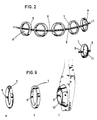
- a prefabricated splinting device is used, as is shown, for example, in FIG. 2.
- the device has a row of composite supports 7, the opposite wall parts of which each have a through hole 8, through which a wire (metal or plastic) 9 is pulled so that the composite supports 7 can be moved along the wire.
- the composite carriers 7 consist of a flexible plastic and are, for example, sections of an extruded plastic tube, so that they can be plastically deformed by finger pressure.
- Polymethyl methacrylate for example, is suitable as the starting material for the composite carrier 7.
- the wire 9 can either consist of stainless steel (metal) or a suitable plastic.
- This splinting device shown schematically in FIG. 2, is now applied to the tooth area to be connected after the intended fastening point has been pretreated with an etching agent, generally 40% phosphoric acid.
- an etching agent generally 40% phosphoric acid.
- the splint material which can be kept in stock by the meter, for example, is cut to the required length and approximately adapted to the curvature of the row of teeth in question.
- the composite carriers After the composite carriers have been placed on the intended fastening points, they can be optimally placed thanks to their displaceability on the wire 9 and their elastic deformability. In this treatment phase, all composite carriers 7 thus rest on the fastening points, while the wire 9 penetrates all composite carriers 7, but does not touch the tooth surfaces, but is guided at a distance from them.
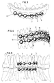
- Fig. 3 the splinting is shown again in the detail and on a somewhat larger scale using the example of a maxillary-side tooth fixation.
- the left half of the splint with the three composite carriers 7 located there is already attached to the adjacent tooth surfaces by means of composite material K, while the recesses A of the remaining three composite carriers 7 are still to be provided with composite material.
- fixation method can of course be combined with known fixation means, for example an additional wire ligation encompassing a single tooth.
- FIG. 4 A further application is shown in FIG. 4.
- connecting members 10 can be, for example, metallic, C-shaped, plastically bendable clamps, self-fixing plastic loops or simple wire ligatures.
- FIG. 5 The attachment of the described splint to the inner surfaces of the teeth (lingual and palatal) is shown schematically in FIG. 5.
- This type of splinting has the advantage, among other things, that it is invisible from the outside.
- an increase in splint stability can be achieved intramaxillary, intramandibular and also intermaxillary.
- the decisive element in the context of the present inventive concept is the composite carrier 7, which it allows to combine the simple use of the device with good wearing comfort and excellent stability.
- Three possible cross-sectional shapes of composite carriers 7, i.e. an annular bead a of circular cross-section, a cylindrical section b and a frustoconical variant c, are illustrated in FIG. 6, the adjacent tooth Z being indicated only in the case of the frustoconical variant c.
- the composite carrier 7 can be round, oval or polygonal as required.
- the two through holes 8 (FIG. 2) for the wire 9 do not necessarily have to lie diametrically opposite one another, but can also be offset from one another in special cases.
Landscapes
- Health & Medical Sciences (AREA)
- Veterinary Medicine (AREA)
- Life Sciences & Earth Sciences (AREA)
- Animal Behavior & Ethology (AREA)
- General Health & Medical Sciences (AREA)
- Public Health (AREA)
- Otolaryngology (AREA)
- Epidemiology (AREA)
- Oral & Maxillofacial Surgery (AREA)
- Dentistry (AREA)
- Pulmonology (AREA)
- Nursing (AREA)
- Orthopedic Medicine & Surgery (AREA)
- Engineering & Computer Science (AREA)
- Biomedical Technology (AREA)
- Heart & Thoracic Surgery (AREA)
- Vascular Medicine (AREA)
- Dental Tools And Instruments Or Auxiliary Dental Instruments (AREA)
Abstract
Description
Die vorliegende Erfindung betrifft eine Vorrichtung, wie sie im Oberbegriff des unabhängigen Patentanspruchs 1 definiert ist.The present invention relates to a device as defined in the preamble of independent claim 1.
Verletzungen im Zahn- und Kieferbereich führen in vielen Fällen zur Lockerung von Zähnen, die meistens noch gerettet werden können, vorausgesetzt, dass die erforderliche Notfallbehandlung rasch erfolgen kann. Im Rahmen einer derartigen Notfallbehandlung werden die traumatisierten Zähne reponiert und müssen dann anschliessend möglichst umgehend durch Schienung an den nicht luxierten Nachbarzähnen vorübergehend fixiert werden. Die sofortige Reposition und Schienung ist eine absolut vordringliche Voraussetzung einer erfolgreichen Behandlung wegen der raschen Degeneration des Restparodontes sowie der Bildung von Blutgerinnseln im Alveolenbereich, die das Repositionieren des luxierten Zahnes behindern. Auch besteht das Risiko, dass sich ein zunächst teilweise luxierter Zahn nach einer gewissen Zeit löst und in die Luftröhre gelangt.Injuries in the tooth and jaw area in many cases lead to loosening of teeth, which can usually still be saved, provided that the necessary emergency treatment can be given quickly. As part of such emergency treatment, the traumatized teeth are repositioned and then have to be temporarily fixed as quickly as possible by splinting on the non-luxated neighboring teeth. Immediate reduction and splinting is an absolutely essential requirement for successful treatment because of the rapid degeneration of the residual periodontium and the formation of blood clots in the alveolar area, which hinder the repositioning of the dislocated tooth. There is also the risk that a tooth that is initially partially luxated will come loose after a certain time and enter the trachea.
Schienungen im Zahnbereich können ferner zur Erzielung temporärer kieferchirurgischer Fixationen, und zwar intramandibulär, intramaxillär oder intermaxillär, erforderlich sein.Splinting in the tooth area may also be necessary to achieve temporary jaw fixations, namely intramandibular, intramaxillary or intermaxillary.
Gemäss einer bekannten, zur Zeit angewandten Technik wird der luxierte und reponierte Zahn mit seinen Nachbarzähnen mittels eines Metalldrahtes verbunden, der auf der Frontfläche der Zähne nach einer ätzenden Vorbehandlung durch ein Kompositmaterial fixiert wird. Die Anwendung dieser bekannten Methode erfordert eine spezielle Beherrschung von Material und Technik und kann so nur von einem Zahnarzt, nicht aber durch den in solchen Fällen meist zunächst zugezogenen bzw. verfügbaren Notfall- oder Hausarzt ausgeführt werden.According to a known, currently used technique, the luxated and repositioned tooth is connected to its neighboring teeth by means of a metal wire, which is fixed on the front surface of the teeth after an etching pretreatment by a composite material. The application of this The known method requires special mastery of material and technology and can therefore only be carried out by a dentist, but not by the emergency or general practitioner who is usually consulted or available in such cases.
Für die langfristige Nachbehandlung kieferorthopädischer Fälle ist es bekannt, starre, metallische Halteelemente, sogenannte "brackets", auf die Zahnoberfläche aufzukleben. Sämtliche dieser Halteelemente sind durch einen lose durch dieselben hindurchgeführten Metalldraht miteinander verbunden. Durch Spannen und erforderlichenfalls periodisches Nachspannen des Drahtes werden über die Halteelemente, welche in diesem Falle eine kraftübertragende Funktion haben, richtende Spannkräfte auf die zu behandelnden Zähne übertragen. Auch diese Methode kann nur von dem mit ihr vertrauten Zahnarzt angewandt werden; ausserdem erschwert die Starrheit der Halteelemente deren exakte Positionierung.For long-term follow-up treatment of orthodontic cases, it is known to stick rigid, metallic holding elements, so-called "brackets", to the tooth surface. All of these holding elements are connected to one another by a metal wire loosely guided through them. By tensioning and, if necessary, periodically re-tensioning the wire, directing tension forces are transmitted to the teeth to be treated via the holding elements, which in this case have a force-transmitting function. This method can only be used by the dentist who is familiar with it; in addition, the rigidity of the holding elements complicates their exact positioning.
Es ist auch schon versucht worden, eine Zahnschienung nur mit Kunststoff, das heisst ohne drahtförmiges Bindeglied, zu bewerkstelligen. Diese Methode konnte sich jedoch nicht durchsetzen, da es schwierig ist, den Kunststoff exakt zu formen und er andererseits den im Zahnbereich auftretenden Kräften oft nicht standhält. Auch hat sich die Entfernung des Kunststoffes als schwierig erwiesen.Attempts have also already been made to achieve tooth splinting only with plastic, that is to say without a wire-shaped link. However, this method could not prevail because it is difficult to form the plastic exactly and, on the other hand, it often does not withstand the forces occurring in the tooth area. Removing the plastic has also proven difficult.
Da das Kompositmaterial nach einer gewissen Zeit wieder entfernt werden muss, ist es von Bedeutung, dass von vornherein eine möglichst geringe Menge dieses Materials aufgetragen wird, die Klebefläche also möglichst exakt begrenzt wird, während andererseits aber doch das drahtförmige Bindeglied an der jeweiligen Befestigungsstelle sicher von Komposit umschlossen sein soll und die Bildung von Hohlstellen, insbesondere zwischen Draht und Zahnoberfläche, vermieden werden muss.Since the composite material has to be removed after a certain time, it is important that the smallest possible amount of this material is applied from the outset, that is to say the adhesive area is delimited as precisely as possible is, while on the other hand the wire-shaped link at the respective attachment point is to be securely enclosed by composite and the formation of hollows, in particular between the wire and the tooth surface, must be avoided.
Es ist die Aufgabe der vorliegenden Erfindung, eine Vorrichtung zur temporären passiven Schienung von Zähnen vorzuschlagen, die nicht nur von Zahnärzten, sondern insbesondere auch vom Hausarzt, dem Notfallarzt, dem Kieferchirurgen und gegebenenfalls auch von medizinischem Hilfspersonal risikolos angewandt werden kann.It is the object of the present invention to propose a device for temporary passive splinting of teeth which can be used risk-free not only by dentists, but in particular also by the family doctor, the emergency doctor, the maxillofacial surgeon and possibly also by medical assistants.
Die neue Vorrichtung soll einerseits die Anbringung des das drahtförmige Bindeglied an der Zahnoberfläche sichernden Komposits auf die effektiv notwendige Kompositmenge beschränken und es andererseits gestatten, die Lage der Befestigungsstelle an der Zahnoberfläche exakt zu wählen.The new device is intended, on the one hand, to restrict the attachment of the composite securing the wire-shaped link to the tooth surface to the amount of composite material that is actually necessary, and, on the other hand, to allow the location of the attachment point on the tooth surface to be selected exactly.
Die Erfindung ist im kennzeichnenden Teil des unabhängigen Patentanspruchs 1 definiert, wobei sich bevorzugte Ausführungsbeispiele aus den abhängigen Ansprüchen ergeben.The invention is defined in the characterizing part of independent patent claim 1, preferred exemplary embodiments resulting from the dependent claims.
Nachstehend werden einige Ausführungsbeispiele der erfindungsgemässen Vorrichtung unter Bezugnahme auf die beiliegende Zeichnung beschrieben.
- Fig. 1 veranschaulicht zunächst die Anwendung der erfindungsgemässen Vorrichtung an den Aussenflächen der maxilla- und mandibulaseitigen Zähne,
- Fig. 2 zeigt eine erste Ausführungsform der erfindungsgemässen Vorrichtung,
- Fig. 3 zeigt die Applizierung der Vorrichtung an der Aussenfläche einer maxillaseitigen Zahnreihe,
- Fig. 4 ist eine Frontansicht eines Zahnbereichs, welcher auf den Zahnaussenflächen sowohl maxilla- als auch mandibulaseitig geschient wurde, wobei beide Kieferpartien intermaxillär gekoppelt sind,
- Fig. 5 zeigt eine Anwendung auf den Zahninnenflächen lingual und palatinal,
- Fig. 6 zeigt einige mögliche Formen der Kompositträger und die
- Fig. 7 bis 11 veranschaulichen Anwendungsbeispiele an den oralen und/oder fazialen Oberflächen der maxilla- und/oder mandibulaseitigen Zahnpartien.
- 1 first illustrates the use of the device according to the invention on the outer surfaces of the maxilla and mandibula-side teeth,
- 2 shows a first embodiment of the device according to the invention,
- 3 shows the application of the device on the outer surface of a row of maxillary teeth,
- 4 is a front view of a tooth area which was splinted on both the maxilla and mandibula side on the outer tooth surfaces, both jaw parts being coupled intermaxillary,
- 5 shows an application on the inner surfaces of the teeth lingually and palatally,
- Fig. 6 shows some possible shapes of the composite carrier and the
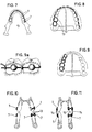
- 7 to 11 illustrate application examples on the oral and / or facial surfaces of the maxilla- and / or mandibula-side teeth.
Fig. 1 zeigt die Zahnreihen von Oberkiefer (Maxilla)1 und Unterkiefer (Mandibula)2 an welchen anschauungshalber eine Ausführungsform der erfindungsgemässen Vorrichtung dargestellt ist. An den Aussenflächen der mit 3 bzw. 4 bezeichneten Zähne sind Schienungen 5 bzw. 6 angebracht, wie sie beispielsweise erforderlich sein können, um einen traumatisierten Zahn an seinen Nachbarzähnen temporär zu fixieren oder um eine ganze Kieferpartie (beispielsweise bei Kieferbruch) vorübergehend ruhig zu stellen.1 shows the rows of teeth of the upper jaw (maxilla) 1 and lower jaw (mandible) 2, on which, by way of illustration, an embodiment of the device according to the invention is shown.
Zur exakten Abgrenzung der vorliegenden Erfindung sei zunächst darauf hingewiesen, dass dieselbe weder zur aktiven Schienung noch zur langfristigen orthopädischen Behandlung von Zahnstellungs- bzw. Kieferanomalien gedacht ist. Der Anwendungsbereich der erfindungsgemässen Vorrichtung liegt ausschliesslich in der temporären passiven Fixation von Zähnen, Zahnreihen oder Kieferpartien, wobei in erster Linie an die unmittelbar nach Unfällen bzw. chirurgischen Eingriffen zu ergreifenden Massnahmen gedacht ist, die bisher ohne Beizug eines sachkundigen Zahnarztes oder Kieferchirurgen nicht ausgeführt werden konnten, die aber dank der erfindungsgemässen Lehre nun auch von dem nach einem Unfall oder einer Operation anwesenden Betreuungspersonal (Hausarzt, Notfallarzt, Chirurg, Pflegepersonal) dank der einfachen Applikationsmöglichkeit ohne weiteres durchführbar sind.For the exact delimitation of the present invention, it should first be pointed out that it is not intended either for active splinting or for long-term orthopedic treatment of tooth position or jaw anomalies. The field of application of the device according to the invention lies exclusively in the temporary passive fixation of teeth, rows of teeth or parts of the jaw, primarily the measures to be taken immediately after accidents or surgical interventions, which have so far not been carried out without the involvement of a competent dentist or oral surgeon could, which thanks to the teaching according to the invention can now be carried out easily by the care personnel present after an accident or an operation (family doctor, emergency doctor, surgeon, nursing staff) thanks to the simple application possibility.
Es wird demnach zwecks Anwendung der erfindungsgemässen Vorrichtung vorausgesetzt, dass eventuell traumatisch dislozierte Zähne vorab reponiert wurden und demnach nur noch eine vorübergehende Fixierung erforderlich ist.For the purpose of using the device according to the invention, it is therefore assumed that possibly traumatically dislodged teeth have been repositioned beforehand and that therefore only a temporary fixation is required.
Zu diesem Zwecke wird eine vorgefertigte Schienungsvorrichtung verwendet, wie sie beispielsweise in Fig. 2 dargestellt ist. Die Vorrichtung weist eine Reihe Kompositträger 7 auf, deren einander gegenüberliegende Wandteile jeweils eine Durchgangsbohrung 8 aufweisen, durch welche ein Draht (Metall oder Kunststoff) 9 so hindurchgezogen ist, dass sich die Kompositträger 7 längs des Drahtes verschieben lassen.For this purpose, a prefabricated splinting device is used, as is shown, for example, in FIG. 2. The device has a row of composite supports 7, the opposite wall parts of which each have a through
Die Kompositträger 7 bestehen aus einem flexiblen Kunststoff und sind beispielsweise Abschnitte eines extrudierten Kunststoffschlauches, so dass sie sich durch Fingerdruck plastisch verformen lassen. Als Ausgangsmaterial kommt für die Kompositträger 7 beispielsweise Polymethylmethacrylat in Frage. Der Draht 9 kann entweder aus rostfreiem Stahl (Metall) oder einem geeigneten Kunststoff bestehen.The
Diese in Fig. 2 schematisch dargestellte Schienungsvorrichtung wird nun auf die zu verbindende Zahnpartie aufgebracht, nachdem die vorgesehene Befestigungsstelle mit einem Aetzmittel, im allgemeinen 40%iger Phosphorsäure, vorbehandelt wurde. Zu diesem Zwecke wird das Schienungsmaterial, das beispielsweise als Meterware vorrätig gehalten werden kann, auf die erforderliche Länge abgeschnitten und der Krümmung der betreffenden Zahnreihe annähernd angepasst. Nachdem die Kompositträger auf die vorgesehenen Befestigungsstellen aufgelegt wurden, lassen sich dieselben dank ihrer Verschiebbarkeit auf dem Draht 9 und ihrer elastischen Verformbarkeit optimal plazieren. In dieser Behandlungsphase liegen somit sämtliche Kompositträger 7 auf den Befestigungsstellen auf, während der Draht 9 sämtliche Kompositträger 7 durchdringt, die Zahnoberflächen jedoch nicht berührt, sondern im Abstand vor denselben geführt ist. Nun werden die von den Kompositträgern 7 umgrenzten Ausnehmungen A mit Kompositmaterial (K) ausgefüllt und überschüssiges Kompositmaterial abgestreift. Damit ist auf einfache Weise eine angenehm zu tragende Fixierung erzielt, die sich - falls das erforderliche Zubehör verfügbar ist - auch von Nichtdentisten in kürzester Frist anbringen lässt.This splinting device, shown schematically in FIG. 2, is now applied to the tooth area to be connected after the intended fastening point has been pretreated with an etching agent, generally 40% phosphoric acid. For this purpose, the splint material, which can be kept in stock by the meter, for example, is cut to the required length and approximately adapted to the curvature of the row of teeth in question. After the composite carriers have been placed on the intended fastening points, they can be optimally placed thanks to their displaceability on the
In Fig. 3 ist die Schienung am Beispiel einer maxillaseitigen Zahnfixation nochmals im Ausschnitt und in etwas grösserem Massstab dargestellt. Dabei ist die linke Hälfte der Schienung mit den dort befindlichen drei Kompositträgern 7 bereits mittels Kompositmaterial K an den angrenzenden Zahnoberflächen befestigt, während die Ausnehmungen A der restlichen drei Kompositträger 7 noch mit Kompositmaterial zu versehen sind.In Fig. 3, the splinting is shown again in the detail and on a somewhat larger scale using the example of a maxillary-side tooth fixation. The left half of the splint with the three
Sollte sich die Fixationsmethode in Einzelfällen als unzureichend erweisen, so kann sie selbstverständlich mit bekannten Fixationsmitteln, beispielsweise einer einen einzelnen Zahn umgreifenden zusätzlichen Drahtligatur, kombiniert werden.Should the fixation method prove inadequate in individual cases, it can of course be combined with known fixation means, for example an additional wire ligation encompassing a single tooth.
Eine weitere Anwendung zeigt Fig. 4. Hier mag beispielsweise das Erfordernis vorliegen, Maxilla und Mandibula im Hinblick auf die Heilung eines Kieferbruches vorübergehend aneinander zu fixieren, um die Bruchstelle dadurch während der ersten Periode der Heilungszeit ruhig zu stellen. Es sind in diesem Falle sowohl die Aussenflächen der oberen (maxillaseitigen) als auch die der unteren (mandibulaseitigen) Zähne mit einer Schienung versehen. Zur gegenseitigen, "intermaxillären" Verbindung der beiden Kiefer sind die beiden Drähte 9 mittels Verbindungsorganen 10 aneinandergekoppelt. Diese Verbindungsorgane 10 können beispielsweise metallische, C-förmige, plastisch verbiegbare Klammern, selbstfixierende Plastikschlaufen oder auch einfache Drahtligaturen sein.A further application is shown in FIG. 4. Here, for example, there may be a need to temporarily fix the maxilla and mandible to one another with a view to healing a broken jaw, in order to thereby immobilize the fracture during the first period of the healing period. In this case, both the outer surfaces of the upper (maxilla-side) and those of the lower (mandibula-side) teeth are provided with splinting. For the mutual, "intermaxillary" connection of the two jaws, the two
Die Anbringung der beschriebenen Schiene an den Zahninnenflächen (lingual und palatinal) zeigt schematisch Fig. 5. Diese Art der Schienung hat unter anderem den Vorteil, dass sie von aussen unsichtbar ist. In Verbindung mit Schienen an der Zahnaussenfläche ist eine Erhöhung der Schienungsstabilität intramaxillär, intramandibulär sowie auch intermaxillär erreichbar.The attachment of the described splint to the inner surfaces of the teeth (lingual and palatal) is shown schematically in FIG. 5. This type of splinting has the advantage, among other things, that it is invisible from the outside. In conjunction with splints on the outer surface of the tooth, an increase in splint stability can be achieved intramaxillary, intramandibular and also intermaxillary.
Das im Rahmen des vorliegenden Erfindungsgedankens ausschlaggebende Element ist der Kompositträger 7, der es gestattet, die einfache Anwendung der Vorrichtung mit gutem Tragkomfort und ausgezeichneter Stabilität zu verbinden. Drei mögliche Querschnittsformen von Kompositträgern 7, das heisst ein Ringwulst a von kreisförmigem Querschnitt, ein zylindrischer Abschnitt b und eine kegelstumpfförmige Variante c, sind in Fig. 6 veranschaulicht, wobei nur bei der kegelstumpfförmigen Variante c der angrenzende Zahn Z angedeutet ist. Hier ist ersichtlich, wie das Kompositmaterial 11 den vom Kompositträger 7 umgrenzten Hohlraum ausfüllt, dabei den von der Zahnoberfläche im Abstand befindlichen Draht 9 allseitig umschliesst und sowohl den Kompositträger 7 als auch den Draht 9 sicher mit der Zahnoberfläche verbindet. Die Kompositträger 7 können je nach Bedarf rund, oval oder auch polygonal sein. Die beiden Durchgangslöcher 8 (Fig. 2) für den Draht 9 müssen nicht unbedingt diametral einander gegenüberliegen, sondern können in Sonderfällen auch gegeneinander versetzt sein.The decisive element in the context of the present inventive concept is the
Die Hauptanwendungen der beschriebenen Schienung sind in den Fig. 7 bis 11 nochmals schematisch dargestellt. Es zeigen
- Fig. 7 eine intramandibuläre buccale Schienung, mit an zwei Zähnen angebrachter Drahtligatur 13,
- Fig. 8 eine intramaxilläre buccale Schienung, ebenfalls mit zusätzlicher, zweifacher Sicherung durch Drahtligatur 13,
- Fig. 9 eine beidseitige, das heisst buccal/linguale Schienung, wobei die Drähte der beiden Schienungen mittels Drahtligaturen 12 verbunden sind,
- Fig. 10 eine intramaxilläre und intramandibuläre Fixation, die durch lokale Drahtligaturen 13 gesichert ist und
- Fig. 11 eine intermaxilläre Fixation, bei welcher die Schienendrähte der beiden Kiefer mittels plastisch verbiegbarer Metallklammern, selbstfixierender Kunststoffschlaufen oder Drahtligaturen 14 aneinander gesichert sind.
- 7 is an intramandibular buccal splint with
wire ligature 13 attached to two teeth, - 8 an intramaxillary buccal splinting, also with additional, double securing by
wire ligature 13, - 9 shows bilateral, ie buccal / lingual splinting, the wires of the two splintings being connected by means of wire ligatures 12,
- 10 shows an intramaxillary and intramandibular fixation which is secured by local wire ligatures 13 and
- 11 shows an intermaxillary fixation in which the splint wires of the two jaws are secured to one another by means of plastically bendable metal clips, self-fixing plastic loops or wire ligatures 14.
Es versteht sich, dass weitere Ausformungen der beschriebenen Kompositträger im Bereich des fachmännischen Wissens und Könnens liegen.It goes without saying that further forms of the described composite carriers lie in the area of professional knowledge and ability.
Claims (6)
- Device for the temporary passive fixation of teeth, teeth rows or jaw parts in the case of tooth dislocation and in the case of surgical interventions on jaws, whereby a wire-shaped connecting link is anchored on the outer (facial) and/or inner (oral) surfaces of several neighbouring teeth, characterized in that a row of composite carriers (7) made of a flexible synthetic material are movably arranged on said wire-shaped connecting link (9), which composite carriers are intended to locally limit the composite material (K) to be applied and to ensure correct fixation of the wire-shaped connecting link (9) on the tooth surface, whereby each composite carrier (7) bounds a recess (A) which is adapted to receive and limit spreading of said composite material to be applied to the tooth surface, and said wire-shaped connecting link (9) passes through each of the composite carrier walls lying oppositely to each other in such a way that after its affixation at a distance to the teeth surfaces and after application of said composite material it is surrounded on all sides by said composite material.
- Device according to claim 1, characterized in that the composite carriers (7) comprise on each of two sides which lie substantially opposite one another, a through hole (8), through which the wire-shaped connecting link is guided.
- Device according to either claim 1 or 2, characterized in that the composite carriers (7) have an ergonomic design.
- Device according to claim 3, characterized in that the composite carriers (7) comprise hook-like appendages (15).
- Device according to claim 3, characterized in that the composite carriers (7) comprise openings (16, 17) for filling the composite carriers (7) and for curing the composite material.
- Device according to one of claims 1 to 3, characterized in that the wire-shaped connecting link (9) is made of a stainless steel or an elastically deformable biocompatible material, and the composite carriers (7) are made of a plastically deformable synthetic material.
Applications Claiming Priority (3)
| Application Number | Priority Date | Filing Date | Title |
|---|---|---|---|
| CH313189 | 1989-08-29 | ||
| CH3131/89 | 1989-08-29 | ||
| PCT/CH1990/000202 WO1991003212A1 (en) | 1989-08-29 | 1990-08-28 | Device for temporarily supporting teeth |
Publications (2)
| Publication Number | Publication Date |
|---|---|
| EP0441923A1 EP0441923A1 (en) | 1991-08-21 |
| EP0441923B1 true EP0441923B1 (en) | 1995-10-25 |
Family
ID=4249289
Family Applications (1)
| Application Number | Title | Priority Date | Filing Date |
|---|---|---|---|
| EP90912138A Expired - Lifetime EP0441923B1 (en) | 1989-08-29 | 1990-08-28 | Device for temporarily supporting teeth |
Country Status (5)
| Country | Link |
|---|---|
| US (1) | US5184955A (en) |
| EP (1) | EP0441923B1 (en) |
| AT (1) | ATE129401T1 (en) |
| DE (1) | DE59009819D1 (en) |
| WO (1) | WO1991003212A1 (en) |
Families Citing this family (24)
| Publication number | Priority date | Publication date | Assignee | Title |
|---|---|---|---|---|
| DE3943098C2 (en) * | 1989-12-27 | 1997-01-23 | Krenkel Christian | Establishment or regulation of the mutual position of teeth |
| US5846245A (en) * | 1995-10-20 | 1998-12-08 | New York University | Bone-adjusting device |
| US5931667A (en) * | 1997-07-14 | 1999-08-03 | Papandreas; Samuel G. | Orthodontic apparatus and method |
| US6086365A (en) * | 1998-02-02 | 2000-07-11 | Walter Lorenz Surgical, Inc. | Bonded intermaxillary fixation splint |
| US5964589A (en) * | 1998-03-05 | 1999-10-12 | Musich; David R. | Orthodontic arch stabilization device and method |
| WO2002013716A1 (en) * | 2000-08-16 | 2002-02-21 | Medartis Ag | Dental splint |
| CA2320455A1 (en) | 2000-09-22 | 2002-03-22 | Ewmc International Inc. | Medical waste unit |
| US20030044754A1 (en) * | 2001-09-05 | 2003-03-06 | Deslauriers Richard J. | Direct bonding dental arch bar |
| US7354270B2 (en) * | 2003-12-22 | 2008-04-08 | Align Technology, Inc. | Surgical dental appliance |
| US20060078849A1 (en) * | 2004-10-12 | 2006-04-13 | Parks Cynthia D | Dental splint |
| US7377782B1 (en) * | 2005-04-21 | 2008-05-27 | James Brosnihan | System and method for reimplanting avulsed teeth |
| US7351058B2 (en) * | 2006-02-14 | 2008-04-01 | Frank Fore | Arch bar |
| US20080057460A1 (en) * | 2006-08-30 | 2008-03-06 | Hicks Craig S | Anchor-based fixed retainers |
| US20230031165A1 (en) * | 2006-10-16 | 2023-02-02 | Rtrs Investment, Llc | Methods of Designing and Manufacturing Customized Dental Prosthesis For Periodontal or Osseointegration and Related Systems |
| US8303300B2 (en) * | 2009-02-17 | 2012-11-06 | Lewis Pitnick | Intermaxillary fixation bonded bracket assembly |
| US9662182B2 (en) | 2010-08-02 | 2017-05-30 | Thomas Williams | Dental splint device and methods for making and using same |
| EP2822500B1 (en) * | 2012-03-05 | 2019-09-04 | 3M Innovative Properties Company | Flexible orthodontic splint |
| US9554936B2 (en) | 2012-05-07 | 2017-01-31 | Lawrence D. Singer | Singer-Domanski resin MMF/reimplantation device |
| US10070944B2 (en) | 2012-05-07 | 2018-09-11 | Lawrence D. Singer | Singer-domanski resin MMF/reimplantation device |
| CN107405176B (en) * | 2015-03-13 | 2020-03-31 | 3M创新有限公司 | Orthodontic appliance including arcuate member |
| WO2016183457A1 (en) * | 2015-05-14 | 2016-11-17 | Haralambidis Cosmo | Orthodontic retention components, kit and system |
| US11452578B2 (en) * | 2015-05-14 | 2022-09-27 | Cosmo Haralambidis | Orthodontic retention components, kit and system |
| WO2020220095A1 (en) * | 2019-05-01 | 2020-11-05 | Erskine Holdco Pty Ltd | Orthodontic methods and devices |
| GB2631267B (en) | 2023-06-22 | 2025-07-30 | Abela Stefan | Orthodontic retainer positioning device |
Family Cites Families (11)
| Publication number | Priority date | Publication date | Assignee | Title |
|---|---|---|---|---|
| US3337957A (en) * | 1965-04-09 | 1967-08-29 | Marvin W Reed | Apparatus for stabilizing traumatized teeth |
| US3505736A (en) * | 1967-07-11 | 1970-04-14 | Allen C Brader | Mechanical arch form with plurality of integral arch form attachments |
| US3903601A (en) * | 1974-07-11 | 1975-09-09 | Modcom Inc | Dispenser for orthodontic chain-formed intraoral devices |
| US4107844A (en) * | 1976-11-15 | 1978-08-22 | Kurz Craven H | Orthodontic appliance |
| US4230104A (en) * | 1978-01-23 | 1980-10-28 | Richter Alice E | Splints for treating jaw fractures |
| US4433960A (en) * | 1981-07-13 | 1984-02-28 | Garito Jon C | Extracoronal dental splint and splinting method |
| US4504229A (en) * | 1981-07-13 | 1985-03-12 | Garito Jon C | Dental placement devices and methods |
| US4533320A (en) * | 1984-07-26 | 1985-08-06 | Jack Piekarsky | Stabilizing retainer system |
| NL8701879A (en) * | 1987-08-11 | 1989-03-01 | Marinus Bastiaan Guis | METHOD FOR APPLYING AN ORTHODONTIC WIRE BRACKET. |
| US4904188A (en) * | 1988-05-20 | 1990-02-27 | Harold Baurmash | Direct bonded arch bar for maxillo-mandibular injuries |
| US4915630A (en) * | 1989-05-15 | 1990-04-10 | Honig Gordon C | Dental splint |
-
1990
- 1990-08-28 DE DE59009819T patent/DE59009819D1/en not_active Expired - Fee Related
- 1990-08-28 US US07/675,893 patent/US5184955A/en not_active Expired - Fee Related
- 1990-08-28 EP EP90912138A patent/EP0441923B1/en not_active Expired - Lifetime
- 1990-08-28 AT AT90912138T patent/ATE129401T1/en not_active IP Right Cessation
- 1990-08-28 WO PCT/CH1990/000202 patent/WO1991003212A1/en not_active Ceased
Also Published As
| Publication number | Publication date |
|---|---|
| DE59009819D1 (en) | 1995-11-30 |
| ATE129401T1 (en) | 1995-11-15 |
| US5184955A (en) | 1993-02-09 |
| EP0441923A1 (en) | 1991-08-21 |
| WO1991003212A1 (en) | 1991-03-21 |
Similar Documents
| Publication | Publication Date | Title |
|---|---|---|
| EP0441923A1 (en) | Device for temporarily supporting teeth. | |
| EP1309287B1 (en) | Dental splint | |
| DE69930174T2 (en) | Orthodontic anchoring device | |
| DE69227228T2 (en) | BONE ANCHOR | |
| EP0372316B1 (en) | Orthodontic treatment device | |
| EP2062548B1 (en) | Medicinal membrane for bone regeneration | |
| DE3788108T2 (en) | Orthodontic devices for stretching a dental arch. | |
| EP1385435B1 (en) | Orthodontic and/or orosurgical device | |
| EP1379193B1 (en) | Orthodontic appliance | |
| DE69722315T2 (en) | Subperiosteal bone anchor | |
| DE19936061B4 (en) | Device for introducing implants | |
| US5829971A (en) | Osteodistraction device for use in mandibular distraction osteogenesis and a method of making the device | |
| WO2007095577A2 (en) | Improved arch bar | |
| DE3640933A1 (en) | Split, fixed dental bridge | |
| DE29820487U1 (en) | Lateral jaw implant | |
| DE102007005479B4 (en) | System for palatal enlargement | |
| EP2727554B1 (en) | Oral orthopedic device for forward displacement of the lower jaw | |
| DE3732128A1 (en) | Implant | |
| DE102018132984B4 (en) | Interdental screw | |
| EP4366655A1 (en) | Splint for treating tooth misalignments with a device for fastening the splint and production method thereof | |
| DE19824371A1 (en) | Orthopedic dental appliance with fixtures and guide element | |
| DE202005004941U1 (en) | System for extending of palate, comprising overlapping metal bow and central spreading unit | |
| DE202018107298U1 (en) | Interdental screw (Interdental screw) | |
| DE102021113317B4 (en) | Distraction system | |
| DE102020108709B4 (en) | Suction device for sucking liquid from a patient's oral cavity and suction system |
Legal Events
| Date | Code | Title | Description |
|---|---|---|---|
| PUAI | Public reference made under article 153(3) epc to a published international application that has entered the european phase |
Free format text: ORIGINAL CODE: 0009012 |
|
| 17P | Request for examination filed |
Effective date: 19910418 |
|
| AK | Designated contracting states |
Kind code of ref document: A1 Designated state(s): AT CH DE FR GB IT LI NL SE |
|
| RAP3 | Party data changed (applicant data changed or rights of an application transferred) |
Owner name: HIRSBRUNNER, EDUARD, DR. Owner name: BAER, HANS, DR. |
|
| 17Q | First examination report despatched |
Effective date: 19921127 |
|
| GRAA | (expected) grant |
Free format text: ORIGINAL CODE: 0009210 |
|
| AK | Designated contracting states |
Kind code of ref document: B1 Designated state(s): AT CH DE FR GB IT LI NL SE |
|
| REF | Corresponds to: |
Ref document number: 129401 Country of ref document: AT Date of ref document: 19951115 Kind code of ref document: T |
|
| ITF | It: translation for a ep patent filed | ||
| REF | Corresponds to: |
Ref document number: 59009819 Country of ref document: DE Date of ref document: 19951130 |
|
| REG | Reference to a national code |
Ref country code: CH Ref legal event code: NV Representative=s name: RITSCHER & SEIFERT PATENTANWAELTE VSP |
|
| GBT | Gb: translation of ep patent filed (gb section 77(6)(a)/1977) |
Effective date: 19960106 |
|
| ET | Fr: translation filed | ||
| PG25 | Lapsed in a contracting state [announced via postgrant information from national office to epo] |
Ref country code: GB Effective date: 19960828 |
|
| PLBE | No opposition filed within time limit |
Free format text: ORIGINAL CODE: 0009261 |
|
| STAA | Information on the status of an ep patent application or granted ep patent |
Free format text: STATUS: NO OPPOSITION FILED WITHIN TIME LIMIT |
|
| 26N | No opposition filed | ||
| PG25 | Lapsed in a contracting state [announced via postgrant information from national office to epo] |
Ref country code: NL Effective date: 19970301 |
|
| REG | Reference to a national code |
Ref country code: CH Ref legal event code: PL |
|
| GBPC | Gb: european patent ceased through non-payment of renewal fee |
Effective date: 19960828 |
|
| NLV4 | Nl: lapsed or anulled due to non-payment of the annual fee |
Effective date: 19970301 |
|
| EUG | Se: european patent has lapsed |
Ref document number: 90912138.6 |
|
| REG | Reference to a national code |
Ref country code: FR Ref legal event code: ST |
|
| REG | Reference to a national code |
Ref country code: CH Ref legal event code: AEN Free format text: WEITERBEHANDLUNG GUTGEHEISSEN |
|
| PGFP | Annual fee paid to national office [announced via postgrant information from national office to epo] |
Ref country code: CH Payment date: 19970805 Year of fee payment: 8 |
|
| PGFP | Annual fee paid to national office [announced via postgrant information from national office to epo] |
Ref country code: DE Payment date: 19970818 Year of fee payment: 8 |
|
| PGFP | Annual fee paid to national office [announced via postgrant information from national office to epo] |
Ref country code: AT Payment date: 19970827 Year of fee payment: 8 |
|
| PGFP | Annual fee paid to national office [announced via postgrant information from national office to epo] |
Ref country code: SE Payment date: 19970908 Year of fee payment: 8 |
|
| NLXE | Nl: other communications concerning ep-patents (part 3 heading xe) |
Free format text: A REQUEST FOR RESTORATION TO THE PRIOR STATE HAS BEEN FILED ON 970729 |
|
| REG | Reference to a national code |
Ref country code: FR Ref legal event code: RN |
|
| PGFP | Annual fee paid to national office [announced via postgrant information from national office to epo] |
Ref country code: FR Payment date: 19971223 Year of fee payment: 8 |
|
| REG | Reference to a national code |
Ref country code: FR Ref legal event code: FC |
|
| PG25 | Lapsed in a contracting state [announced via postgrant information from national office to epo] |
Ref country code: AT Free format text: LAPSE BECAUSE OF NON-PAYMENT OF DUE FEES Effective date: 19980828 |
|
| PG25 | Lapsed in a contracting state [announced via postgrant information from national office to epo] |
Ref country code: SE Free format text: THE PATENT HAS BEEN ANNULLED BY A DECISION OF A NATIONAL AUTHORITY Effective date: 19980829 |
|
| PG25 | Lapsed in a contracting state [announced via postgrant information from national office to epo] |
Ref country code: LI Free format text: LAPSE BECAUSE OF NON-PAYMENT OF DUE FEES Effective date: 19980831 Ref country code: CH Free format text: LAPSE BECAUSE OF NON-PAYMENT OF DUE FEES Effective date: 19980831 |
|
| NLXE | Nl: other communications concerning ep-patents (part 3 heading xe) |
Free format text: THE REQUEST FOR RESTORATION TO THE PRIOR STATE AS PROVIDED FOR IN ART. 23 OF THE PATENTS ACT 1995 HAS BEEN REJECTED. |
|
| REG | Reference to a national code |
Ref country code: CH Ref legal event code: PL |
|
| PG25 | Lapsed in a contracting state [announced via postgrant information from national office to epo] |
Ref country code: FR Free format text: LAPSE BECAUSE OF NON-PAYMENT OF DUE FEES Effective date: 19990430 |
|
| EUG | Se: european patent has lapsed |
Ref document number: 90912138.6 |
|
| PG25 | Lapsed in a contracting state [announced via postgrant information from national office to epo] |
Ref country code: DE Free format text: LAPSE BECAUSE OF NON-PAYMENT OF DUE FEES Effective date: 19990601 |
|
| REG | Reference to a national code |
Ref country code: FR Ref legal event code: ST |
|
| PG25 | Lapsed in a contracting state [announced via postgrant information from national office to epo] |
Ref country code: IT Free format text: LAPSE BECAUSE OF NON-PAYMENT OF DUE FEES;WARNING: LAPSES OF ITALIAN PATENTS WITH EFFECTIVE DATE BEFORE 2007 MAY HAVE OCCURRED AT ANY TIME BEFORE 2007. THE CORRECT EFFECTIVE DATE MAY BE DIFFERENT FROM THE ONE RECORDED. Effective date: 20050828 |