EP0441936B1 - Circuits eliminateurs de bruit - Google Patents
Circuits eliminateurs de bruit Download PDFInfo
- Publication number
- EP0441936B1 EP0441936B1 EP90913296A EP90913296A EP0441936B1 EP 0441936 B1 EP0441936 B1 EP 0441936B1 EP 90913296 A EP90913296 A EP 90913296A EP 90913296 A EP90913296 A EP 90913296A EP 0441936 B1 EP0441936 B1 EP 0441936B1
- Authority
- EP
- European Patent Office
- Prior art keywords
- signal
- residual noise
- input
- negative
- input signal
- Prior art date
- Legal status (The legal status is an assumption and is not a legal conclusion. Google has not performed a legal analysis and makes no representation as to the accuracy of the status listed.)
- Expired - Lifetime
Links
- 230000001629 suppression Effects 0.000 title claims description 30
- 238000012545 processing Methods 0.000 claims abstract description 9
- 239000003990 capacitor Substances 0.000 claims description 17
- 230000005236 sound signal Effects 0.000 claims description 17
- 238000000034 method Methods 0.000 claims description 4
- 230000003247 decreasing effect Effects 0.000 claims 2
- 239000007943 implant Substances 0.000 description 13
- 230000002459 sustained effect Effects 0.000 description 9
- 230000000638 stimulation Effects 0.000 description 7
- 239000002131 composite material Substances 0.000 description 5
- 230000005669 field effect Effects 0.000 description 5
- 206010011878 Deafness Diseases 0.000 description 4
- 230000000694 effects Effects 0.000 description 4
- 238000001228 spectrum Methods 0.000 description 4
- 230000005540 biological transmission Effects 0.000 description 3
- 238000004891 communication Methods 0.000 description 3
- 238000010586 diagram Methods 0.000 description 3
- 210000002768 hair cell Anatomy 0.000 description 3
- 230000009467 reduction Effects 0.000 description 3
- 230000013707 sensory perception of sound Effects 0.000 description 3
- 230000008054 signal transmission Effects 0.000 description 3
- 230000008901 benefit Effects 0.000 description 2
- 230000008859 change Effects 0.000 description 2
- 210000003477 cochlea Anatomy 0.000 description 2
- 230000006835 compression Effects 0.000 description 2
- 238000007906 compression Methods 0.000 description 2
- 238000012937 correction Methods 0.000 description 2
- 230000006870 function Effects 0.000 description 2
- 210000005036 nerve Anatomy 0.000 description 2
- 238000012360 testing method Methods 0.000 description 2
- 230000001052 transient effect Effects 0.000 description 2
- 208000032041 Hearing impaired Diseases 0.000 description 1
- 238000004378 air conditioning Methods 0.000 description 1
- 210000004556 brain Anatomy 0.000 description 1
- 210000000860 cochlear nerve Anatomy 0.000 description 1
- 239000004020 conductor Substances 0.000 description 1
- 239000000470 constituent Substances 0.000 description 1
- 230000006378 damage Effects 0.000 description 1
- 231100000895 deafness Toxicity 0.000 description 1
- 208000016354 hearing loss disease Diseases 0.000 description 1
- 230000001771 impaired effect Effects 0.000 description 1
- 230000001976 improved effect Effects 0.000 description 1
- 230000001939 inductive effect Effects 0.000 description 1
- 238000012544 monitoring process Methods 0.000 description 1
- 230000008447 perception Effects 0.000 description 1
- BASFCYQUMIYNBI-UHFFFAOYSA-N platinum Chemical group [Pt] BASFCYQUMIYNBI-UHFFFAOYSA-N 0.000 description 1
- 230000000630 rising effect Effects 0.000 description 1
- 239000004065 semiconductor Substances 0.000 description 1
- 229920000260 silastic Polymers 0.000 description 1
- 230000003595 spectral effect Effects 0.000 description 1
- 230000004936 stimulating effect Effects 0.000 description 1
- 230000002123 temporal effect Effects 0.000 description 1
- 238000012546 transfer Methods 0.000 description 1
Images

Classifications
-
- G—PHYSICS
- G01—MEASURING; TESTING
- G01D—MEASURING NOT SPECIALLY ADAPTED FOR A SPECIFIC VARIABLE; ARRANGEMENTS FOR MEASURING TWO OR MORE VARIABLES NOT COVERED IN A SINGLE OTHER SUBCLASS; TARIFF METERING APPARATUS; MEASURING OR TESTING NOT OTHERWISE PROVIDED FOR
- G01D3/00—Indicating or recording apparatus with provision for the special purposes referred to in the subgroups
- G01D3/028—Indicating or recording apparatus with provision for the special purposes referred to in the subgroups mitigating undesired influences, e.g. temperature, pressure
- G01D3/032—Indicating or recording apparatus with provision for the special purposes referred to in the subgroups mitigating undesired influences, e.g. temperature, pressure affecting incoming signal, e.g. by averaging; gating undesired signals
Definitions
- This invention relates to the suppression of noise in signal transmissions and, more particularly, to the suppression of background noise in order to separate speech and speech-like signals from the background noise in an audio signal.
- background noise accompany speech in audio-communications systems that are designed primarily to transmit speech.
- types of background noise include, among others, the sounds from air conditioning systems, motors, other mechanical devices, background voices in a crowd and the hiss of white noise. All of these different types of noise exhibit certain temporal properties which distinguish them significantly from the sound made by a single talker.
- a number of common noise suppression systems have heretofore been developed, such as: Squelch systems, in which the primary purpose is to remove channel noise from a weak or non-existent radio frequency (RF) carrier; expansion/compression systems, such as the DBX (Registered Trade Mark) and the Dolby (Registered Trade Mark) expander/compressor; and, noise pulse eliminator circuits of various designs.
- Squelch systems in which the primary purpose is to remove channel noise from a weak or non-existent radio frequency (RF) carrier
- expansion/compression systems such as the DBX (Registered Trade Mark) and the Dolby (Registered Trade Mark) expander/compressor
- noise pulse eliminator circuits of various designs.
- Such conventional squelch systems operate to determine that the RF signal being received has a high signal-to-noise ratio, but do not examine the content of the RF signal to determine if the content of the signal is speech or background noise.
- the present invention determines what the content of the derived audio signal is and suppresses the background noise while retaining the speech signal.
- noise pulse eliminator arrangements of the prior art there is an attempt to examine the statistics of given wave forms, whether they be related to RF transmission systems or recording systems.
- the nature of the analysis performed in noise pulse eliminators differs greatly from the nature of the analysis performed in the present invention.
- noise burst eliminators are designed to delete rapid burst-type signals
- the present invention is designed to eliminate long sustained sounds.
- the difference in emphasis results in differences in methods and apparatus employed to achieve the desired results.
- the multiplier output signal is zero in the absence of signal energy from either of its two input signals. Accordingly, there is no multiplier output during the time that only background noise appears in the audio signal.
- the audio signal, including its background noise is amplified (multiplied) during the time that speech information appears therein.
- the present invention distinguishes over those described above, and in particular over the disclosure in US patent number 4,630,304 in that the background noise portion of the audio signal is removed in the case of the present invention, rather than being amplified along with the speech portion of the signal.
- the present invention is intended to suppress background noise in signal transmissions systems, particularly in those systems wherein speech parameters, for example the amplitudes of various parts of the speech signal, are extracted and then later reconstituted in some way, as for instance in cochlear implants, vocoders, speech recognizers and speech transmission data rate reduction systems.
- speech parameters for example the amplitudes of various parts of the speech signal
- cochlear implants for example the amplitudes of various parts of the speech signal
- vocoders for example the amplitudes of various parts of the speech signal
- speech transmission data rate reduction systems for the sake of convenience, the invention will be described herein in relation to the suppression of noise in a speech communication system utilized in a cochlear implant for the profoundly deaf; however, it is to be understood that the invention is not limited thereto, as it may be applied to other signal transmission systems and other devices.
- Cochlear implant systems seek to bypass these hair cells by presenting electrical stimulation to the auditory nerve fibres directly, leading to the perception of sound in the brain. There have been many ways described in the past for achieving this object. One of the more effective of these is the system shown and described in US patent number 4,532,930 to Crosby et al, entitled “Cochlear Implant System For An Auditory Prosthesis.”
- the Crosby et al patent described a cochlear implant system in which an electrode array comprising multiple platinum ring electrodes in a silastic carrier is implanted in the cochlea of the ear.
- the electrode array is connected to a multichannel receiver-stimulator unit, containing a semiconductor integrated circuit and other components, which is implanted in the patient adjacent the ear.
- the receiver-stimulator unit receives data information and power through a tuned coil via an inductive link with a patient-wearable external speech processor.
- the speech processor includes an integrated circuit and various components which are configured or mapped to emit data signals from an Erasable Programmable Read Only Memory (EPROM).
- EPROM Erasable Programmable Read Only Memory
- the EPROM is programmed to suit each patient's electrical stimulation perceptions which are determined through testing of the patient and the implanted stimulator/electrode.
- the testing is performed using a diagnostic and programming unit that is connected to the speech processor by an interface unit.
- the system allows use of various speech processing strategies, including dominant spectral peak and amplitude and compression of voice pitch, so as to include voiced sounds, unvoiced glottal sounds and prosodic information.
- the speech processing strategy employed is based on known psychophysical phenomena, and is customized to each individual patient by the use of the diagnostic and programming unit.
- Bi-phasic pulses are supplied to various combinations of electrodes by a switch controlled current sink in various modes of operation. Transmission of data is by a series of discrete data bursts which represent the chosen electrode(s), the electrode mode configuration, the stimulating current, and amplitude determined by the duration of the amplitude burst.
- a problem which recipients of cochlear implants frequently have is that background noise causes irritating and unnecessary stimulation.
- the implant patient who has impaired sound processing capability is unable, like a normal listener, to filter out easily or ignore such stimulations from background noise.
- a system for suppressing residual noise in the processing of an input signal representing the energy of two signal components being a slowly varying residual noise level component and a rapidly varying data component characterised in that said system comprises:
- a method of suppressing residual noise in the processing of an input signal representing the energy of two signal components being a slowly varying residual noise level component and a rapidly varying data component comprising the steps of:
- An input signal shown generally 10, is applied to system 1 via a conductor 11.
- the input signal 10 comprises a signal having both a slowly varying residual noise level component and a rapidly varying data component therein.
- Input signal 10 may comprise, for example, a rectified audio signal developed in the aforesaid Crosby et al patent number 4,532,930.
- the input signal 10 is connected as one input to a subtraction device 12, for example a summing amplifier.
- Line 16 is connected through line 17 to one input terminal of a comparator 18, for example an operational amplifier, another input terminal of which is connected to ground.
- Comparator 18 serves to sense when the output signal 15 tries to go negative.
- the output of comparator 18 is applied through line 19 to the gate of a field effect transistor 20, the source and drain terminals of which are connected across capacitor 14. Accordingly, if the output signal level parameter 15 starts to go negative, the field effect transistor 20 operates to discharge capacitor 14 until the output signal level parameter 15 is again positive.
- the capacitor 14 In operation, if a constant background noise is present in the input signal 10, the capacitor 14 will charge to the background noise level, and its voltage will be subtracted from the input signal 10 to provide the output signal level parameter 15.
- the current source 13, capacitor 14 and subtraction device 12 comprise a means that is coupled to the input portion of the noise suppression system 1 for adding to the input signal 10 a slowly varying negative signal in order to substantially eliminate the residual noise level component from the input signal and provide an output signal 15 corresponding essentially to the rapidly varying data component of the input signal.
- the comparator 18 serves as a means for sensing the output signal level parameter
- the field effect transistor 20 serves as a means responsive to the sensing of a negative value in the output signal level parameter for rapidly adding a positive signal to the signal being processed in order to prevent the output signal from going further negative.
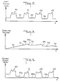
- Figure 2 is a graph showing input signal level plotted against time for the circuits shown in Figure 1, the parameter representing input signal level, expressed in terms of signal energy, envelope, mean value, or other measure of signal level, rather than the signal itself, rises and falls as speech is received.
- the parameter does not drop to zero, but drops to a plateau 42 which represents the residual noise level or noise floor.
- the parameter drops to the noise floor 44.
- the speech signal energy varies rapidly over tens or hundreds of milliseconds whereas the background noise, which for example may be due to a fan, an air conditioner or a car, varies more slowly over a period of tens of seconds.
- the noise suppression system of Figure 1 removes the slowly varying noise energy from the signal level parameter and preserves the more rapidly varying signal component.
- the noise suppression system 1 adapts to the reduction of the residual noise level and adjusts the minimum signal level output (noise floor plateau 46) to the patient's threshold, rather than providing above threshold stimulation.
- the time constant for charging capacitor 14 is preferably between 2 seconds and 10 seconds.
- the effect of using a short time constant, for example about 2 seconds, is that background noise is rapidly removed. However, sustained signals will also be removed.
- a longer time constant, for example about 10 seconds, will take longer to remove background noises.
- FIG. 5 an alternate embodiment of a noise suppression system according to the invention, employing a precision diode network, has there been illustrated generally at 2.
- the input signal 30 is AC coupled through a capacitor 31 to one input of an operational amplifier 32, the other input of which is connected to ground.
- the output of capacitor 31 is also connected to one side of a resistor 33, the other side of which is connected to ground.
- the output of the operational amplifier 32 is connected through a diode 34 to the output line 35 of the noise suppression system 2, and the output signal level parameter 36 appears at the downstream end of output line 35 during operation of the system.
- Resistor 33 serves to slowly and continuously drop the positive output level of the system, in order to bring the residual noise level floor to essentially zero. It thus corresponds to the function of the current source 13 and capacitor 14 of the Figure 1 embodiment.
- the operational amplifier 32 and diode 34 together, serve to clamp the output if the output signal level parameter 36 tries to drop below zero. In the event that the output signal level 36 does try to drop below zero, the capacitor 31 is quickly charged by amplifier 32 and diode 34 to restore the signal output level parameter to a positive value. Amplifier 32 and diode 34 thus correspond in function to comparator 18 and field effect transistor 20 of Figure 1 in this regard.
- the circuits of the noise suppression systems of Figures 1 and 5 are operating on a slowly changing parameter representing the signal level, expressed in terms of its energy, envelope or mean value, or other measure of signal level, rather than the signal itself.
- the systems operate equally well regardless of the measure of the signal level that is employed.
- the system is useful in cases where the signal is analyzed into its components of level and frequency (or frequency band) and is then reconstructed, such as the case, for example, in vocoders, some speech processing hearing aids and cochlear implants.
- cochlear implants as indicated earlier, the signal is analyzed into its parameters and presented to the patient in the form of electrical stimulation.
- the noise suppression system is applied to a number of frequency bands independently in the case of cochlear implants, so that if the noise spectrum is not uniform, the different noise plateaus at the different frequencies can still be correctly subtracted.
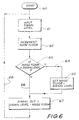
- FIG. 6 a flow chart representing a digital embodiment of a noise suppression system in accordance with the invention has there been illustrated generally at 3.
- the starting point of the flow chart is shown at 60. It represents a conventional initialization step during which an associated microprocessor (not shown) is initialized when the system is started up.
- the noise suppression algorithm would direct the system to sample the composite input signal level, as shown at 61. It would then increment the noise floor level, as shown at 62, and make a determination as to whether the noise floor level is greater than the composite signal input level, as shown at 63. If the noise floor level is greater than the signal level, as shown at 64, the noise floor level wold be reduced to equal the signal level, as shown at 65.
- an output signal is generated, as shown at 67, which is equal to the composite input signal level minus the noise floor level signal.
- the algorithm then loops back, as shown at 68, to again sample the composite input signal level, as shown at 61, and keeps repeating itself at a high rate during the time that the system is in operation.
- the improved noise suppression systems described herein remove the residual noise level in signals without affecting the presentation of the data in the signals. Moreover, such noise suppression systems rapidly compensate for changes in residual noise levels, or noise floors, and thus are particularly effective for use in devices that are utilised to aid hearing impaired and deaf persons to hear.
- the output signal from the system for suppressing residual noise has been referenced generally in the specification as a positive signal and a monitoring and correction arrangement has been described by which the output signal is maintained positive.
- Embodiments of the invention are envisaged where the frame of reference is inverted whereby the output signal is negative with respect to a reference and a corresponding correction arrangement is utilised to maintain the output signal negative with respect to the reference.
Landscapes
- Physics & Mathematics (AREA)
- General Physics & Mathematics (AREA)
- Noise Elimination (AREA)
Abstract
Claims (11)
- Un système de suppression de bruit résiduel dans le traitement d'un signal d'entrée représentant l'énergie de deux composantes de signal, l'une étant une composante de niveau de bruit résiduel lentement variable et une composante de données rapidement variable, système caractérisé en ce qu'il comprend :un premier moyen incluant un circuit possédant des parties d'entrée (11;30a) et de sortie (16;35) pour respectivement recevoir ledit signal d'entrée et émettre ladite composante de données de celui-ci;un second moyen (12, 13, 14 ; 33) couplé à ladite partie d'entrée (11) dudit premier moyen, pour additionner audit signal d'entrée un signal négatif/positif lentement variable pour éliminer substantiellement ladite composante de niveau de bruit résiduel dudit signal d'entrée et pour fournir un signal de sortie correspondant essentiellement à l'énergie de ladite composante de données rapidement variable dudit signal d'entrée;un troisième moyen (18,32) pour détecter ledit signal de sortie ; etun quatrième moyen (20, 34) répondant à la détection d'une valeur négative/positive dans ledit signal de sortie pour additionner rapidement un signal positif/négatif au signal d'entré en cours de traitement de manière à éviter audit signal d'entrée de devenir encore plus négatif/positif.
- Un système de suppression de bruit résiduel selon la revendication 1, dans lequel ledit signal d'entrée comprend un signal sonore redressé, lequel signal sonore possède une composante de bruit à basse fréquence
- Un système de suppression de bruit résiduel selon la revendication 2, dans lequel ledit second moyen comprend une résistance (33) connectée entre ladite partie d'entrée et la terre.
- Un système de suppression de bruit résiduel selon la revendication 2, dans lequel ledit second moyen comprend un générateur de courant (13), un condensateur (14) connecté en série avec lui, et un dispositif de soustraction (12) possèdant l'une de ses entrées connectée à ladite partie d'entrée dudit circuit et une autre de ses entrées connectée à un point intermédiaire entre ledit générateur de courant et ledit condensateur.
- Un système de suppression de bruit résiduel selon la revendication 2, dans lequel ledit troisième moyen comprend un amplificateur opérationnel (18) possèdant une première entrée connectée à la terre et une seconde entrée connectée pour recevoir ledit signal d'entrée.
- Un système de suppression de bruit résiduel selon la revendication 2, dans lequel ledit troisième moyen comprend un comparateur (32) ayant l'une de ses entrées connectée à la partie sortie dudit circuit et l'autre de ses entrées connectée à la terre.
- Un système de suppression de bruit résiduel selon la revendication 2, dans lequel ledit quatrième moyen comprend une diode (34) connectée entre ledit troisième moyen et ladite partie de sortie dudit premier moyen.
- Un système de suppression de bruit résiduel selon la revendication 2, dans lequel ledit quatrième moyen comprend un moyen formant porte (20) sensible audit troisième moyen et connecté en parallèle avec ledit second moyen pour diminuer sélectivement et rapidement tout signal de sortie continu (DC) négatif/positif détecté par ledit troisième moyen.
- Un système de suppression de bruit résiduel selon la revendication 1, dans lequel ladite composante de données comprend une partie sonore intelligible, et dans lequel ledit signal d'entrée comprend un signal sonore redressé.
- Une méthode de suppression de bruit résiduel dans le traitement d'un signal d'entrée représentant l'énergie de deux composantes de signal, l'une étant une composante de bruit résiduel lentement variable et l'autre une composante de données rapidement variable, comprenant les étapes de :addition audit signal d'entrée d'un signal négatif/positif lentement variable pour éliminer de façon substantielle ladite composante de niveau de bruit résiduel du signal d'entrée, et fournir un signal de sortie correspondant essentiellement à l'énergie de la composante de données rapidement variable dudit signal d'entrée;détection dudit signal de sortie ; etaddition d'un signal positif/négatif rapidement variable au signal en cours de traitement, lorsqu'un signal de sortie négatif/positif est détecté, de manière à éviter que ledit signal de sortie ne devienne encore plus négatif/positif.
- Une méthode de suppression de bruit résiduel selon la revendication 10, dans laquelle ledit signal positif/négatif rapidement variable est additionné au signal en cours de traitement en diminuant sélectivement rapidement le niveau du signal négatif/positif variable qui est en train d'être ajouté au signal d'entrée.
Applications Claiming Priority (3)
| Application Number | Priority Date | Filing Date | Title |
|---|---|---|---|
| AU6196/89 | 1989-09-06 | ||
| AUPJ619689 | 1989-09-06 | ||
| PCT/AU1990/000404 WO1991003890A1 (fr) | 1989-09-06 | 1990-09-06 | Circuits eliminateurs de bruit |
Publications (3)
| Publication Number | Publication Date |
|---|---|
| EP0441936A1 EP0441936A1 (fr) | 1991-08-21 |
| EP0441936A4 EP0441936A4 (en) | 1992-08-26 |
| EP0441936B1 true EP0441936B1 (fr) | 1996-12-11 |
Family
ID=3774169
Family Applications (1)
| Application Number | Title | Priority Date | Filing Date |
|---|---|---|---|
| EP90913296A Expired - Lifetime EP0441936B1 (fr) | 1989-09-06 | 1990-09-06 | Circuits eliminateurs de bruit |
Country Status (4)
| Country | Link |
|---|---|
| EP (1) | EP0441936B1 (fr) |
| CA (1) | CA2024528A1 (fr) |
| DE (1) | DE69029380T2 (fr) |
| WO (1) | WO1991003890A1 (fr) |
Cited By (1)
| Publication number | Priority date | Publication date | Assignee | Title |
|---|---|---|---|---|
| US9623242B2 (en) | 2015-07-10 | 2017-04-18 | Northwestern University | Methods of frequency-modulated phase coding (FMPC) for cochlear implants and cochlear implants applying same |
Family Cites Families (9)
| Publication number | Priority date | Publication date | Assignee | Title |
|---|---|---|---|---|
| US3816762A (en) * | 1973-01-02 | 1974-06-11 | Fairchild Camera Instr Co | Noise suppression circuit |
| US4025721A (en) * | 1976-05-04 | 1977-05-24 | Biocommunications Research Corporation | Method of and means for adaptively filtering near-stationary noise from speech |
| US4284856A (en) * | 1979-09-24 | 1981-08-18 | Hochmair Ingeborg | Multi-frequency system and method for enhancing auditory stimulation and the like |
| US4405831A (en) * | 1980-12-22 | 1983-09-20 | The Regents Of The University Of California | Apparatus for selective noise suppression for hearing aids |
| US4461025A (en) * | 1982-06-22 | 1984-07-17 | Audiological Engineering Corporation | Automatic background noise suppressor |
| US4630304A (en) * | 1985-07-01 | 1986-12-16 | Motorola, Inc. | Automatic background noise estimator for a noise suppression system |
| DE3735285A1 (de) * | 1987-10-17 | 1989-04-27 | Eckardt Ag | Schaltungsanordnung zur beseitigung von wechselspannungsstoersignalen |
| US4852175A (en) * | 1988-02-03 | 1989-07-25 | Siemens Hearing Instr Inc | Hearing aid signal-processing system |
| FI80173C (fi) * | 1988-05-26 | 1990-04-10 | Nokia Mobile Phones Ltd | Foerfarande foer daempning av stoerningar. |
-
1990
- 1990-09-04 CA CA 2024528 patent/CA2024528A1/fr not_active Abandoned
- 1990-09-06 WO PCT/AU1990/000404 patent/WO1991003890A1/fr not_active Ceased
- 1990-09-06 DE DE69029380T patent/DE69029380T2/de not_active Expired - Fee Related
- 1990-09-06 EP EP90913296A patent/EP0441936B1/fr not_active Expired - Lifetime
Non-Patent Citations (1)
| Title |
|---|
| THE BELL SYSTEM TECHNICAL JOURNAL vol. 60, no. 8, October 1981, NEW YORK, US pages 1847 - 1859; SONDHI ET AL.: 'Improving the quality of a noisy speech signal'& JP-A-58 206 238 * |
Cited By (1)
| Publication number | Priority date | Publication date | Assignee | Title |
|---|---|---|---|---|
| US9623242B2 (en) | 2015-07-10 | 2017-04-18 | Northwestern University | Methods of frequency-modulated phase coding (FMPC) for cochlear implants and cochlear implants applying same |
Also Published As
| Publication number | Publication date |
|---|---|
| DE69029380T2 (de) | 1997-07-10 |
| CA2024528A1 (fr) | 1991-03-07 |
| WO1991003890A1 (fr) | 1991-03-21 |
| EP0441936A1 (fr) | 1991-08-21 |
| DE69029380D1 (de) | 1997-01-23 |
| EP0441936A4 (en) | 1992-08-26 |
Similar Documents
| Publication | Publication Date | Title |
|---|---|---|
| McDermott et al. | A new portable sound processor for the University of Melbourne/Nucleus Limited multielectrode cochlear implant | |
| Gustafsson et al. | Masking of speech by amplitude‐modulated noise | |
| US7599742B2 (en) | Stimulation channel selection methods | |
| US8532317B2 (en) | Programmable auditory prosthesis with trainable automatic adaptation to acoustic conditions | |
| EP1359787B1 (fr) | Méthode d'adaptation et prothèse auditive basées sur les données de perte du rapport signal-bruit | |
| EP0787383B1 (fr) | Commande automatique de sensibilite | |
| US7219065B1 (en) | Emphasis of short-duration transient speech features | |
| US10463476B2 (en) | Body noise reduction in auditory prostheses | |
| EP1384319B1 (fr) | Commande a sensibilite variable pour implant cochleaire | |
| US20150005845A1 (en) | Reduction of Transient Sounds in Hearing Implants | |
| WO2003098970A1 (fr) | Prothese auditive programmable avec adaptation automatique par apprentissage aux conditions acoustiques | |
| US8223982B2 (en) | Audio path diagnostics | |
| WO2002089913A2 (fr) | Circuit electronique | |
| EP0441936B1 (fr) | Circuits eliminateurs de bruit | |
| McDermott et al. | Benefits of syllabic input compression for users of cochlear implants | |
| JP3151623B2 (ja) | ノイズ抑圧回路 | |
| AU2004240216B2 (en) | Programmable Auditory Prosthesis with Trainable Automatic Adaptation to Acoustic Conditions | |
| US10595134B1 (en) | Systems and methods for detecting and reacting to system noise generated by a cochlear implant system | |
| AU2002245950B2 (en) | Variable sensitivity control for a cochlear implant | |
| AU2002245950A1 (en) | Variable sensitivity control for a cochlear implant |
Legal Events
| Date | Code | Title | Description |
|---|---|---|---|
| PUAI | Public reference made under article 153(3) epc to a published international application that has entered the european phase |
Free format text: ORIGINAL CODE: 0009012 |
|
| AK | Designated contracting states |
Kind code of ref document: A1 Designated state(s): DE FR GB |
|
| 17P | Request for examination filed |
Effective date: 19910912 |
|
| A4 | Supplementary search report drawn up and despatched |
Effective date: 19920709 |
|
| AK | Designated contracting states |
Kind code of ref document: A4 Designated state(s): DE FR GB |
|
| 17Q | First examination report despatched |
Effective date: 19941207 |
|
| GRAG | Despatch of communication of intention to grant |
Free format text: ORIGINAL CODE: EPIDOS AGRA |
|
| GRAH | Despatch of communication of intention to grant a patent |
Free format text: ORIGINAL CODE: EPIDOS IGRA |
|
| GRAH | Despatch of communication of intention to grant a patent |
Free format text: ORIGINAL CODE: EPIDOS IGRA |
|
| GRAA | (expected) grant |
Free format text: ORIGINAL CODE: 0009210 |
|
| AK | Designated contracting states |
Kind code of ref document: B1 Designated state(s): DE FR GB |
|
| REF | Corresponds to: |
Ref document number: 69029380 Country of ref document: DE Date of ref document: 19970123 |
|
| ET | Fr: translation filed | ||
| PLBE | No opposition filed within time limit |
Free format text: ORIGINAL CODE: 0009261 |
|
| STAA | Information on the status of an ep patent application or granted ep patent |
Free format text: STATUS: NO OPPOSITION FILED WITHIN TIME LIMIT |
|
| 26N | No opposition filed | ||
| REG | Reference to a national code |
Ref country code: GB Ref legal event code: IF02 |
|
| PGFP | Annual fee paid to national office [announced via postgrant information from national office to epo] |
Ref country code: GB Payment date: 20040907 Year of fee payment: 15 Ref country code: DE Payment date: 20040907 Year of fee payment: 15 |
|
| PGFP | Annual fee paid to national office [announced via postgrant information from national office to epo] |
Ref country code: FR Payment date: 20040910 Year of fee payment: 15 |
|
| PG25 | Lapsed in a contracting state [announced via postgrant information from national office to epo] |
Ref country code: GB Free format text: LAPSE BECAUSE OF NON-PAYMENT OF DUE FEES Effective date: 20050906 |
|
| PG25 | Lapsed in a contracting state [announced via postgrant information from national office to epo] |
Ref country code: DE Free format text: LAPSE BECAUSE OF NON-PAYMENT OF DUE FEES Effective date: 20060401 |
|
| GBPC | Gb: european patent ceased through non-payment of renewal fee |
Effective date: 20050906 |
|
| PG25 | Lapsed in a contracting state [announced via postgrant information from national office to epo] |
Ref country code: FR Free format text: LAPSE BECAUSE OF NON-PAYMENT OF DUE FEES Effective date: 20060531 |
|
| REG | Reference to a national code |
Ref country code: FR Ref legal event code: ST Effective date: 20060531 |