EP0442036A2 - Procédé et appareil pour cambrer un ressort à lames - Google Patents
Procédé et appareil pour cambrer un ressort à lames Download PDFInfo
- Publication number
- EP0442036A2 EP0442036A2 EP90119182A EP90119182A EP0442036A2 EP 0442036 A2 EP0442036 A2 EP 0442036A2 EP 90119182 A EP90119182 A EP 90119182A EP 90119182 A EP90119182 A EP 90119182A EP 0442036 A2 EP0442036 A2 EP 0442036A2
- Authority
- EP
- European Patent Office
- Prior art keywords
- mold
- fingers
- molds
- leaf spring
- cambering
- Prior art date
- Legal status (The legal status is an assumption and is not a legal conclusion. Google has not performed a legal analysis and makes no representation as to the accuracy of the status listed.)
- Granted
Links
Images


Classifications
-
- B—PERFORMING OPERATIONS; TRANSPORTING
- B21—MECHANICAL METAL-WORKING WITHOUT ESSENTIALLY REMOVING MATERIAL; PUNCHING METAL
- B21D—WORKING OR PROCESSING OF SHEET METAL OR METAL TUBES, RODS OR PROFILES WITHOUT ESSENTIALLY REMOVING MATERIAL; PUNCHING METAL
- B21D53/00—Making other particular articles
- B21D53/88—Making other particular articles other parts for vehicles, e.g. cowlings, mudguards
- B21D53/886—Making other particular articles other parts for vehicles, e.g. cowlings, mudguards leaf springs
-
- B—PERFORMING OPERATIONS; TRANSPORTING
- B21—MECHANICAL METAL-WORKING WITHOUT ESSENTIALLY REMOVING MATERIAL; PUNCHING METAL
- B21F—WORKING OR PROCESSING OF METAL WIRE
- B21F37/00—Manufacture of rings from wire
-
- Y—GENERAL TAGGING OF NEW TECHNOLOGICAL DEVELOPMENTS; GENERAL TAGGING OF CROSS-SECTIONAL TECHNOLOGIES SPANNING OVER SEVERAL SECTIONS OF THE IPC; TECHNICAL SUBJECTS COVERED BY FORMER USPC CROSS-REFERENCE ART COLLECTIONS [XRACs] AND DIGESTS
- Y10—TECHNICAL SUBJECTS COVERED BY FORMER USPC
- Y10T—TECHNICAL SUBJECTS COVERED BY FORMER US CLASSIFICATION
- Y10T29/00—Metal working
- Y10T29/49—Method of mechanical manufacture
- Y10T29/49609—Spring making
- Y10T29/49611—Spring making for vehicle or clutch
Definitions
- This invention relates to a method of cambering a leaf spring and an apparatus therefor, particularly to a method which can greatly reduce the mold setup time and improve the production efficiency by eliminating the need of replacing the cambering molds in accordance with order changes and an apparatus therefor.
- Land transportation vehicles such as railway trains and trucks are provided with suitable suspension devices made by a plurality of leaf springs 10 as shown in Fig. 7.
- leaf spring 10 is made of a rolled material with a necessary thickness which is, after the process of opening an eyeend at one or both ends of a plate material, or tapering the other end thereof, given a necessary "deflection", or camber, in the state where the whole material is heated.
- cambers There are various types of cambers: the curvature gradually reduces or increases from the center toward both ends; the central part is formed flat, etc., depending on the use or load stress applied.
- Fig. 8 shows an example of prior art apparatus 12 for cambering leaf springs 10.
- the apparatus 12 basically consists of an upper mold 14 and a lower mold 16, and the upper mold 14 is of a female or concave shape, while the lower mold 16 of a male or convex shape.
- a leaf spring 10 immediately after being heated to the hot process temperature is inserted between these upper mold 14 and the lower mold 16, and then the upper mold 14 is forced to approach the lower mold 16 to give the plate 10 the camber in accordance with the shape of the molds 14 and 16.
- This cambered leaf spring 10 is then tempered by immersing it in a tempering oil carried within an oil tank.
- cambered leaf spring 10 is immersed in the oil without any constraint for carrying out tempering, it is distorted during the cooling process.
- a countermeasure for it is proposed in which the cambered leaf spring 10 is constrained as it is, and immersed in the oil in this state to prevent the distortion which may occur by the cooling.
- the distortion preventive means shown in Fig. 9 has a plurality of movable claw members 22 provided on a conveyor 20 circulatable in an oil tank 18, which are designed to mechanically hold a leaf spring material 10 at strategic positions.
- the leaf spring 10 to which the required camber has been given by said cambering apparatus 12 is held by a group of claws 22 locating at the carry-in side of the oil tank 18, and the conveyor 20 is then circulated with the leaf spring 10 as held thereon immersing them in the oil to carry out tempering.
- the distortion preventive means shown in Fig. 10 rotatably supports therein an octagonal column-shaped main body 24.
- the main body 24 has a cambering apparatus 12 on each surface and the lower part of the main body 24 is designed to be immersed into the oil tank 18.
- a heated straight leaf spring material 10 is loaded on the cambering apparatus 12 locating above the oil level and held between the upper mold 14 and the lower mold 16 to carry out cambering. Then, the main body 24 is rotated in the above state to immerse the cambered leaf spring 10 into the oil carried in the oil tank 18 as it is held between the upper mold 14 and the lower mold 16.
- the leaf spring material 10 is cambered by pressing it between an upper mold 14 and a lower mold 16 of the cambering apparatus 12, and then the cambering apparatus 12 is immersed into the oil carried in an oil tank 18.
- the cambering apparatus 12 within the oil tank 18 is circulatably fed by an appropriate carrying means to carry out tempering of the cambered leaf spring 10 loaded in the cambering apparatus 12.
- cambering apparatus 12 comprises a single cambering apparatus 12 which is designed to hold the plate spring 10 tightly between the upper mold 14 and the lower mold 16 and to immerse the thus held leaf spring 10 in the oil tank 18.
- the oil tank 18 is rocked by an appropriate rocking means so that the leaf spring 10 held by the cambering apparatus 12 may properly be tempered.
- cambered leaf springs 10 For manufacturing such cambered leaf springs 10, there are two kinds of methods; 1 to effect cambering of leaf springs 10 of the same shape and specification continuously by the group (the industry calls this method “Group making”), and 2 a family of leaf springs 10 from the main leaf 10 to the smaller leaves 10 constituting a suspension device are cambered (the industry calls this method "Family making”) . It depends on the users' choice considering the application and other factors which method is used for cambering leaf springs. In the Group making method, a required number of leaf springs of the same shape are cambered by the lot, and only when the shape of camber is changed, the upper mold 14 and the lower mold 16 of the cambering apparatus 12 are replaced.
- the Family making method the family of leaves are all allowed to have slightly different cambers, so that the upper mold 14 and the lower mold 16 have to be replaced each time one leaf 10 is cambered. Therefore, the latter method involves an extremely troublesome replacement work and increased loss time.
- the conventional cambering systems failed to meet the needs of the industry in this respect. Whether the Group making method or the Family making method it may be, many kinds of upper molds 14 and lower molds 16 corresponding to a variety of camber size requirements are necessary, leading to great increase in the production cost. Moreover, these molds have to be stored in groups of the same type, requiring an enormous storage space, giving rise to problems that their storage and maintenance are complicated and so on.
- the method mentioned referring to Fig. 12 has a merit of minimizing distortion compared with the methods shown in Figs. 9 through 11, but suffers a disadvantage of extremely low productivity. Further, the methods shown in Figs. 9 through 12 involve such common demerit that they require very troublesome work including adjustment of the claw members 22 for properly constraining the leaf springs 10 and for replacing the molds 14 and 16 according to the order changes of the leaf spring 10, and such setup procedures require much time. Moreover, the methods mentioned referring to Figs. 9 through 12 also suffer problems that, since the cambering apparatus 12 itself is immersed in the oil for carrying out tempering of the leaf springs, a number of molds 14 and 16 corresponding to the respective camber specifications have to be prepared, leading to increased production cost.
- this invention has been proposed to solve them in a suitable manner, and its object is to provide a novel method and an apparatus for cambering leaf spring materials which can improve the productivity by greatly reducing the time required for the setup of replacing the molds in accordance with the order changes.
- one aspect of this invention is to provide a method of cambering a leaf spring by loading a heated leaf spring material between a pair of molds retractably disposed so as to oppose each other and bringing these molds closer to hold said leaf spring material tightly therebetween to effect cambering thereof taking after the opposing surfaces of the molds, characterized in that: said pair of molds each comprise a plurality of mold fingers which can be advanced or retracted relative to the opposite mold; a plurality of drive means connected to said plurality of mold fingers are operated based on a predetermined command given from a control means to advance or retract said fingers to required heights, respectively, so that the free ends of the mold fingers as a whole may form a required mold surface; and each mold finger is locked with a releasable locking means.
- a second aspect of this invention is to provide an apparatus for cambering a leaf spring having a pair of molds retractably disposed so as to oppose each other, wherein said molds each comprise: a plurality of mold fingers constituting each mold which can be advanced or retracted relative to the opposite mold; a plurality of drive means connected to said plurality of mold fingers for advancing or retracting them to required heights, respectively; a control means giving control commands to the respective drive means to advance or retract the respective mold fingers so that the free ends of the mold fingers as a whole many form a required continuous mold surface; and a plurality of releasable locking means which immobilize the respective mold fingers after they are adjusted to required hights by the respective drive means.
- a third aspect of this invention is to provide a method of cambering a leaf spring which uses a pair of molds separably installed so as to oppose each other to effect cambering of a heated leaf spring material loaded therebetween taking after the opposing surfaces of said molds by bringing them closer to press the leaf spring material tightly therebetween, characterized in that: said pair of molds each comprises a plurality of mold fingers which can be advanced or retracted relative to the opposite mold; a plurality of drive means which can separably be connected respectively to said plurality of mold fingers are operated under a predetermined control command given from a control means to advance or retract the mold fingers to required heights, respectively, so that the free ends of the mold fingers as a whole may form a required continuous mold surface; each of said mold fingers is immobilized with a locking mechanism and said drive means are separated from said mold fingers; a leaf spring material is loaded between said molds to be pressed tightly therebetween to effect required cambering thereof, said two molds, together with the cambered leaf spring, are immer
- aspect of this invention is to provide an apparatus for cambering a leaf spring having a pair of molds separably disposed so as to oppose each other, characterized in that said apparatus comprises: an independent cassette unit consisting of a pair of molds each having a plurality of mold fingers which can be advanced or retracted relative to the opposite mold; a plurality of drive means which can separably be connected to said plurality of mold fingers to advance or retracted them relative to the opposite mold to required hights, respectively; a control means which gives control commands to the respective drive means to advance or retract said mold fingers so that the free ends of the mold fingers as a whole may form a required continuous mold surface; and a releasable locking mechanism for immobilizing said mold fingers which have been advanced or retracted to required heights, by the respective drive means.
- the mold fingers can automatically be positioned based on the numerical data inputted beforehand, change of mold shape in accordance with the order changes can be carried out speedily. Moreover, the mold adjustment requires no direct intervention of operators, leading to labor and power saving.
- the leaf springs can be immersed in the oil while they are constrained between the molds, so that any distortion which may otherwise occur during the tempering process can effectively be prevented.
- Fig. 1 shows schematically a constitution of the cambering apparatus in which the present method of cambering a leaf spring can suitably be realized.
- Fig. 2 shows schematically a perspective view of the mold finger adjustment mechanism.
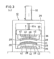
- Fig. 3 (a) through (c) explain the actions of the cambering apparatus shown in Fig. 1 with passage of time when it is operated.
- Fig. 4 shows schematically the constitution of another embodiment of the cambering/tempering apparatus according to this invention.
- Fig. 5 shows schematically a partially cutaway view of the hydraulic press shown in Fig. 4.
- Fig. 6 shows schematically a perspective view of the mold finger adjuster disposed in the setup unit shown in Fig. 4.
- Fig. 7 illustrates a suspension device comprising leaf springs.
- Fig. 8 illustrates a prior art cambering apparatus.
- Fig. 9 shows schematically a perspective view of a prior art tempering apparatus.
- Fig. 10 shows schematically a perspective view of a prior art cambering/tempering apparatus.
- Fig. 11 shows schematically a perspective view of another prior art cambering/tempering apparatus.
- Fig. 12 shows schematically a perspective view of still another prior art cambering/tempering apparatus.
- Fig. 1 shows schematically the constitution of an exemplary cambering apparatus.
- a lower mold 16 is disposed at the bottom of a rectangular base frame 26 with its mold fingers 28 (to be described later) directing upward, in which also disposed is a press head 30 to be descendable or ascendable.
- a press head 30 On the bottom surface of the press head 30 an upper mold 14 is fixed with its mold fingers 28 directing toward said lower mold 16.
- a fluid pressure cylinder preferably a hydraulic cylinder 32 is inversely disposed with its piston rod 32a extending into the base frame 26.
- the end of this piston rod 32a is connected to the press head 30.
- an adjustment mechanism 34 for changing the shape of the leaf spring cambering mold is provided on each of the upper mold 14 and the lower mold 16. Since the same kind of mechanism is used for molds 14 and 16, only the one for the lower mold 16 will now be explained, and as for the adjustment mechanism 34 in the upper mold 14 the corresponding members are indicated with the identical reference numbers only.
- a constituent of the lower mold 16 disposed are a multiplicity of mold fingers 28 with their tips protruding from the top surface of said holder 36 to predetermmed heights, respectively, said mold fingers 28 being capable of advancing or retracting vertically.
- These mold fingers 28 are arranged in parallel with one another along the length of said holder 36, so that the curve connecting their tips (upper ends) may form a continuous cambering mold shape.
- each mold finger 28 downwardly formed is a tapped hole 28a, into which a threaded shaft 38 is screwed.
- a threaded shaft 38 protruding downward from the mold finger 28, disposed, for example, is a bevel gear 40.
- servo motors 42 are provided in the number corresponding to that of said mold fingers 28, and a bevel gear 44 attached to the power shaft 42a of this motor 42 engages with the bevel gear 40 of the threaded shaft 38. Therefore, when the servo motor 42 is selectively rotated normally or reversely, the mold finger 28 is advanced or retracted, correspondingly.
- said threaded shaft 38 is provided with a brake 46 which functions as a locking mechanism to immobilize the mold finger 28 at an arbutray position after it has been advanced or retraced by the servo motor 42 to a required height.
- Said servo motor 42 is provided with a position detector 48 which detects the current position of the mold finger 28 by detecting the revolutional frequency of said motor 42, and the accurate position of the mold finger 28 can constantly be monitored thereby.
- the signal from the position detector 48 concerning the current position of the mold finger 28 is inputted to a control means (not shown) incorporating, for example, a micro-computer. Therefore, if data for the desired cambering mold shape are preliminarily inputted to this control means, the operation of the servo motor 42 can be controlled based on said data to facilitate changing of the mold shape to be formed by the mold fingers 28.
- a straight leaf spring 10 heated to a predetermined temperature is loaded between the upper mold 14 and the lower mold 16.
- the upper mold 14 is descended to press the leaf spring 10 tightly between the two molds 14 and 16 (see Fig. 3(b)). Since the mold shapes for obtaining a desired camber has been formed by the mold fingers on the opposing surfaces of the upper mold 14 and the lower mold 16 as described above, said leaf spring 10 is allowed to have the desired camber taking after said molds 14 and 16.
- the hydraulic cylinder 32 is reversely operated to ascend the upper mold 14, as shown in Fig. 3(c)
- the cambered leaf spring is taken out from the cambering apparatus 12 and forwarded to the subsequent process such as tempering, etc.
- the desired cambering mold shape can be formed on each of the opposing surfaces of the upper mold 14 and the lower mold 16 only by inputting the data of the desired camber shape to the control means, thus reducing the time required for the setup of the molds in accordance with the order changes and improving the production efficiency. Moreover, since there is no need of preparing a member of upper molds 14 and lower molds 16 corresponding to a variety of camber shapes, not only the production cost can be reduced but also the troublesome storage and maintenance of molds can be eliminated.
- the time required for the mold adjustment work can further be reduced if the data for a plurality of cambering mold shapes are preliminarily inputted to the control means so that the desired mold shape can be selected from them by pressing a proper set button in accordance with the order changes.
- Fig. 4 shows schematically a constitution of an examplary cambering/tempering apparatus in which the cambering method can suitably be practiced.
- the cambering/tempering apparatus 50 basically comprises an oil tank 18 installed in a pit 52 dug to a required depth from the installation surface, a hydraulic press 54 provided above said oil tank 18 at one longitudinal end protion, an unloading device 56 provided above said oil tank 18 at the other longitudinal end portion, and a setup unit 58 disposed at an appropriate position.
- the process of cambering and tempering a leaf spring 10 and changing of the shapes of the upper mold 14 and the lower mold 16 is performed by circulating the independent unit of cambering cassette 60 consisting of the upper mold 14 and the lower mold 16 within the cambering/tempering apparatus 50.
- a base frame 26 having a rectangular shape is installed on the top of the oil tank 18, and a hydraulic cylinder 32 is inversely provided on the top of this base frame 26 with the piston rod 32a thereof extending into the base frame 26.
- a head 61 is disposed to be ascendable or descendable, to which said piston rod 32a is connected. Accordingly, when the hydraulic cylinder 32 is driven in the positive or negative direction, the head 61 can be ascended or descended within the base frame 26.
- the head 61 of the hydraulic press 54 functions to descend the upper mold 14 in the cambering cassette 60 as described later, while the head 61 of the unloading device 56 functions to ascend said upper mold 14.
- a passage 62 for permitting said cambering cassette 60 is formed as shown in Fig. 4, and a pair of opposing support members 63 are pivotally disposed on each side of the passage 62.
- These support members 63 function to set and hold the cambering cassette 60 within the hydraulic press 54 and also to release said cassette 60 from said press 54 permitting it to descend into the oil tank 18.
- each of the support members 63 is adapted to extend its one end into the passage 62, while the other end thereof is connected to the piston rod 64a of the cylinder 64 installed within the base frame 26.
- the cambering cassette 60 consists of an upper mold 14 and a lower mold 16 which can be brought closer or farther relative to each other, and each mold comprises a multiplicity of mold fingers 28 disposed in each holder 36 in the same manner as in the foregoing embodiment.
- said cambering cassette 60 itself is immersed into the oil, so that the adjustment of the mold fingers is designed to be performed in a setup device 58 to be described later.
- a slot 65 is defined in each of the mold fingers 28, as shown in Fig. 6, and pivotal shafts 66 are inserted through the slots of all the mold fingers 28 disposed to the lower mold 16 and the upper mold 14, respectively.
- These pivotal shafts 66 are each designed to be turned within a predetermined angle range by means of a cam 67 and a cylinder 68 provided at one end thereof.
- an eccentric cam 69 is fixed on said pivotal shaft 66 at each position corresponding to the slot 65 of each finger 28. When the pivotal shaft 66 is turned, for example, clockwise, this eccentric cam 69 abuts against the inner wall of the slot 65 to prevent shifting off of the mold finger 28, whereas when the pivotal shaft 66 is turned counterclockwise, the finger 28 is designed to be shiftable.
- a hole 70 is formed at an appropriate position of each mold finger 28, which is used when the mold finger 28 is adjusted in the setup unit 58 to be described later.
- the setup unit 58 is for adjusting the protruding length of each mold finger 28 of the upper mold 14 and the lower mold 16 from the holder 36 to change the cambering mold shape to be formed thereby. While this apparatus has adjusters 75, as shown in Fig. 6, provided for each of the respective mold fingers 28 of the upper mold 14 and the lower mold 16, only one adjuster 75 is shown in the drawing.
- a threaded shaft 38 is rotatably supported between the upper and lower horizontal members 71, 71a thereof, and a servo motor 42 is attached on the upper end of said threaded shaft 38.
- a nut 73 On the threaded shaft 38, screwed is a nut 73 having a pin 72 screwed therein which can be inserted into the hole 70 formed in each mold finger 28.
- This nut 73 is designed to be free from the rotation of the threaded shaft 38 by an appropriate means (not shown), so that the nut 73 can be ascended or descended along the threaded shaft 38 by rotating said servo motor 42 normally or reversely.
- a piston rod 74a of a cylinder 74 By driving said cylinder 74 in the positive or negative direction, the support frame 71 can be advanced or retracted correspondingly. Namely, when said cambering cassette 60 is set in the setup unit 58, said cylinder 74 is driven in the direction so as to extend the piston rod 74a to insert the pin 72 of the nut 73 provided on said threaded shaft 38 into the hole 70 of the mold finger 28. The servo motor 42 is then driven normally or reversely to advance or retract the mold finger 28.
- a position detector 48 is provided for each servo motor 42 to monitor constantly the accurate position of the mold finger 28 in the same manner as in the foregoing embodiment.
- the signal from the position detector 48 concerning the current position of the mold finger 28 is designed to be inputted to the control means (not shown).
- the effect of the cambering method resulted from the operation of the cambering/tempering apparatus having the aforesaid constitution will be explained.
- the upper mold 14 and the lower mold 16 are separated and the cambering cassette 60 is set in place in the setup unit 58 with all the mold fingers 28 thereof being released from the locking by the eccentric cams 69.
- the cylinder 74 of the adjuster 75 is driven to bring the support frame 71 closer to the mold finger 28 until said pin 72 is inserted into the hole 70 of the finger 28.
- the operation of said servo motor 42 is controlled based on the data concerning the cambering mold shape preliminarily inputted to the control means to effect adjustment of the mold finger 28.
- said cylinder 68 is driven in the desired direction to turn the eccentric cams 69 and lock the mold fingers 28 at predetermined positions, respectively.
- the cambering cassette 60 is forwarded to the hydraulic press 54 and set therein by the support members 63, as shown in Fig. 5.
- the hydraulic cylinder 32 is driven so as to descend the upper mold 14 through the head 61, whereby the leaf spring material 10 is allowed to have the desired camber by the tight pressing between the upper mold 14 and the lower mold 16.
- an appropriate means is used to keep both molds 14 and 16 holding the leaf spring 10 therebetween.
- the cambering cassette 60 descends through the passage 62 and is immersed into the oil in the oil tank 18, whereby the leaf spring 10 is tempered as the cambering cassette 60 is carried through the oil tank 18 by an appropriate means (not shown). In this process, since the leaf spring 10 is entirely held between the upper mold 14 and the lower mold 16, any distortion which may otherwise occur can be prevented.
- the cambering cassette 60 After carried to the position immediately below the unloading device 56, the cambering cassette 60, as shown in Fig. 4, is taken out from the oil tank 18 and set in the unloading apparatus 56 by the support members 63, wherein the head 61 is holding the upper mold 14, while the lower mold 16 is immobilized with an appropriate means.
- the upper mold 14 ascends to release the leaf spring 10.
- the leaf spring 10 subjected to cambering and tempering is taken out of the cambering cassette 60 by means of a take-out device (not shown) and forwarded to the subsequent process.
- the cambering cassette 60 is forwarded from the unloading device 56 to the setup unit 58 and is set in place there, wherein the upper mold 14 and the lower mold 16 are already separated from each other, so the cylinder 68 is driven in the predetermined direction to release the mold fingers 28 from the locking by the eccentric cams 69. Then, each mold finger 28 of the upper mold 14 and the lower mold 16 is adjusted in the setup unit 58 in the aforesaid manner, and the desired cambering mold shape is formed on the opposing surfaces of the molds 14 and 16. After the adjustment of the mold fingers 28, the cambering cassette 60 is forwarded again into the hydraulic press 54, the aforesaid cycle is repeated to form leaf springs 10 of the different camber shape.
- the adjustment of the mold fingers 28 made by controlling the operation of the servo motors 42 based on the data preliminarily inputted to the control means causes to reduce the operation loss time associated with the order changes. Since the leaf spring 10 is immersed in the oil as it is constrained in the cambering cassette 60, any distortion which may otherwise occur during tempering can be prevented.
Landscapes
- Engineering & Computer Science (AREA)
- Mechanical Engineering (AREA)
- Heat Treatment Of Articles (AREA)
- Vehicle Body Suspensions (AREA)
- Bending Of Plates, Rods, And Pipes (AREA)
- Springs (AREA)
- Press-Shaping Or Shaping Using Conveyers (AREA)
- Moulds For Moulding Plastics Or The Like (AREA)
Applications Claiming Priority (2)
| Application Number | Priority Date | Filing Date | Title |
|---|---|---|---|
| JP32020/90 | 1990-02-13 | ||
| JP2032020A JP2774976B2 (ja) | 1990-02-13 | 1990-02-13 | 板ばねのキャンバー成形方法およびその装置 |
Publications (3)
| Publication Number | Publication Date |
|---|---|
| EP0442036A2 true EP0442036A2 (fr) | 1991-08-21 |
| EP0442036A3 EP0442036A3 (en) | 1991-10-16 |
| EP0442036B1 EP0442036B1 (fr) | 1995-01-11 |
Family
ID=12347182
Family Applications (1)
| Application Number | Title | Priority Date | Filing Date |
|---|---|---|---|
| EP90119182A Expired - Lifetime EP0442036B1 (fr) | 1990-02-13 | 1990-10-05 | Procédé et appareil pour cambrer un ressort à lames |
Country Status (9)
| Country | Link |
|---|---|
| US (1) | US5187969A (fr) |
| EP (1) | EP0442036B1 (fr) |
| JP (1) | JP2774976B2 (fr) |
| KR (1) | KR0169973B1 (fr) |
| AT (1) | ATE116881T1 (fr) |
| AU (1) | AU5716690A (fr) |
| CA (1) | CA2018903C (fr) |
| DE (1) | DE69015995T2 (fr) |
| ES (1) | ES2069646T3 (fr) |
Cited By (6)
| Publication number | Priority date | Publication date | Assignee | Title |
|---|---|---|---|---|
| EP0589127A1 (fr) * | 1992-09-24 | 1994-03-30 | Morita And Company Co., Ltd. | Machine à cintrer des ressorts à lames |
| EP0692326A1 (fr) * | 1994-07-13 | 1996-01-17 | Morita And Company Co., Ltd. | Machine à cintrer des ressorts à lames |
| EP0589128B1 (fr) * | 1992-09-24 | 1997-04-09 | Morita And Company Co., Ltd. | Dispositif de fixation des ressorts à lames |
| EP0901876A3 (fr) * | 1997-09-02 | 2002-11-13 | Northrop Grumman Corporation | Couplage d'entraínement parallèle modulaire |
| WO2005061183A3 (fr) * | 2003-12-24 | 2005-10-27 | Surface Generation Ltd | Systeme d'usinage perfectionne |
| EP2366594A1 (fr) * | 2005-11-30 | 2011-09-21 | ADM21 Co., Ltd. | Dispositif de serrage pour le traitement thermique des armatures de balai d'essuie-glace et procédé d'usinage des armatures de balai d'essuie-glace utilisant ce même dispositif |
Families Citing this family (36)
| Publication number | Priority date | Publication date | Assignee | Title |
|---|---|---|---|---|
| US5546784A (en) * | 1994-12-05 | 1996-08-20 | Grumman Aerospace Corporation | Adjustable form die |
| US6012314A (en) * | 1997-07-30 | 2000-01-11 | Northrop Grumman Corporation | Individual motor pin module |
| US6053026A (en) * | 1998-10-07 | 2000-04-25 | Northrop Grumman Corporation | Block-set form die assembly |
| US6089061A (en) * | 1999-05-12 | 2000-07-18 | Northrop Grumman Corporation | Modularized reconfigurable heated forming tool |
| US6035691A (en) * | 1999-08-10 | 2000-03-14 | Lin; Ruey-Mo | Adjustable rod bending device for a corrective spinal rod which is used in a surgical operation |
| US6578399B1 (en) | 1999-09-09 | 2003-06-17 | Northrop Grumman Corporation | Single-die modularized, reconfigurable honeycomb core forming tool |
| US6660114B2 (en) * | 2000-01-24 | 2003-12-09 | Pacific Coast Composites | Method for producing a hybrid leaf spring |
| US6209380B1 (en) | 2000-02-28 | 2001-04-03 | Northrop Grumman Corporation | Pin tip assembly in tooling apparatus for forming honeycomb cores |
| US6363767B1 (en) | 2000-02-29 | 2002-04-02 | Northrop Grumman Corporation | System and method for forming sheet metal using a reconfigurable tool |
| US6435485B1 (en) * | 2001-01-29 | 2002-08-20 | Visteon Global Technologies, Inc. | Composite bow mono-leaf spring |
| DE102007009597B4 (de) | 2007-02-26 | 2015-12-17 | Adrian Holzhauser | Verfahren und Vorrichtung zum Verformen von Blechen und Kunststoffen |
| KR101034592B1 (ko) | 2008-05-30 | 2011-05-12 | 부산대학교 산학협력단 | 다수의 성형 펀치를 포함하는 판재 성형 장치 및 이를이용한 판재 성형 방법 |
| US8322176B2 (en) * | 2009-02-11 | 2012-12-04 | Ford Global Technologies, Llc | System and method for incrementally forming a workpiece |
| US8210020B2 (en) * | 2009-02-25 | 2012-07-03 | Rti International Metals, Inc. | Hot stretch forming die having distortion-minimizing characteristics |
| CN102135224A (zh) * | 2011-03-23 | 2011-07-27 | 吉林大学 | 一种多点调形装置 |
| JP5797049B2 (ja) * | 2011-07-28 | 2015-10-21 | ダイハツ工業株式会社 | 熱間プレス成形方法 |
| JP6128983B2 (ja) * | 2013-06-21 | 2017-05-17 | 中央発條株式会社 | 板ばねのキャンバー成形装置 |
| CN103464541B (zh) * | 2013-09-06 | 2016-08-17 | 山东硕力机械制造有限公司 | 用于成型三维面板冷弯机压头伸缩缸的连接装置 |
| US9664265B2 (en) | 2013-09-12 | 2017-05-30 | Massachusetts Institute Of Technology | Methods and apparatus for selective rod actuation |
| WO2016027975A1 (fr) * | 2014-08-19 | 2016-02-25 | 경희대학교 산학협력단 | Dispositif de fabrication d'un objet moulé atypique, moule de coulée pour mélange à mouler, et moule de type barre |
| US9981302B2 (en) * | 2014-09-30 | 2018-05-29 | Apple Inc. | Versatile dynamic stamping/restriking tool |
| US9481026B2 (en) * | 2014-10-27 | 2016-11-01 | Tyco Electronics Corporation | Press device with adjustment mechanism |
| CN105618568B (zh) * | 2014-10-30 | 2017-09-15 | 东莞承光五金制品有限公司 | 弧面机壳的制作方法 |
| GB2535497B (en) * | 2015-02-18 | 2021-05-05 | Avic Beijing Aeronautical Mfg | A die mechanism, an apparatus, and a method for shaping a component for creep-age forming |
| JP6069385B2 (ja) * | 2015-02-27 | 2017-02-01 | アイダエンジニアリング株式会社 | 板状金属材料の曲げ成形装置及び成形方法 |
| DE102015011633A1 (de) | 2015-09-07 | 2017-03-09 | Jürgen Bast | Verfahren und Vorrichtung zur Erzeugung von direkt aus CAD-Daten gebildeten multifunktionalen 3-D-Flächen und deren Fixierung durch einen magnetorheologischen Effekt |
| US11370014B2 (en) | 2016-09-26 | 2022-06-28 | Sharif University Of Technology | System and method for passive pin positioning and locking for reconfigurable forming dies |
| CN106541563B (zh) * | 2016-10-31 | 2019-03-29 | 上海航天精密机械研究所 | 树脂板多点热成形均匀控温和加载方法 |
| DE102016225986A1 (de) * | 2016-12-22 | 2018-06-28 | Bayerische Motoren Werke Aktiengesellschaft | Vorrichtung und Verfahren zum Formen eines Bleches |
| CN109550839B (zh) * | 2018-12-27 | 2023-10-31 | 佛山科学技术学院 | 一种基于板簧的微调机构 |
| US11001016B2 (en) | 2019-04-22 | 2021-05-11 | Massachusetts Institute Of Technology | Methods and apparatus for reconfigurable heated mold |
| WO2020262676A1 (fr) * | 2019-06-28 | 2020-12-30 | 川崎重工業株式会社 | Frein à pression |
| WO2020262669A1 (fr) * | 2019-06-28 | 2020-12-30 | 川崎重工業株式会社 | Plieuse et procédé de fabrication de produit incurvé en deux dimensions |
| DE102019123307A1 (de) * | 2019-08-30 | 2021-03-04 | Universität Siegen | Gesenkbiegeanlage und Verfahren zum Umformen eines Werkstücks |
| CN111730350B (zh) * | 2020-06-20 | 2021-11-23 | 山东博莱特汽车零部件有限公司 | 一种板簧生产线 |
| DE102023107386A1 (de) * | 2023-03-23 | 2024-09-26 | Desconpro Engineering Gmbh | Adaptive Form |
Family Cites Families (13)
| Publication number | Priority date | Publication date | Assignee | Title |
|---|---|---|---|---|
| US1019073A (en) * | 1909-08-04 | 1912-03-05 | John Nazel | Forming-machine. |
| US1105982A (en) * | 1914-02-18 | 1914-08-04 | Byron A Litchfield | Device for forming springs. |
| US1465152A (en) * | 1922-05-16 | 1923-08-14 | Charles J Williams | Spring-forming device |
| US1776082A (en) * | 1926-07-26 | 1930-09-16 | George Lawrence | Spring-forming device |
| DE533238C (de) * | 1927-12-15 | 1931-09-10 | Agnes Hobracht Geb Gregorc | Maschine zum Biegen und Haerten von Blattfedern |
| US2334520A (en) * | 1942-05-13 | 1943-11-16 | Walters Tom | Press |
| US2783815A (en) * | 1952-12-11 | 1957-03-05 | Virginia P Tegarden | Forming machine |
| FR1190697A (fr) * | 1957-12-07 | 1959-10-14 | L Morane Ets | Machine pour la fabrication de lames de ressorts |
| SE309401B (fr) * | 1965-06-10 | 1969-03-24 | Ursvikens Mek Verk | |
| US3426569A (en) * | 1967-01-31 | 1969-02-11 | Cyril Bath Co | Stretch forming machine and segmental adjustable die combination |
| US4212188A (en) * | 1979-01-18 | 1980-07-15 | The Boeing Company | Apparatus for forming sheet metal |
| DE2912364C2 (de) * | 1979-03-29 | 1982-02-18 | Proll & Lohmann Betriebs Gmbh, 5800 Hagen | Vorrichtung zum Biegen und Härten oder zum alleinigen Härten von stangenförmigen Werkstücken, insbesondere Blattfedern |
| US4572250A (en) * | 1981-05-28 | 1986-02-25 | Sperry Corporation | Ribbon cable wire end forming tool |
-
1990
- 1990-02-13 JP JP2032020A patent/JP2774976B2/ja not_active Expired - Lifetime
- 1990-06-12 US US07/536,917 patent/US5187969A/en not_active Expired - Fee Related
- 1990-06-13 CA CA002018903A patent/CA2018903C/fr not_active Expired - Fee Related
- 1990-06-14 AU AU57166/90A patent/AU5716690A/en not_active Abandoned
- 1990-06-30 KR KR1019900009978A patent/KR0169973B1/ko not_active Expired - Fee Related
- 1990-10-05 EP EP90119182A patent/EP0442036B1/fr not_active Expired - Lifetime
- 1990-10-05 ES ES90119182T patent/ES2069646T3/es not_active Expired - Lifetime
- 1990-10-05 DE DE69015995T patent/DE69015995T2/de not_active Expired - Fee Related
- 1990-10-05 AT AT90119182T patent/ATE116881T1/de not_active IP Right Cessation
Cited By (8)
| Publication number | Priority date | Publication date | Assignee | Title |
|---|---|---|---|---|
| EP0589127A1 (fr) * | 1992-09-24 | 1994-03-30 | Morita And Company Co., Ltd. | Machine à cintrer des ressorts à lames |
| EP0589128B1 (fr) * | 1992-09-24 | 1997-04-09 | Morita And Company Co., Ltd. | Dispositif de fixation des ressorts à lames |
| EP0692326A1 (fr) * | 1994-07-13 | 1996-01-17 | Morita And Company Co., Ltd. | Machine à cintrer des ressorts à lames |
| EP0901876A3 (fr) * | 1997-09-02 | 2002-11-13 | Northrop Grumman Corporation | Couplage d'entraínement parallèle modulaire |
| WO2005061183A3 (fr) * | 2003-12-24 | 2005-10-27 | Surface Generation Ltd | Systeme d'usinage perfectionne |
| US7726167B2 (en) | 2003-12-24 | 2010-06-01 | Surface Generation, Ltd | Tooling System |
| EP2366594A1 (fr) * | 2005-11-30 | 2011-09-21 | ADM21 Co., Ltd. | Dispositif de serrage pour le traitement thermique des armatures de balai d'essuie-glace et procédé d'usinage des armatures de balai d'essuie-glace utilisant ce même dispositif |
| US8327498B2 (en) | 2005-11-30 | 2012-12-11 | Adm21 Co., Ltd. | Wiper blade with frame |
Also Published As
| Publication number | Publication date |
|---|---|
| ES2069646T3 (es) | 1995-05-16 |
| JP2774976B2 (ja) | 1998-07-09 |
| AU5716690A (en) | 1991-08-22 |
| EP0442036A3 (en) | 1991-10-16 |
| EP0442036B1 (fr) | 1995-01-11 |
| KR910015344A (ko) | 1991-09-30 |
| DE69015995T2 (de) | 1995-08-31 |
| DE69015995D1 (de) | 1995-02-23 |
| JPH03238127A (ja) | 1991-10-23 |
| CA2018903C (fr) | 2000-02-08 |
| KR0169973B1 (ko) | 1999-02-18 |
| US5187969A (en) | 1993-02-23 |
| CA2018903A1 (fr) | 1991-08-13 |
| ATE116881T1 (de) | 1995-01-15 |
Similar Documents
| Publication | Publication Date | Title |
|---|---|---|
| EP0442036A2 (fr) | Procédé et appareil pour cambrer un ressort à lames | |
| DE69503417T2 (de) | Biegen und Tempern von Glasscheiben | |
| EP0370328B1 (fr) | Support pour changement de moule rapide | |
| DE69522043T2 (de) | Vorrichtung zum Vulkanisieren von Reifen | |
| CN1651345A (zh) | 玻璃板成形方法和装置及该方法获得复杂形状窗用玻璃的应用 | |
| US4360189A (en) | Quench press | |
| KR102159579B1 (ko) | 단조프레스장치 및 이를 이용한 단조방법 | |
| JPH0250814B2 (fr) | ||
| DE69608772T2 (de) | Elektrisch angetriebene, flexibele Biegeform | |
| US4483702A (en) | Multiple chamber vacuum holder used to shape glass sheets with means to isolate adjacent vacuum chambers | |
| JP4264132B2 (ja) | ガラス板曲げ方法 | |
| JPS5997540A (ja) | 変形可能な真空モ−ルド及び板ガラス曲げ方法 | |
| US5224370A (en) | Leaf spring cambering apparatus | |
| US2702578A (en) | Double acting bending dies | |
| JP3948228B2 (ja) | ガラス素子成形用金型およびガラス素子成形装置 | |
| JP4386461B2 (ja) | ガラス板曲げ装置および方法 | |
| US4370880A (en) | Method and apparatus for bending sheet-plate blanks to form shells having cylindrical curvature | |
| KR100370298B1 (ko) | 평판스프링의캠버성형장치 | |
| US5186958A (en) | Industrial equipment for manufacturing compression moldings | |
| US4556380A (en) | Press for adjusting and inspecting molds | |
| US5511406A (en) | Split cushion pin system for rolling bolster | |
| US4957530A (en) | Apparatus for plunger replacement in a molding machine while the molding machine is in operation | |
| JPH0251724B2 (fr) | ||
| DE102022130329A1 (de) | Umformvorrichtung und Verfahren zum Umformen eines Glasrohlings | |
| JPH02243525A (ja) | プレス用金型 |
Legal Events
| Date | Code | Title | Description |
|---|---|---|---|
| PUAI | Public reference made under article 153(3) epc to a published international application that has entered the european phase |
Free format text: ORIGINAL CODE: 0009012 |
|
| AK | Designated contracting states |
Kind code of ref document: A2 Designated state(s): AT BE CH DE DK ES FR GB GR IT LI LU NL SE |
|
| PUAL | Search report despatched |
Free format text: ORIGINAL CODE: 0009013 |
|
| AK | Designated contracting states |
Kind code of ref document: A3 Designated state(s): AT BE CH DE DK ES FR GB GR IT LI LU NL SE |
|
| 17P | Request for examination filed |
Effective date: 19920414 |
|
| 17Q | First examination report despatched |
Effective date: 19920824 |
|
| GRAA | (expected) grant |
Free format text: ORIGINAL CODE: 0009210 |
|
| AK | Designated contracting states |
Kind code of ref document: B1 Designated state(s): AT BE CH DE DK ES FR GB GR IT LI LU NL SE |
|
| PG25 | Lapsed in a contracting state [announced via postgrant information from national office to epo] |
Ref country code: GR Free format text: LAPSE BECAUSE OF FAILURE TO SUBMIT A TRANSLATION OF THE DESCRIPTION OR TO PAY THE FEE WITHIN THE PRESCRIBED TIME-LIMIT Effective date: 19950111 Ref country code: DK Effective date: 19950111 |
|
| REF | Corresponds to: |
Ref document number: 116881 Country of ref document: AT Date of ref document: 19950115 Kind code of ref document: T |
|
| EAL | Se: european patent in force in sweden |
Ref document number: 90119182.5 |
|
| REF | Corresponds to: |
Ref document number: 69015995 Country of ref document: DE Date of ref document: 19950223 |
|
| ET | Fr: translation filed | ||
| ITF | It: translation for a ep patent filed | ||
| REG | Reference to a national code |
Ref country code: ES Ref legal event code: FG2A Ref document number: 2069646 Country of ref document: ES Kind code of ref document: T3 |
|
| PG25 | Lapsed in a contracting state [announced via postgrant information from national office to epo] |
Ref country code: LU Free format text: LAPSE BECAUSE OF NON-PAYMENT OF DUE FEES Effective date: 19951031 |
|
| PLBE | No opposition filed within time limit |
Free format text: ORIGINAL CODE: 0009261 |
|
| STAA | Information on the status of an ep patent application or granted ep patent |
Free format text: STATUS: NO OPPOSITION FILED WITHIN TIME LIMIT |
|
| 26N | No opposition filed | ||
| PGFP | Annual fee paid to national office [announced via postgrant information from national office to epo] |
Ref country code: ES Payment date: 19981021 Year of fee payment: 9 |
|
| PGFP | Annual fee paid to national office [announced via postgrant information from national office to epo] |
Ref country code: SE Payment date: 19981022 Year of fee payment: 9 Ref country code: BE Payment date: 19981022 Year of fee payment: 9 Ref country code: AT Payment date: 19981022 Year of fee payment: 9 |
|
| PGFP | Annual fee paid to national office [announced via postgrant information from national office to epo] |
Ref country code: NL Payment date: 19981026 Year of fee payment: 9 Ref country code: CH Payment date: 19981026 Year of fee payment: 9 |
|
| PG25 | Lapsed in a contracting state [announced via postgrant information from national office to epo] |
Ref country code: AT Free format text: LAPSE BECAUSE OF NON-PAYMENT OF DUE FEES Effective date: 19991005 |
|
| PG25 | Lapsed in a contracting state [announced via postgrant information from national office to epo] |
Ref country code: ES Free format text: LAPSE BECAUSE OF NON-PAYMENT OF DUE FEES Effective date: 19991006 |
|
| PG25 | Lapsed in a contracting state [announced via postgrant information from national office to epo] |
Ref country code: SE Free format text: THE PATENT HAS BEEN ANNULLED BY A DECISION OF A NATIONAL AUTHORITY Effective date: 19991030 |
|
| PG25 | Lapsed in a contracting state [announced via postgrant information from national office to epo] |
Ref country code: LI Free format text: LAPSE BECAUSE OF NON-PAYMENT OF DUE FEES Effective date: 19991031 Ref country code: CH Free format text: LAPSE BECAUSE OF NON-PAYMENT OF DUE FEES Effective date: 19991031 Ref country code: BE Free format text: LAPSE BECAUSE OF NON-PAYMENT OF DUE FEES Effective date: 19991031 |
|
| BERE | Be: lapsed |
Owner name: MORITA IRON WORKS CO. LTD Effective date: 19991031 |
|
| PG25 | Lapsed in a contracting state [announced via postgrant information from national office to epo] |
Ref country code: NL Free format text: LAPSE BECAUSE OF NON-PAYMENT OF DUE FEES Effective date: 20000501 |
|
| REG | Reference to a national code |
Ref country code: CH Ref legal event code: PL |
|
| EUG | Se: european patent has lapsed |
Ref document number: 90119182.5 |
|
| NLV4 | Nl: lapsed or anulled due to non-payment of the annual fee |
Effective date: 20000501 |
|
| PGFP | Annual fee paid to national office [announced via postgrant information from national office to epo] |
Ref country code: FR Payment date: 20011017 Year of fee payment: 12 |
|
| PGFP | Annual fee paid to national office [announced via postgrant information from national office to epo] |
Ref country code: GB Payment date: 20011018 Year of fee payment: 12 |
|
| REG | Reference to a national code |
Ref country code: GB Ref legal event code: IF02 |
|
| PG25 | Lapsed in a contracting state [announced via postgrant information from national office to epo] |
Ref country code: GB Free format text: LAPSE BECAUSE OF NON-PAYMENT OF DUE FEES Effective date: 20021005 |
|
| PGFP | Annual fee paid to national office [announced via postgrant information from national office to epo] |
Ref country code: DE Payment date: 20021024 Year of fee payment: 13 |
|
| GBPC | Gb: european patent ceased through non-payment of renewal fee |
Effective date: 20021005 |
|
| PG25 | Lapsed in a contracting state [announced via postgrant information from national office to epo] |
Ref country code: FR Free format text: LAPSE BECAUSE OF NON-PAYMENT OF DUE FEES Effective date: 20030630 |
|
| REG | Reference to a national code |
Ref country code: FR Ref legal event code: ST |
|
| REG | Reference to a national code |
Ref country code: ES Ref legal event code: FD2A Effective date: 20001113 |
|
| PG25 | Lapsed in a contracting state [announced via postgrant information from national office to epo] |
Ref country code: DE Free format text: LAPSE BECAUSE OF NON-PAYMENT OF DUE FEES Effective date: 20040501 |
|
| PG25 | Lapsed in a contracting state [announced via postgrant information from national office to epo] |
Ref country code: IT Free format text: LAPSE BECAUSE OF NON-PAYMENT OF DUE FEES;WARNING: LAPSES OF ITALIAN PATENTS WITH EFFECTIVE DATE BEFORE 2007 MAY HAVE OCCURRED AT ANY TIME BEFORE 2007. THE CORRECT EFFECTIVE DATE MAY BE DIFFERENT FROM THE ONE RECORDED. Effective date: 20051005 |