EP0442048B1 - Brake pad - Google Patents
Brake pad Download PDFInfo
- Publication number
- EP0442048B1 EP0442048B1 EP19900121944 EP90121944A EP0442048B1 EP 0442048 B1 EP0442048 B1 EP 0442048B1 EP 19900121944 EP19900121944 EP 19900121944 EP 90121944 A EP90121944 A EP 90121944A EP 0442048 B1 EP0442048 B1 EP 0442048B1
- Authority
- EP
- European Patent Office
- Prior art keywords
- brake
- brake shoe
- carrier plate
- brake pad
- support
- Prior art date
- Legal status (The legal status is an assumption and is not a legal conclusion. Google has not performed a legal analysis and makes no representation as to the accuracy of the status listed.)
- Revoked
Links
- 208000027418 Wounds and injury Diseases 0.000 description 1
- 150000001875 compounds Chemical class 0.000 description 1
- 230000006378 damage Effects 0.000 description 1
- 230000001771 impaired effect Effects 0.000 description 1
- 208000014674 injury Diseases 0.000 description 1
- 230000002093 peripheral effect Effects 0.000 description 1
Images
Classifications
-
- F—MECHANICAL ENGINEERING; LIGHTING; HEATING; WEAPONS; BLASTING
- F16—ENGINEERING ELEMENTS AND UNITS; GENERAL MEASURES FOR PRODUCING AND MAINTAINING EFFECTIVE FUNCTIONING OF MACHINES OR INSTALLATIONS; THERMAL INSULATION IN GENERAL
- F16D—COUPLINGS FOR TRANSMITTING ROTATION; CLUTCHES; BRAKES
- F16D65/00—Parts or details
- F16D65/02—Braking members; Mounting thereof
- F16D65/04—Bands, shoes or pads; Pivots or supporting members therefor
- F16D65/092—Bands, shoes or pads; Pivots or supporting members therefor for axially-engaging brakes, e.g. disc brakes
- F16D65/095—Pivots or supporting members therefor
Definitions
- the invention relates to a brake pad according to the preamble of patent claim 1.
- a generic brake pad is known from EP-A-0 341 610.
- This known brake pad has two side areas of its pad carrier plate that are free of lining compound and have a hammer head-shaped profile, which protrude in the circumferential direction from the brake pad and have on their narrow sides both the brake pad facing and facing contact surfaces, which are provided to support the peripheral forces.
- the circumferential forces are transmitted to the brake via both side areas, at least in the case of large brake application forces.
- the carrier plates of the brake pads move towards the brake disc. In extreme cases, when the friction linings are almost completely worn, the guidance of the side areas of the carrier plates in the brake can be impaired in the known brake pads.
- a brake pad is known in which only partially symmetrical to a center line L (see cited reference Fig. 16), covering areas free of lining mass of the lateral support surface are offset parallel to the remaining part of the carrier plate, in order to ground brake pads to achieve a safe lateral guidance.
- the lateral support surface can be considerably reduced as a result of this in the case of abraded coverings, which can lead to a larger surface load and thus a possible injury to the contact surface.
- the invention is based on a brake pad of the type apparent from the main claim and has set itself the task of improving the support of the brake pad with ground pads.
- the invention therefore consists of the entire surface as a support surface serving side area of the brake pad or both side areas, insofar as both sides serve as contact surfaces, to be bent over the entire contact surfaces and thus offset parallel to the rear.
- a particularly simple embodiment of the invention results if the side areas serving the support are determined by the combination of features specified in claim 2. It is not necessary that the pads are only loaded on train. They can also be subjected to tension and / or pressure on one or both sides.
- the brake pad 1 has a carrier plate 5, on which a lining 2 is applied. On the two sides of the carrier plate 5, this merges into two hammer-shaped lugs 3, 4 which serve to support the brake block on one or two carrier arms.
- the edges 8, 9, 10 on the right side and 11, 12, 13 on the left side of the carrier plate can serve as side surfaces subjected to tension or pressure. But it is important that all edges in one Lay level, since the entire side areas 3 and 4 are offset by an amount a parallel to the remaining part of the support plate 5, so that the entire surface serving as a support is always available, even in the case of abraded coverings.
Landscapes
- Engineering & Computer Science (AREA)
- General Engineering & Computer Science (AREA)
- Mechanical Engineering (AREA)
- Braking Arrangements (AREA)
- Footwear And Its Accessory, Manufacturing Method And Apparatuses (AREA)
Description
Die Erfindung betrifft einen Bremsklotz gemäß dem Oberbegriff des Patentanspruchs 1.The invention relates to a brake pad according to the preamble of
Ein gattungsgemäßer Bremsklotz ist aus der EP-A-0 341 610 bekannt. Dieser bekannte Bremsklotz weist zwei von Belagmasse freie, im Profil hammerkopfförmige Seitenbereiche seiner Belagträgerplatte auf, die in Umfangsrichtung vom Bremsklotz abstehen und an ihren Schmalseiten sowohl dem Bremsklotz zugewandte als auch abgewandte Anlageflächen aufweisen, welche zur Abstützung der Umfangskräfte vorgesehen sind. Die Umfangskräfte werden zumindest bei großen Bremsanlegekräften über beide Seitenbereiche auf die Bremse übertragen. Bei zunehmendem Belagverschleiß verschieben sich die Trägerplatten der Bremsklötze in Richtung auf die Bremsscheibe zu. Im Extremfall, bei nahezu vollständig verschlissenen Reibbelägen kann daher bei den bekannten Bremsklötzen die Führung der Seitenbereiche der Trägerplatten in der Bremse beeinträchtigt sein.A generic brake pad is known from EP-A-0 341 610. This known brake pad has two side areas of its pad carrier plate that are free of lining compound and have a hammer head-shaped profile, which protrude in the circumferential direction from the brake pad and have on their narrow sides both the brake pad facing and facing contact surfaces, which are provided to support the peripheral forces. The circumferential forces are transmitted to the brake via both side areas, at least in the case of large brake application forces. With increasing wear on the pad, the carrier plates of the brake pads move towards the brake disc. In extreme cases, when the friction linings are almost completely worn, the guidance of the side areas of the carrier plates in the brake can be impaired in the known brake pads.
Aus der GB-OS 2,108,606 ist ein Bremsklotz bekannt, bei dem immer nur symmetrisch zu einer Mittellinie L (siehe genannte Literaturstelle Fig. 16) liegende, von Belagmasse freie Teilbereiche der seitlichen Abstützfläche gegenüber dem restlichen Teil der Trägerplatte parallel versetzt sind, um auch bei abgeschliffenen Bremsbelägen eine sichere seitliche Führung zu erreichen.From GB-OS 2,108,606 a brake pad is known in which only partially symmetrical to a center line L (see cited reference Fig. 16), covering areas free of lining mass of the lateral support surface are offset parallel to the remaining part of the carrier plate, in order to ground brake pads to achieve a safe lateral guidance.
Nachteilig bei dieser Ausgestaltung ist es, daß hierdurch bei abgeschliffenen Belägen sich die seitliche Abstützfläche erheblich vermindern kann, was zu einer größeren Flächenbelastung und damit einer möglichen Verletzung der Auflagefläche führen kann.It is a disadvantage of this embodiment that the lateral support surface can be considerably reduced as a result of this in the case of abraded coverings, which can lead to a larger surface load and thus a possible injury to the contact surface.
Die Erfindung geht aus von einem Bremsklotz der aus dem Hauptanspruch ersichtlichen Gattung und hat sich zur Aufgabe gestellt, die Abstützung des Bremsklotzes bei abgeschliffenen Belägen zu verbessern.The invention is based on a brake pad of the type apparent from the main claim and has set itself the task of improving the support of the brake pad with ground pads.
Die Aufgabe wird beim Bremsklotz der eingangs genannten Gattung durch die sich aus dem kennzeichnenden Teil des Hauptanspruchs ergebene Merkmalskombination gelöst. Die Erfindung besteht im Prinzip also darin, den gesamten als Auflagefläche dienenden Seitenbereich des Bremsklotzes bzw. beide Seitenbereiche, soweit beide Seiten als Auflageflächen dienen, über die gesamte Auflageflächen abzukröpfen und damit parallel nach hinten zu versetzen.The object is achieved in the brake block of the type mentioned at the outset by the combination of features resulting from the characterizing part of the main claim. In principle, the invention therefore consists of the entire surface as a support surface serving side area of the brake pad or both side areas, insofar as both sides serve as contact surfaces, to be bent over the entire contact surfaces and thus offset parallel to the rear.
Eine besonders einfache Ausgestaltung der Erfindung ergibt sich, wenn die der Auflage dienenden Seitenbereiche durch die aus Anspruch 2 vorgegebene Merkmalskombination bestimmt sind. Dabei ist es nicht notwendig, daß die Beläge nur auf Zug belastet sind. Sie können auch ein- oder beidseitig auf Zug und/oder Druck beaufschlagt sein.A particularly simple embodiment of the invention results if the side areas serving the support are determined by the combination of features specified in
Ein Ausführungsbeispiel der Erfindung wird nachfolgend anhand der Zeichnung erläutert.An embodiment of the invention is explained below with reference to the drawing.
Darin zeigt
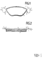
- Fig. 1
- die Vorderansicht eines erfindungsgemäßen Bremsklotzes und
- Fig. 2
- die Draufsicht auf einen Bremsklotz nach Fig. 1.
- Fig. 1
- the front view of a brake pad according to the invention and
- Fig. 2
- the top view of a brake pad of FIG. 1st
Der Bremsklotz 1 besitzt eine Trägerplatte 5, auf der ein Belag 2 aufgebracht ist. An den beiden Seiten der Trägerplatte 5 geht diese in zwei hammerförmige Ansätze 3,4 über, die zum Abstützen des Bremsklotzes an einem bzw. zwei Trägerarmen dienen. Dabei können die Kanten 8,9,10 auf der rechten Seite bzw. 11,12,13 auf der linken Seite der Trägerplatte als auf Zug bzw. auf Druck beaufschlagte Seitenflächen dienen. Wichtig ist aber, daß alle Kanten in einer Ebene liegen, da die gesamten Seitenbereiche 3 bzw. 4 parallel zu dem restlichen Teil der Trägerplatte 5 um einen Betrag a versetzt sind, so daß auch bei abgeschliffenen Belägen immer die gesamte zur Abstützung dienende Fläche zur Verfügung steht.The
Claims (2)
- A brake shoe for disc brakes, comprising a carrier plate (5) and a friction lining (2) secured to the carrier plate (5), with two lateral areas (3, 4) of the carrier plate (5) on which no lining material is applied and which, at their narrow sides, have abutment surfaces (9, 10, 11, 12) or (8, 13), respectively, which show to the brake shoe and are averted therefrom and which are intended to support the brake shoe in the disc brake and cooperate with said in such a manner that at least in the presence of great brake application forces the circumferential force occurring at the brake shoe is transmitted via both lateral areas (3, 4) onto the disc brake,
characterised in that the entire lateral area (3, 4) serving to support the brake shoe is offset in parallel in relation to the remaining part of the carrier plate (5) in the direction moving away from the friction surface. - A brake shoe as claimed in claim 1,
characterised in that the offset lateral areas are formed by two attachments which substantially are of hook-shaped, in particular hammer-shaped configuration.
Applications Claiming Priority (2)
| Application Number | Priority Date | Filing Date | Title |
|---|---|---|---|
| DE19904002863 DE4002863A1 (en) | 1990-02-01 | 1990-02-01 | BRAKE PAD |
| DE4002863 | 1990-02-01 |
Publications (2)
| Publication Number | Publication Date |
|---|---|
| EP0442048A1 EP0442048A1 (en) | 1991-08-21 |
| EP0442048B1 true EP0442048B1 (en) | 1994-03-23 |
Family
ID=6399154
Family Applications (1)
| Application Number | Title | Priority Date | Filing Date |
|---|---|---|---|
| EP19900121944 Revoked EP0442048B1 (en) | 1990-02-01 | 1990-11-16 | Brake pad |
Country Status (4)
| Country | Link |
|---|---|
| EP (1) | EP0442048B1 (en) |
| DE (2) | DE4002863A1 (en) |
| DK (1) | DK0442048T3 (en) |
| ES (1) | ES2050336T3 (en) |
Cited By (1)
| Publication number | Priority date | Publication date | Assignee | Title |
|---|---|---|---|---|
| EP1217247A2 (en) | 2000-12-22 | 2002-06-26 | Continental Teves AG & Co. oHG | Brake pad for a partially lined disc brake |
Families Citing this family (5)
| Publication number | Priority date | Publication date | Assignee | Title |
|---|---|---|---|---|
| DE4127113A1 (en) * | 1991-08-16 | 1993-02-18 | Teves Gmbh Alfred | Disc brake shoe - has support plate to which lining is sintered |
| DE4318749A1 (en) * | 1993-06-05 | 1994-12-08 | Teves Gmbh Alfred | Brake lining for disc brakes |
| DE4334840A1 (en) * | 1993-10-13 | 1995-04-20 | Teves Gmbh Alfred | Brake pads for disc brakes |
| DE4430955A1 (en) * | 1994-08-31 | 1996-03-07 | Teves Gmbh Alfred | Disc brake pad design |
| DE10215425A1 (en) * | 2002-04-08 | 2003-10-23 | Continental Teves Ag & Co Ohg | Brake lining for friction brake esp. motor vehicle disc brakes has lining support consisting of one part of one material, and second part of second material of lower density, containing light metal, for weight reduction |
Family Cites Families (9)
| Publication number | Priority date | Publication date | Assignee | Title |
|---|---|---|---|---|
| US3349871A (en) * | 1965-07-08 | 1967-10-31 | Dayton Steel Foundry Co | Brake pad structure |
| US3767018A (en) * | 1971-01-21 | 1973-10-23 | Milford Rivet And Machine Co | Brake shoe and method of manufacture thereof |
| US3762509A (en) * | 1971-07-02 | 1973-10-02 | Ford Motor Co | Brake shoe construction for a motor vehicle disc brake |
| JPS52135969A (en) * | 1976-05-11 | 1977-11-14 | Akebono Brake Ind Co Ltd | Friction pad of disc brake |
| DE7803310U1 (en) * | 1978-02-04 | 1981-06-11 | Alfred Teves Gmbh, 6000 Frankfurt | BRAKE SHOE FOR A PARTAL DISC BRAKE, ESPECIALLY FOR MOTOR VEHICLES |
| DE2854344A1 (en) * | 1978-12-15 | 1980-06-26 | Knorr Bremse Gmbh | BRAKE PAD GUIDE ON DISC BRAKES |
| DE3049818A1 (en) * | 1979-08-20 | 1982-02-25 | Tokico Ltd | FRICTION PAD GUIDE DEVICE FOR DISC BRAKE |
| JPS6021564Y2 (en) * | 1979-08-20 | 1985-06-27 | トキコ株式会社 | Disc brake friction pad guide device |
| EP0341610B1 (en) * | 1988-05-07 | 1994-01-19 | ITT Automotive Europe GmbH | Spot-type disc brake |
-
1990
- 1990-02-01 DE DE19904002863 patent/DE4002863A1/en not_active Ceased
- 1990-11-16 EP EP19900121944 patent/EP0442048B1/en not_active Revoked
- 1990-11-16 DK DK90121944T patent/DK0442048T3/en active
- 1990-11-16 ES ES90121944T patent/ES2050336T3/en not_active Expired - Lifetime
- 1990-11-16 DE DE90121944T patent/DE59005116D1/en not_active Revoked
Cited By (3)
| Publication number | Priority date | Publication date | Assignee | Title |
|---|---|---|---|---|
| EP1217247A2 (en) | 2000-12-22 | 2002-06-26 | Continental Teves AG & Co. oHG | Brake pad for a partially lined disc brake |
| DE10064168A1 (en) * | 2000-12-22 | 2002-07-04 | Continental Teves Ag & Co Ohg | Brake pad for a partial brake disc brake |
| DE10064168B4 (en) | 2000-12-22 | 2023-06-15 | Continental Automotive Technologies GmbH | Brake lining for a spot-type disc brake |
Also Published As
| Publication number | Publication date |
|---|---|
| DE59005116D1 (en) | 1994-04-28 |
| DE4002863A1 (en) | 1991-08-08 |
| DK0442048T3 (en) | 1994-05-02 |
| ES2050336T3 (en) | 1994-05-16 |
| EP0442048A1 (en) | 1991-08-21 |
Similar Documents
| Publication | Publication Date | Title |
|---|---|---|
| EP0524178B1 (en) | Brake pad with chamfered lining | |
| DE4028951A1 (en) | DISC BRAKE DEVICE | |
| EP0442048B1 (en) | Brake pad | |
| DE2230949C3 (en) | Brake shoe guide for a partially lined disc brake | |
| DE4337854C2 (en) | Split bicycle brake shoe block of different compositions on the braking surface for simultaneous contact with the rim | |
| DE2513131A1 (en) | BRAKE SHOE FOR DISC BRAKES | |
| DE10305094A1 (en) | Bicycle brake assembly with interchangeable brake pads | |
| DE3518540A1 (en) | SEAT COUPLING | |
| DE4215198A1 (en) | Wear indicator for disc brakes | |
| DE2408075A1 (en) | DISC BRAKE | |
| DE102017101525B4 (en) | Brake shoe and brake device | |
| DE4335001C2 (en) | Brake pads for disc brakes | |
| DE102009034858A1 (en) | Brake pad for a disc brake | |
| DE2901349A1 (en) | CRUSH-PROOF BRAKE DISC FOR VEHICLE BRAKES | |
| DE3402530A1 (en) | DRUM BRAKE | |
| DE2248143B2 (en) | Brake shoe suspension for disc brakes | |
| DE19880564B4 (en) | Friction lining bearing disc for a mechanical clutch | |
| DE69201601T2 (en) | Friction force transmission device for use in vacuum. | |
| DE650789C (en) | Flexible disc for friction clutches, in particular for motor vehicles | |
| DE3347387C2 (en) | Floating caliper disc brake | |
| DE20112593U1 (en) | Travel limiter for automotive shock absorbers | |
| EP0601986B1 (en) | Air deposition chamber | |
| EP0189490B1 (en) | Brake for the gripper shuttle of a loom | |
| DE10392238T5 (en) | torsion plate | |
| DE862618C (en) | Braking device for rail vehicles |
Legal Events
| Date | Code | Title | Description |
|---|---|---|---|
| PUAI | Public reference made under article 153(3) epc to a published international application that has entered the european phase |
Free format text: ORIGINAL CODE: 0009012 |
|
| 17P | Request for examination filed |
Effective date: 19901116 |
|
| AK | Designated contracting states |
Kind code of ref document: A1 Designated state(s): DE DK ES FR GB IT NL |
|
| 17Q | First examination report despatched |
Effective date: 19920827 |
|
| ITF | It: translation for a ep patent filed | ||
| RAP1 | Party data changed (applicant data changed or rights of an application transferred) |
Owner name: ITT AUTOMOTIVE EUROPE GMBH |
|
| GRAA | (expected) grant |
Free format text: ORIGINAL CODE: 0009210 |
|
| AK | Designated contracting states |
Kind code of ref document: B1 Designated state(s): DE DK ES FR GB IT NL |
|
| GBT | Gb: translation of ep patent filed (gb section 77(6)(a)/1977) |
Effective date: 19940328 |
|
| REF | Corresponds to: |
Ref document number: 59005116 Country of ref document: DE Date of ref document: 19940428 |
|
| REG | Reference to a national code |
Ref country code: DK Ref legal event code: T3 |
|
| REG | Reference to a national code |
Ref country code: ES Ref legal event code: FG2A Ref document number: 2050336 Country of ref document: ES Kind code of ref document: T3 |
|
| ET | Fr: translation filed | ||
| PLBI | Opposition filed |
Free format text: ORIGINAL CODE: 0009260 |
|
| 26 | Opposition filed |
Opponent name: LUCAS INDUSTRIES PUBLIC LIMITED COMPANY Effective date: 19941223 |
|
| NLR1 | Nl: opposition has been filed with the epo |
Opponent name: LUCAS INDUSTRIES PUBLIC LIMITED COMPANY |
|
| PLBO | Opposition rejected |
Free format text: ORIGINAL CODE: EPIDOS REJO |
|
| APAC | Appeal dossier modified |
Free format text: ORIGINAL CODE: EPIDOS NOAPO |
|
| APAE | Appeal reference modified |
Free format text: ORIGINAL CODE: EPIDOS REFNO |
|
| APCC | Communication from the board of appeal sent |
Free format text: ORIGINAL CODE: EPIDOS OBAPO |
|
| APCC | Communication from the board of appeal sent |
Free format text: ORIGINAL CODE: EPIDOS OBAPO |
|
| APCC | Communication from the board of appeal sent |
Free format text: ORIGINAL CODE: EPIDOS OBAPO |
|
| APCC | Communication from the board of appeal sent |
Free format text: ORIGINAL CODE: EPIDOS OBAPO |
|
| PGFP | Annual fee paid to national office [announced via postgrant information from national office to epo] |
Ref country code: GB Payment date: 19991020 Year of fee payment: 10 |
|
| PGFP | Annual fee paid to national office [announced via postgrant information from national office to epo] |
Ref country code: ES Payment date: 19991112 Year of fee payment: 10 |
|
| PGFP | Annual fee paid to national office [announced via postgrant information from national office to epo] |
Ref country code: FR Payment date: 19991117 Year of fee payment: 10 |
|
| PGFP | Annual fee paid to national office [announced via postgrant information from national office to epo] |
Ref country code: DK Payment date: 19991118 Year of fee payment: 10 |
|
| PGFP | Annual fee paid to national office [announced via postgrant information from national office to epo] |
Ref country code: DE Payment date: 19991127 Year of fee payment: 10 |
|
| PGFP | Annual fee paid to national office [announced via postgrant information from national office to epo] |
Ref country code: NL Payment date: 19991130 Year of fee payment: 10 |
|
| RAP2 | Party data changed (patent owner data changed or rights of a patent transferred) |
Owner name: CONTINENTAL TEVES AG & CO. OHG |
|
| NLT2 | Nl: modifications (of names), taken from the european patent patent bulletin |
Owner name: CONTINENTAL TEVES AG & CO. OHG |
|
| PLAB | Opposition data, opponent's data or that of the opponent's representative modified |
Free format text: ORIGINAL CODE: 0009299OPPO |
|
| R26 | Opposition filed (corrected) |
Opponent name: LUCAS INDUSTRIES LIMITED Effective date: 19941223 |
|
| APAC | Appeal dossier modified |
Free format text: ORIGINAL CODE: EPIDOS NOAPO |
|
| RDAH | Patent revoked |
Free format text: ORIGINAL CODE: EPIDOS REVO |
|
| NLR1 | Nl: opposition has been filed with the epo |
Opponent name: LUCAS INDUSTRIES LIMITED |
|
| RDAG | Patent revoked |
Free format text: ORIGINAL CODE: 0009271 |
|
| STAA | Information on the status of an ep patent application or granted ep patent |
Free format text: STATUS: PATENT REVOKED |
|
| 27W | Patent revoked |
Effective date: 20000729 |
|
| GBPR | Gb: patent revoked under art. 102 of the ep convention designating the uk as contracting state |
Free format text: 20000729 |
|
| NLR2 | Nl: decision of opposition | ||
| APAH | Appeal reference modified |
Free format text: ORIGINAL CODE: EPIDOSCREFNO |