EP0442058A2 - Pulvérisateur de liquides - Google Patents
Pulvérisateur de liquides Download PDFInfo
- Publication number
- EP0442058A2 EP0442058A2 EP90122820A EP90122820A EP0442058A2 EP 0442058 A2 EP0442058 A2 EP 0442058A2 EP 90122820 A EP90122820 A EP 90122820A EP 90122820 A EP90122820 A EP 90122820A EP 0442058 A2 EP0442058 A2 EP 0442058A2
- Authority
- EP
- European Patent Office
- Prior art keywords
- spray device
- particular according
- liquid
- liquid spray
- air pump
- Prior art date
- Legal status (The legal status is an assumption and is not a legal conclusion. Google has not performed a legal analysis and makes no representation as to the accuracy of the status listed.)
- Granted
Links
Images


Classifications
-
- B—PERFORMING OPERATIONS; TRANSPORTING
- B05—SPRAYING OR ATOMISING IN GENERAL; APPLYING FLUENT MATERIALS TO SURFACES, IN GENERAL
- B05B—SPRAYING APPARATUS; ATOMISING APPARATUS; NOZZLES
- B05B7/00—Spraying apparatus for discharge of liquids or other fluent materials from two or more sources, e.g. of liquid and air, of powder and gas
- B05B7/24—Spraying apparatus for discharge of liquids or other fluent materials from two or more sources, e.g. of liquid and air, of powder and gas with means, e.g. a container, for supplying liquid or other fluent material to a discharge device
- B05B7/2402—Apparatus to be carried on or by a person, e.g. by hand; Apparatus comprising containers fixed to the discharge device
- B05B7/2405—Apparatus to be carried on or by a person, e.g. by hand; Apparatus comprising containers fixed to the discharge device using an atomising fluid as carrying fluid for feeding, e.g. by suction or pressure, a carried liquid from the container to the nozzle
- B05B7/2424—Apparatus to be carried on or by a person, e.g. by hand; Apparatus comprising containers fixed to the discharge device using an atomising fluid as carrying fluid for feeding, e.g. by suction or pressure, a carried liquid from the container to the nozzle the carried liquid and the main stream of atomising fluid being brought together downstream of the container before discharge
- B05B7/2427—Apparatus to be carried on or by a person, e.g. by hand; Apparatus comprising containers fixed to the discharge device using an atomising fluid as carrying fluid for feeding, e.g. by suction or pressure, a carried liquid from the container to the nozzle the carried liquid and the main stream of atomising fluid being brought together downstream of the container before discharge and a secondary stream of atomising fluid being brought together in the container or putting the carried liquid under pressure in the container
-
- B—PERFORMING OPERATIONS; TRANSPORTING
- B05—SPRAYING OR ATOMISING IN GENERAL; APPLYING FLUENT MATERIALS TO SURFACES, IN GENERAL
- B05B—SPRAYING APPARATUS; ATOMISING APPARATUS; NOZZLES
- B05B11/00—Single-unit hand-held apparatus in which flow of contents is produced by the muscular force of the operator at the moment of use
- B05B11/01—Single-unit hand-held apparatus in which flow of contents is produced by the muscular force of the operator at the moment of use characterised by the means producing the flow
- B05B11/06—Gas or vapour producing the flow, e.g. from a compressible bulb or air pump
Definitions
- the invention relates to a liquid spray device according to the preamble of patent claim 1.
- a liquid spray device of this type is known from US-PS 4 167 941.
- the air pump is operated there via a handle on the head piece side.
- the overpressure cushion that builds up is available as a storage force.
- the liquid is squeezed out by actuating a discharge valve on the head piece side.
- the storage device consists of a chamber with a piston disk guided freely therein, which rests on a compression spring which correspondingly tightens with increasing filling of the respective chamber.
- the overpressure cushion is built up via several small pistons using a rotary movement of the said handle.
- the pistons which are arranged radially and in opposite directions transversely to the longitudinal center axis of the liquid spraying device, engage with their piston shaft via a control pin in a zigzag-shaped link slot which, taking into account the rotatability of the dispenser head, follows an undulating circular path. That requires a lot of "shooting".
- the object of the present invention is to manufacture a generic liquid spray device simple, advantageous to use in such a way that a strong, so-called “dry” spray jet is achieved without storage requiring springs.
- a liquid spray device of the generic type is realized, which is characterized by a simple structure and perfect function. Without a special spring body, while maintaining the usual volume share for the actual dispenser mechanism, a stable spray jet profile is achieved, so that even the most varied of media can be applied, so that even the more environmentally friendly cartridge system can be used with advantage. All this is achieved by a cartridge receiving space that can be placed between the removable head piece and an air pump handle located at the opposite end under the air pressure. The operating medium can thus be stored in columns and rooms that are already present, even taking into account the space accommodating the cartridge. In addition, there is the head area, i.e. in the space available from the head piece.
- the unit that creates the corresponding overpressure air cushion sits in the end conveniently remote from the head piece.
- the latter therefore remains easily removable for the insertion of the next, full cartridge or the removal of the empty cartridge.
- a plug connection nipple arranged on the head piece projects into the cartridge receiving space, through which the inside of the cartridge is connected to the air pressure. This results in a balanced distribution of the overpressure air cushion, one part causing the liquid to be lifted or brought in and the other part ensuring surprisingly good atomization.
- the plug-in connection nipple has a liquid lock.
- liquid itself is thus prevented from unintentionally escaping into the surrounding overpressure cushion, whereas the air itself reaches the interior of the cartridge via the plug-in connection nipple.
- a liquid barrier is achieved with simple means in that the liquid barrier is formed by an annular membrane of the plug-in connection nipple, which rests with its lip edge sealingly on the jacket wall of a riser pipe conducting the liquid into the head piece.
- the corresponding lip rim in combination with enough flexible material of such a plug-in nipple looks extremely sensitive; separate formations of such a membrane are therefore not required.
- the air pump handle is designed as a rotating sleeve which guides itself on the housing of the liquid spraying device and is connected to an air pump piston which runs in a cylinder chamber located in the housing.
- the outer shape of the housing is advantageously used here as a guide means for the rotating sleeve and the inner area for the assignment and design of the cylinder chamber.
- an advantageous embodiment is achieved by controlling the linkage of the piston / air pump handle functional unit. It is also proposed that the cylinder chamber of a retraction of the housing is formed and the means of the link control are accommodated in the remaining storage room.
- the grooves are assigned essentially axial insertion shafts, which in the assembled state are blocked by a steeply sloping back comb of the one link part. This leads to a correct allocation of the means bringing the superimposing axial / rotary stroke of the piston.
- an advantageous embodiment is achieved by a flatter course of the rising grooves in the final phase of the pumping movement, which also form support pockets for the guide pins in both ends.
- the support pockets define the end positions, so that an angle of inclination for the grooves is applicable, which is far outside the self-locking.
- the finite limitation of the grooves lies on a working stroke of approx.
- the invention proposes that the air pump piston carries a piston sleeve with an end annular space.
- Such an annular space expediently lies in the edge area of the sleeve, thus leading on the one hand to the highly elastic or flexible sleeve lip typical of the sleeve and on the other hand to a stable transition to the remaining central area of the sleeve designed as a pot or plate.
- the piston sleeve assumes an additional function insofar as it also forms the valve flap of an inlet valve of the cylinder chamber and a cap screwed to the air pump handle is clipped onto the pot-shaped end drawn in on the housing side. In this way, the piston continues as the inner leg of a rotationally symmetrical U-profile of the handle, which surrounds the lower end of the housing.
- the plug connection nipple of a perforated holding plate is formed centrally, which is framed between the upper end of the housing and the screw-connected head piece and continues into a counter-nipple plug-connected to the head piece.
- the counter nipple is used in the head area to form a rotationally symmetrical Y-channel, the Y-web of which leads to the dispensing valve and the outer Y-leg connects via a transverse channel to a headpiece chamber which is located above the cartridge - Recording room extends.
- the centering effect of the plug connection nipple leaves a uniform annular space between the jacket wall of the cartridge and the inner wall of the housing.
- the outlet valve can be actuated by a spray head pushbutton which is spring-loaded in the direction of the closed basic position.
- there is still a favorable embodiment through an end annular space of the piston sleeve as a pump limiter.
- the dispenser Sp containing the liquid spray device according to the invention is designed as an elongated, essentially cylindrical free-standing device, consisting of a housing 1, a removable head piece 2 and a handle 3. The latter serves to actuate an air pump P.
- the air pump handle 3 sits at the end of the housing 1 opposite the head piece 2.
- the air pump P While the handle 3 rotates back and forth, the air pump P generates an overpressure cushion in the interior of the dispenser. This actuates an outlet valve 4 on the head piece side of the outlet of a liquid 5 contained in the dispenser by this overpressure air cushion both loading the mirror 6 of the liquid 5 and atomizing it by mixing with the liquid jet.
- the liquid jet emerges from a so-called nozzle 7 of a corresponding spray device 8.
- the added air component leads to a dimensionally stable, so-called "dry" spray jet.
- the overpressure cushion building up in the dispenser Sp is generated in a cylinder chamber 9 of the air pump P. From there the compressed air arrives in a pressure pre-chamber 10. From here the distribution takes place in the section of the housing 1 which holds the liquid 5 containing cartridge K is used. It is interchangeably assigned to the donor Sp. It has a diameter such that the cartridge-receiving space 11 leaves an evading annular gap 12 on the jacket wall side, so that compressed air connection is provided up to the head piece 2, that is to say to the spray device 8.
- the cartridge K is designed in the form of a bottle and consequently merges into a neck 14 at its end facing away from the edge-reinforced base 13.
- the neck 14 arises from the axially approximately drawn-in cover 15 of the cartridge K and has a cylindrical mouth 16.
- the free space of the housing 1 around the neck 14 and also axially above it ends with a holding plate 17. It is perforated. These are openings 18, one of which can be seen in FIG. 1. Via the latter (18), the compressed air gains connection to the dome-shaped interior of the head piece 2, more precisely that Head chamber 2 '. From here, the branching or division takes place in the sense explained above.
- connection on the cartridge side is formed by a plug-in connection nipple 19 starting from the holding plate 17 and indirectly connected to the head piece 2. It overlaps into the cylindrical mouth 16 of the neck 14. So there is a kind of pipe coupling.
- the lower outer edge of the plug connection nipple 19 has a sealing bead 20. Via the plug connection nipple 19, the interior 21 of the cartridge K is connected to the excess air pressure.
- the liquid 5 is prevented from escaping through the mouth 16 of the neck 14 into the cartridge receiving space 11, for example in cases in which the dispenser Sp is used for spraying in an upside-down position.
- the plug-in connection nipple 19 has a liquid barrier that only allows the passage of air.
- it is a relatively thin-walled ring membrane 22. The latter, with its lip edge, which may be tapering, lies sealingly and only yields to the air pressure on the jacket wall of a riser pipe 23 which conducts the liquid 5 into the head piece 2.
- the riser pipe 23 starts from the removable head piece 2. It extends in the longitudinal central axis x-x of the dispenser Sp and extends to the bottom 13 of the cartridge K, but leaving a small distance from it (13), so that the liquid can enter the lower end of the riser pipe 23 unhindered.
- the other, upper end of the riser pipe 23 is on a central, downward, into the mouth 14 protruding nozzle 24, which is coaxial to a spring chamber 25 arranged above it, the wall forming an upwardly open pot continues over a pot edge into a bush part 26 open in the opposite direction, which, concentrically and at a distance from the spring chamber 25, extends one of the Top of the holding plate 17 receives outgoing nipples.
- the latter leaves between its jacket wall and the inner wall of the bushing part 26 an annular channel 28 which is connected to the overpressure air cushion via one or more openings 29.
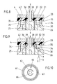
- the edge serving as a cross connection between the wall of the spring chamber 25 and the bush part 26 has openings 30. This also clears the way to the closing outlet valve 4 (cf. FIG. 9).
- the outlet valve 4 consisting of a horizontally embedded annular disk 31 made of elastic material rests on annular walls 32 and 33 arranged concentrically to the longitudinal central axis xx.
- the inner annular wall 33 forming the spring chamber 25 has transverse channels 34. The latter form the connection between the spring chamber and a circumferential cavity 35 below the washer 31 ago.
- a further component of the outlet valve 4 is a central stem 36.
- This has an annular groove 37 at the level of the annular disc 31.
- At the bottom of the annular groove there is at least one branch duct 38. The latter connects the liquid and air-penetrated annular space section of the spring chamber 25 to a central outlet duct 39 which is connected directly to the transversely outgoing nozzle 7.
- the lower end of the mentioned shaft 36 extends into the spring chamber 25 and supports the upper end turn of the compression spring 40 loading the outlet valve in the direction of the closed position.
- the other end turn rests on an annular shoulder between the connecting piece 24 and the wall circumscribing the annular chamber 25.
- the outlet valve 4 is actuated via a free-standing spray head pushbutton 41 of the head piece 2 which is spring-loaded in the direction of the closed basic position.
- the upper-side boundary system for the annular disk 31 forms a hat-shaped plug-in part 42, which is held in an annular groove of a cylindrical recess 43 of the head piece 2 and guides the shaft 36 above the annular disk 31.
- the holding plate 17 which brings the plug connection via plug connection nipple 19 to the cartridge K is framed peripherally between the upper end edge 1 'of the housing 1 and the head piece 2 connected to it by screws.
- a centering projection 44 which, despite the elasticity of the material used, since this must also form the membrane 22, gives the edge section and the entire component a high degree of internal stability.
- a bell-shaped edge 45 with a corresponding internal thread is formed on the rotationally symmetrical head piece 2, which engages in the corresponding external thread of the housing 1.
- the described channel situation in the dispenser head leads to the counter nipple 27 in the head piece 2 being used to form a rotationally symmetrical Y channel, the Y web a of which points to the outlet valve 4, the outer Y leg b via the opening 30 to the head piece.
- the air pump handle 3 is designed as a rotating sleeve which is guided on the housing 1 of the liquid spraying device and which is connected to an air pump piston 46.
- the lower section of the housing 1 merges into a recess 47 which is clearly recognizable from the drawing.
- the offset space 48 remaining through the indentation 47 accommodates the means of a link control that displaces the piston 46.
- the offset space 48 means the space which extends between the cylindrical jacket wall of the recess 47 and the likewise cylindrical inner wall of the handle 3 guided on the housing 1. The slim shape of the dispenser is retained.
- the link control is formed by two helically rising, raidal inward directed open grooves 49. These are located on the inside of the air pump handle 3. They are assigned in a non-overlapping manner and each work with a fixed, radially outwardly directed guide pin 50 of the housing 1 respectively his confiscation 47 together.
- each of the two guide pins 50 arranged in a diametrically opposed position each carry a roller 51.
- the latter can be attached loosely be, since the axially extending inner wall of the handle 3 has a locking effect.
- the same essentially axially aligned insertion shafts 52 are assigned, which in the assembled state, as can be seen from the development in FIG. 7, can be closed with a steeply falling back comb 53.
- the curve of the two grooves 49 is chosen so that d.
- H. the compression the flatter rising section comes to control.
- Support pockets 54 left in the ends of the grooves 49 result in a certain locking or locking effect, so that self-adjustment of the handle 3, for example due to accidental touches etc. in the utensil pocket, is counteracted.
- a pump valve 56 is located on the cartridge side. It consists of a cut-out valve flap which is in a socket is let in and covers the centrally located valve opening 57 in the transverse wall 55 from above.
- the shoulder Sch adjoining the pressure pre-chamber 10 has support ribs 59 formed on the top side, so that between the surface-stable bottom 13 of the cartridge K and the offset housing inner profile passages 60 remain. As a result, the upper edges of the support ribs 59 form the actual annular cartridge shelf in the housing 1.
- the piston 46 of the air pump P carries a piston sleeve 61. It is a hat-shaped body made of elastic material such as rubber or the like. In this respect, it is also suitable for performing a double function which consists in the piston sleeve 61 simultaneously forming the valve flap 62 of an inlet valve 63 of the pump P seated on the piston 46.
- the piston sleeve 61 is clipped onto the end of a cap 64 which is screwed to the air pump handle 3 and is also cup-shaped and drawn in on the housing side.
- the fastening-side end of the piston 46 forms a corresponding mushroom head which is gripped behind by an edge bead 61 'on the inner edge of the cup-shaped sleeve.
- valve flap 62 The zone forming the actual valve flap 62 and also the further horizontal environment lie flat on the flat underside of the pot base or, better said, the top 65 of the pot-like retraction. In the center of this blanket, which is denoted by 65, there is also a valve opening 66. In the pushed-in end position of the piston 46, the flat top of the sleeve lies flush with the underside of the transverse wall 55, leaving the light gap shown in FIG. 1.
- a further embodiment of the piston sleeve consists in creating an annular space 67 on the end face.
- the latter has a V-shaped cross section, but can also be a trapezoidal cross section.
- the V-opening points in the direction of the flat transverse wall 55.
- the purpose of the peripheral notch is on the one hand to create the cuff-like piston lip, which is undercut, and on the other hand also the creation of a pump limiter. If the pressure in the cartridge receiving space is identical to the pressure in the annular space 67 of the piston 46, further inflation of the cartridge receiving space 11 is no longer possible. In the end of pressure position, the pump piston closes off the overflow opening to the cartridge receiving chamber 11 and leaves a compression clearance in this position.
- the housing 1 In order to create or renew or supplement the overpressure cushion required for dispensing the liquid 5, the housing 1 is gripped with one hand; with the other hand, the operator performs reciprocating rotary movements on the handle 3.
- the gate control leads to a superimposed rotary and axial stroke movement of the piston 46.
- the overpressure thus generated is distributed starting from the pressure pre-chamber 10 such that the liquid 5 in the cartridge K is under pressure and compressed air is also present in front of the outlet valve 4. If this is brought into the open position according to FIG. 9, then both components, air plus liquid, enter the outlet channel 39 via the branch channel 38, passing the nozzle 7 with further mixing and forming the desired dimensionally stable jet.
- the compressed air passes through the ring membrane 22, which acts like a lock, but which in turn does not allow any liquid to get into the remaining head chamber 2 'when the dispenser is in a tilted position.
- the overpressure rises the elastic counter nipple 27 from the corresponding inner wall of the socket part 26.
- the spray jet can be interrupted as soon as the spray device 8 or the spray head pushbutton 41 is released, which, due to the restoring force of the spring 40, returns to its closed starting position.
- the scenery parts circumscribing the groove can be created as individual pieces or at least one of the two parts of the handle 3 can be molded in the same way. In the exemplary embodiment, this is the upper part I.
- the lower part II is therefore fastened in the classic manner. All individual parts can be injection molded from plastic; only the compression spring 40 is made of stainless steel.
- the container section of the cartridge K can be designed as a sack, but the cover 15, also having the neck shape described, is designed as a hard part which is connected to the edge of the sack.
- the bag bottom is also stiffened so that the passages 60 do not become clogged.
Landscapes
- Nozzles (AREA)
- Containers And Packaging Bodies Having A Special Means To Remove Contents (AREA)
Applications Claiming Priority (2)
| Application Number | Priority Date | Filing Date | Title |
|---|---|---|---|
| DE4004653 | 1990-02-15 | ||
| DE4004653A DE4004653A1 (de) | 1990-02-15 | 1990-02-15 | Fluessigkeitsspruehvorrichtung |
Publications (3)
| Publication Number | Publication Date |
|---|---|
| EP0442058A2 true EP0442058A2 (fr) | 1991-08-21 |
| EP0442058A3 EP0442058A3 (en) | 1992-02-19 |
| EP0442058B1 EP0442058B1 (fr) | 1995-01-11 |
Family
ID=6400188
Family Applications (1)
| Application Number | Title | Priority Date | Filing Date |
|---|---|---|---|
| EP90122820A Expired - Lifetime EP0442058B1 (fr) | 1990-02-15 | 1990-11-29 | Pulvérisateur de liquides |
Country Status (7)
| Country | Link |
|---|---|
| US (1) | US5405060A (fr) |
| EP (1) | EP0442058B1 (fr) |
| AT (1) | ATE116872T1 (fr) |
| DE (2) | DE4004653A1 (fr) |
| DK (1) | DK0442058T3 (fr) |
| ES (1) | ES2066942T3 (fr) |
| GR (1) | GR3015745T3 (fr) |
Cited By (4)
| Publication number | Priority date | Publication date | Assignee | Title |
|---|---|---|---|---|
| US5411183A (en) * | 1992-12-17 | 1995-05-02 | Wella Aktiengesellschaft | Liquid spray or foam dispensing apparatus |
| CN103826515A (zh) * | 2011-09-17 | 2014-05-28 | 亨利佩特里管理有限责任公司 | 皂泵 |
| CN106622750A (zh) * | 2007-02-06 | 2017-05-10 | 替代包装解决方案公司 | 单圈旋转致动的持续喷雾泵机构 |
| WO2018077320A1 (fr) * | 2016-10-26 | 2018-05-03 | Wik Elektrogeräte Entwicklungs- Und Service-Gmbh & Co. Kg | Appareil de mise en forme des cheveux pour appliquer un additif au moyen d'air comprimé |
Families Citing this family (13)
| Publication number | Priority date | Publication date | Assignee | Title |
|---|---|---|---|---|
| DE4108428A1 (de) * | 1991-03-15 | 1992-09-17 | Wiegner Georg Dipl Kaufm | Vorrichtung zur dosierten abgabe von unter druck stehenden inhaltstoffen |
| DE4136826A1 (de) * | 1991-11-08 | 1993-05-13 | Pfeiffer Erich Gmbh & Co Kg | Austragvorrichtung fuer medien |
| US6991136B2 (en) * | 2001-11-26 | 2006-01-31 | De La Guardia Mario Felix | Pressurizing device for attachment to fluid containers |
| US20040164083A1 (en) * | 2003-02-26 | 2004-08-26 | Lin Arlo H. T. | Bag for use in gas can |
| KR100782330B1 (ko) * | 2006-07-14 | 2007-12-06 | 주식회사 예찬 | 용기 출몰식 펌프디스펜서 |
| GB2493352A (en) * | 2011-08-01 | 2013-02-06 | Owen Brown | A sprayer comprising a detachable product module and an air pressurisation apparatus. |
| US9415401B2 (en) | 2012-04-04 | 2016-08-16 | Alternative Packaging Solutions Llc | One turn actuated duration spray pump mechanism |
| US8908896B2 (en) * | 2012-06-29 | 2014-12-09 | Intel Corporation | Earpiece for an electronic device |
| US20140183222A1 (en) * | 2012-10-19 | 2014-07-03 | Rust-Oleum Corporation | Propellantless Aerosol System |
| WO2015178917A1 (fr) * | 2014-05-22 | 2015-11-26 | Colgate-Palmolive Company | Cartouche de recharge, système comprenant la cartouche de recharge et distributeur à pompe |
| EP4263065B1 (fr) | 2020-12-15 | 2024-07-17 | Unilever IP Holdings B.V. | Pulvérisateur |
| AR125176A1 (es) | 2020-12-15 | 2023-06-21 | Unilever Global Ip Ltd | Dispensador de aerosol |
| WO2024054643A1 (fr) * | 2022-09-08 | 2024-03-14 | Mind 2 Make Inc. | Bombe aérosol manuellement rechargeable et réutilisable, et procédé |
Family Cites Families (30)
| Publication number | Priority date | Publication date | Assignee | Title |
|---|---|---|---|---|
| US337943A (en) * | 1886-03-16 | Clabence a | ||
| GB189507723A (en) * | 1895-04-17 | 1895-08-31 | Henry Bartz | An Improved Mustard Pot. |
| US1080835A (en) * | 1912-09-20 | 1913-12-09 | George J Kelley | Atomizer. |
| GB179740A (en) * | 1921-03-12 | 1922-05-18 | Charles Alfred Outwin Saxelby | Improvements relating to spraying apparatus |
| GB299280A (en) * | 1928-06-01 | 1928-10-25 | Walter Roy Weeks | Improvements in apparatus for spraying paint, varnish, lacquer or the like |
| US1967743A (en) * | 1933-05-05 | 1934-07-24 | Russell H Chaille | Dispenser |
| US2060512A (en) * | 1935-12-16 | 1936-11-10 | Herbert L Magill | Liquid dispensing device |
| US2608320A (en) * | 1947-03-31 | 1952-08-26 | Jr Joseph R Harrison | Pump type dispenser with cartridge having flexible and rigid portions |
| US2598869A (en) * | 1949-05-03 | 1952-06-03 | White James Adelbert | Pressure operated pipette filler |
| US2710711A (en) * | 1952-01-25 | 1955-06-14 | Hutton Dorothy Dear | Medicinal applicator |
| US3207387A (en) * | 1963-10-16 | 1965-09-21 | Brickman Robert | Portable sprayer |
| US3198405A (en) * | 1964-04-29 | 1965-08-03 | William C Pfeil | Dispenser |
| GB1379182A (en) * | 1971-06-10 | 1975-01-02 | Yoshino Kogyosho Co Ltd | Spraying device |
| US3955720A (en) * | 1972-11-15 | 1976-05-11 | Malone David C | Low pressure dispensing apparatus with air pump |
| FR2320788A2 (fr) * | 1975-08-14 | 1977-03-11 | Pulverisation Step Ste Tech | Perfectionnements apportes aux vaporisateurs |
| FR2342915A1 (fr) * | 1976-03-02 | 1977-09-30 | Henry Rene | Aerosol rechargeable |
| US3995779A (en) * | 1976-03-17 | 1976-12-07 | Lawrence Peska Associates, Inc. | Aerosol container |
| US4167941A (en) * | 1976-10-05 | 1979-09-18 | James D. Pauls, Ltd. (Limited Partnership) | Mechanically operated dispensing device for increasing discharge pressure and dispensing time |
| DE7631698U1 (de) * | 1976-10-09 | 1977-02-03 | Gebrueder Funke, 5768 Sundern | Vorrichtung zur entnahme von fluessigkeiten aus flaschen |
| US4147284A (en) * | 1977-05-25 | 1979-04-03 | Mizzi John V | Air propellant-aerosol dispenser and compressor |
| US4165025A (en) * | 1977-09-21 | 1979-08-21 | The Continental Group, Inc. | Propellantless aerosol with fluid pressure generating pump |
| US4235353A (en) * | 1978-03-24 | 1980-11-25 | James D. Pauls And J. Claybrook Lewis And Associates, Limited | Trigger operated dispensing device with accumulating chamber |
| US4341330A (en) * | 1978-10-06 | 1982-07-27 | The Continental Group, Inc. | Aerosol container |
| US4272228A (en) * | 1979-04-11 | 1981-06-09 | Security Plastics, Inc. | High volume dispensing pump |
| DE3022913A1 (de) * | 1980-06-19 | 1981-12-24 | Alfred Dipl.-Volksw. 8135 Söcking Becker | Zerstaeubereinrichtung |
| JPS6028529Y2 (ja) * | 1981-09-17 | 1985-08-29 | キヤニヨン株式会社 | 蓄圧タイプの噴霧器 |
| US4606477A (en) * | 1983-07-18 | 1986-08-19 | Tolco Corporation | Portable pressure sprayer |
| US4667856A (en) * | 1986-01-10 | 1987-05-26 | Nelson Marvin I | Dispenser for attachment to liquid containers |
| DE3742466C2 (de) * | 1987-12-15 | 1993-12-02 | Vorwerk Co Interholding | Mischeinrichtung in Sprühdosen zur Durchmischung feststoffhaltiger Suspensionen |
| DE3812935A1 (de) * | 1988-04-19 | 1989-11-02 | Oeco Tech Entwicklung & Vertri | Automatische spruehdose |
-
1990
- 1990-02-15 DE DE4004653A patent/DE4004653A1/de not_active Withdrawn
- 1990-11-29 DE DE59008258T patent/DE59008258D1/de not_active Expired - Fee Related
- 1990-11-29 ES ES90122820T patent/ES2066942T3/es not_active Expired - Lifetime
- 1990-11-29 DK DK90122820.5T patent/DK0442058T3/da active
- 1990-11-29 EP EP90122820A patent/EP0442058B1/fr not_active Expired - Lifetime
- 1990-11-29 AT AT90122820T patent/ATE116872T1/de not_active IP Right Cessation
-
1993
- 1993-08-03 US US08/101,798 patent/US5405060A/en not_active Expired - Fee Related
-
1995
- 1995-04-10 GR GR950400890T patent/GR3015745T3/el unknown
Cited By (6)
| Publication number | Priority date | Publication date | Assignee | Title |
|---|---|---|---|---|
| US5411183A (en) * | 1992-12-17 | 1995-05-02 | Wella Aktiengesellschaft | Liquid spray or foam dispensing apparatus |
| CN106622750A (zh) * | 2007-02-06 | 2017-05-10 | 替代包装解决方案公司 | 单圈旋转致动的持续喷雾泵机构 |
| CN106622750B (zh) * | 2007-02-06 | 2020-01-17 | 替代包装解决方案公司 | 单圈旋转致动的持续喷雾泵机构 |
| CN103826515A (zh) * | 2011-09-17 | 2014-05-28 | 亨利佩特里管理有限责任公司 | 皂泵 |
| US10758094B2 (en) | 2011-09-17 | 2020-09-01 | Henri Peteri Beheer B.V. | Soap pump |
| WO2018077320A1 (fr) * | 2016-10-26 | 2018-05-03 | Wik Elektrogeräte Entwicklungs- Und Service-Gmbh & Co. Kg | Appareil de mise en forme des cheveux pour appliquer un additif au moyen d'air comprimé |
Also Published As
| Publication number | Publication date |
|---|---|
| GR3015745T3 (en) | 1995-07-31 |
| DE59008258D1 (de) | 1995-03-02 |
| EP0442058A3 (en) | 1992-02-19 |
| EP0442058B1 (fr) | 1995-01-11 |
| ATE116872T1 (de) | 1995-01-15 |
| US5405060A (en) | 1995-04-11 |
| DE4004653A1 (de) | 1991-08-22 |
| ES2066942T3 (es) | 1995-03-16 |
| DK0442058T3 (da) | 1995-06-26 |
Similar Documents
| Publication | Publication Date | Title |
|---|---|---|
| EP0442058B1 (fr) | Pulvérisateur de liquides | |
| EP0738543B1 (fr) | Pompe de distribution en matière plastique pour matière pâteuse | |
| EP0492363B1 (fr) | Valve d'aspiration et/ou de refoulement pour une pompe de dosage ou de pulvérisation de produits liquides, à basse viscosité et pâteux | |
| DE4212413C2 (de) | Dosierpumpe aus Kunststoff für hochviskose, insbesondere pastenartige Medien | |
| EP0492354B1 (fr) | Pompe de dosage ou de pulvérisation pour délivrer des substances liquides, peu visqueuses ou pâteuses | |
| EP0084638B1 (fr) | Distributeur pour produits pâteux | |
| DE69106111T2 (de) | Handbetätigte Pumpe für Fluide. | |
| DE69506481T2 (de) | Vordruck-Handpumpe zur Zerstäuben einer Flüssigkeit und Abgabevorrichtung mit einer solchen Pumpe | |
| EP0338327A2 (fr) | Aérosol automatique | |
| DE69008512T2 (de) | Zerstäubungspumpe. | |
| WO2003026803A1 (fr) | Dispositif de dosage muni d'un systeme de pompage | |
| DE20304731U1 (de) | Dosierpumpe aus Kunststoff | |
| DE8907977U1 (de) | Gerät zum Versprühen von Flüssigkeiten | |
| DE69500443T2 (de) | Handbetätigte Pumpe mit Vordruckkammer zum Zerstäuben einer Flüssigkeit und Abgabevorrichtung mit einer solchen Pumpe | |
| EP0901836B1 (fr) | Distributeur de fluide | |
| EP3484628A1 (fr) | Distributeur pour matières liquides à pâteuses | |
| DE3421071A1 (de) | Von hand betaetigte abgabepumpe | |
| DE2837355A1 (de) | Kolben-handpumpe zur zerstaeubung von fluessigkeiten | |
| DE19739990A1 (de) | Spender für Medien | |
| EP1295645A1 (fr) | Dispositif de dosage muni d'une pompe | |
| DE10015968A1 (de) | Spender für Medien | |
| DE3001687B1 (de) | Verstellbare Duese an einem handbetaetigten Fluessigkeitszerstaeuber | |
| WO1990003849A1 (fr) | Pompe pour aerosol | |
| EP1514608B1 (fr) | Dispositif de dosage comprenant un actionneur élastique | |
| DE2749644A1 (de) | Zerstaeuberkopf mit zylinderkolbenanordnung fuer aersosole oder andere fluessigkeiten enthaltende behaelter |
Legal Events
| Date | Code | Title | Description |
|---|---|---|---|
| PUAI | Public reference made under article 153(3) epc to a published international application that has entered the european phase |
Free format text: ORIGINAL CODE: 0009012 |
|
| AK | Designated contracting states |
Kind code of ref document: A2 Designated state(s): AT BE CH DE DK ES FR GB GR IT LI LU NL SE |
|
| PUAL | Search report despatched |
Free format text: ORIGINAL CODE: 0009013 |
|
| AK | Designated contracting states |
Kind code of ref document: A3 Designated state(s): AT BE CH DE DK ES FR GB GR IT LI LU NL SE |
|
| 17P | Request for examination filed |
Effective date: 19920427 |
|
| 17Q | First examination report despatched |
Effective date: 19931028 |
|
| GRAA | (expected) grant |
Free format text: ORIGINAL CODE: 0009210 |
|
| AK | Designated contracting states |
Kind code of ref document: B1 Designated state(s): AT BE CH DE DK ES FR GB GR IT LI LU NL SE |
|
| PG25 | Lapsed in a contracting state [announced via postgrant information from national office to epo] |
Ref country code: GR Free format text: LAPSE BECAUSE OF FAILURE TO SUBMIT A TRANSLATION OF THE DESCRIPTION OR TO PAY THE FEE WITHIN THE PRESCRIBED TIME-LIMIT Effective date: 19950111 |
|
| REF | Corresponds to: |
Ref document number: 116872 Country of ref document: AT Date of ref document: 19950115 Kind code of ref document: T |
|
| ET | Fr: translation filed | ||
| REF | Corresponds to: |
Ref document number: 59008258 Country of ref document: DE Date of ref document: 19950302 |
|
| GBT | Gb: translation of ep patent filed (gb section 77(6)(a)/1977) |
Effective date: 19950214 |
|
| REG | Reference to a national code |
Ref country code: ES Ref legal event code: FG2A Ref document number: 2066942 Country of ref document: ES Kind code of ref document: T3 |
|
| ITF | It: translation for a ep patent filed | ||
| REG | Reference to a national code |
Ref country code: DK Ref legal event code: T3 |
|
| REG | Reference to a national code |
Ref country code: GR Ref legal event code: FG4A Free format text: 3015745 |
|
| PLBE | No opposition filed within time limit |
Free format text: ORIGINAL CODE: 0009261 |
|
| STAA | Information on the status of an ep patent application or granted ep patent |
Free format text: STATUS: NO OPPOSITION FILED WITHIN TIME LIMIT |
|
| PG25 | Lapsed in a contracting state [announced via postgrant information from national office to epo] |
Ref country code: DK Effective date: 19951129 Ref country code: AT Effective date: 19951129 |
|
| REG | Reference to a national code |
Ref country code: DK Ref legal event code: EBP |
|
| PG25 | Lapsed in a contracting state [announced via postgrant information from national office to epo] |
Ref country code: SE Effective date: 19951130 Ref country code: LU Free format text: LAPSE BECAUSE OF NON-PAYMENT OF DUE FEES Effective date: 19951130 Ref country code: LI Effective date: 19951130 Ref country code: CH Effective date: 19951130 Ref country code: BE Effective date: 19951130 |
|
| 26N | No opposition filed | ||
| BERE | Be: lapsed |
Owner name: VON SCHUCKMANN ALFRED Effective date: 19951130 |
|
| PG25 | Lapsed in a contracting state [announced via postgrant information from national office to epo] |
Ref country code: NL Effective date: 19960601 |
|
| REG | Reference to a national code |
Ref country code: CH Ref legal event code: PL |
|
| REG | Reference to a national code |
Ref country code: GR Ref legal event code: MM2A Free format text: 3015745 |
|
| NLV4 | Nl: lapsed or anulled due to non-payment of the annual fee |
Effective date: 19960601 |
|
| EUG | Se: european patent has lapsed |
Ref document number: 90122820.5 |
|
| PGFP | Annual fee paid to national office [announced via postgrant information from national office to epo] |
Ref country code: GB Payment date: 19981013 Year of fee payment: 9 |
|
| PGFP | Annual fee paid to national office [announced via postgrant information from national office to epo] |
Ref country code: FR Payment date: 19981015 Year of fee payment: 9 |
|
| PGFP | Annual fee paid to national office [announced via postgrant information from national office to epo] |
Ref country code: DE Payment date: 19981109 Year of fee payment: 9 |
|
| PGFP | Annual fee paid to national office [announced via postgrant information from national office to epo] |
Ref country code: ES Payment date: 19981123 Year of fee payment: 9 |
|
| PG25 | Lapsed in a contracting state [announced via postgrant information from national office to epo] |
Ref country code: GB Free format text: LAPSE BECAUSE OF NON-PAYMENT OF DUE FEES Effective date: 19991129 |
|
| PG25 | Lapsed in a contracting state [announced via postgrant information from national office to epo] |
Ref country code: ES Free format text: LAPSE BECAUSE OF NON-PAYMENT OF DUE FEES Effective date: 19991130 |
|
| GBPC | Gb: european patent ceased through non-payment of renewal fee |
Effective date: 19991129 |
|
| PG25 | Lapsed in a contracting state [announced via postgrant information from national office to epo] |
Ref country code: FR Free format text: LAPSE BECAUSE OF NON-PAYMENT OF DUE FEES Effective date: 20000731 |
|
| PG25 | Lapsed in a contracting state [announced via postgrant information from national office to epo] |
Ref country code: DE Free format text: LAPSE BECAUSE OF NON-PAYMENT OF DUE FEES Effective date: 20000901 |
|
| REG | Reference to a national code |
Ref country code: FR Ref legal event code: ST |
|
| REG | Reference to a national code |
Ref country code: ES Ref legal event code: FD2A Effective date: 20001214 |
|
| PG25 | Lapsed in a contracting state [announced via postgrant information from national office to epo] |
Ref country code: IT Free format text: LAPSE BECAUSE OF NON-PAYMENT OF DUE FEES;WARNING: LAPSES OF ITALIAN PATENTS WITH EFFECTIVE DATE BEFORE 2007 MAY HAVE OCCURRED AT ANY TIME BEFORE 2007. THE CORRECT EFFECTIVE DATE MAY BE DIFFERENT FROM THE ONE RECORDED. Effective date: 20051129 |