EP0442059A2 - Anzeigeverarbeitungsgerät - Google Patents
Anzeigeverarbeitungsgerät Download PDFInfo
- Publication number
- EP0442059A2 EP0442059A2 EP90122847A EP90122847A EP0442059A2 EP 0442059 A2 EP0442059 A2 EP 0442059A2 EP 90122847 A EP90122847 A EP 90122847A EP 90122847 A EP90122847 A EP 90122847A EP 0442059 A2 EP0442059 A2 EP 0442059A2
- Authority
- EP
- European Patent Office
- Prior art keywords
- machining
- values
- display
- trace
- range
- Prior art date
- Legal status (The legal status is an assumption and is not a legal conclusion. Google has not performed a legal analysis and makes no representation as to the accuracy of the status listed.)
- Withdrawn
Links
Images








Classifications
-
- G—PHYSICS
- G05—CONTROLLING; REGULATING
- G05B—CONTROL OR REGULATING SYSTEMS IN GENERAL; FUNCTIONAL ELEMENTS OF SUCH SYSTEMS; MONITORING OR TESTING ARRANGEMENTS FOR SUCH SYSTEMS OR ELEMENTS
- G05B19/00—Program-control systems
- G05B19/02—Program-control systems electric
- G05B19/18—Numerical control [NC], i.e. automatically operating machines, in particular machine tools, e.g. in a manufacturing environment, so as to execute positioning, movement or co-ordinated operations by means of program data in numerical form
- G05B19/406—Numerical control [NC], i.e. automatically operating machines, in particular machine tools, e.g. in a manufacturing environment, so as to execute positioning, movement or co-ordinated operations by means of program data in numerical form characterised by monitoring or safety
- G05B19/4069—Simulating machining process on screen
-
- B—PERFORMING OPERATIONS; TRANSPORTING
- B23—MACHINE TOOLS; METAL-WORKING NOT OTHERWISE PROVIDED FOR
- B23H—WORKING OF METAL BY THE ACTION OF A HIGH CONCENTRATION OF ELECTRIC CURRENT ON A WORKPIECE USING AN ELECTRODE WHICH TAKES THE PLACE OF A TOOL; SUCH WORKING COMBINED WITH OTHER FORMS OF WORKING OF METAL
- B23H7/00—Processes or apparatus applicable to both electrical discharge machining and electrochemical machining
- B23H7/14—Electric circuits specially adapted therefor, e.g. power supply
- B23H7/20—Electric circuits specially adapted therefor, e.g. power supply for program control, e.g. adaptive
-
- G—PHYSICS
- G06—COMPUTING OR CALCULATING; COUNTING
- G06T—IMAGE DATA PROCESSING OR GENERATION, IN GENERAL
- G06T11/00—Two-dimensional [2D] image generation
- G06T11/20—Drawing from basic elements
- G06T11/26—Drawing of charts or graphs
-
- G—PHYSICS
- G05—CONTROLLING; REGULATING
- G05B—CONTROL OR REGULATING SYSTEMS IN GENERAL; FUNCTIONAL ELEMENTS OF SUCH SYSTEMS; MONITORING OR TESTING ARRANGEMENTS FOR SUCH SYSTEMS OR ELEMENTS
- G05B2219/00—Program-control systems
- G05B2219/30—Nc systems
- G05B2219/35—Nc in input of data, input till input file format
- G05B2219/35324—Two, more pictures separated on screen, display
-
- G—PHYSICS
- G05—CONTROLLING; REGULATING
- G05B—CONTROL OR REGULATING SYSTEMS IN GENERAL; FUNCTIONAL ELEMENTS OF SUCH SYSTEMS; MONITORING OR TESTING ARRANGEMENTS FOR SUCH SYSTEMS OR ELEMENTS
- G05B2219/00—Program-control systems
- G05B2219/30—Nc systems
- G05B2219/35—Nc in input of data, input till input file format
- G05B2219/35326—Scale image automatically to display whole tool locus or indicated area
-
- G—PHYSICS
- G05—CONTROLLING; REGULATING
- G05B—CONTROL OR REGULATING SYSTEMS IN GENERAL; FUNCTIONAL ELEMENTS OF SUCH SYSTEMS; MONITORING OR TESTING ARRANGEMENTS FOR SUCH SYSTEMS OR ELEMENTS
- G05B2219/00—Program-control systems
- G05B2219/30—Nc systems
- G05B2219/35—Nc in input of data, input till input file format
- G05B2219/35327—Display tool locus together with correlated machining parameter, load motor
-
- G—PHYSICS
- G05—CONTROLLING; REGULATING
- G05B—CONTROL OR REGULATING SYSTEMS IN GENERAL; FUNCTIONAL ELEMENTS OF SUCH SYSTEMS; MONITORING OR TESTING ARRANGEMENTS FOR SUCH SYSTEMS OR ELEMENTS
- G05B2219/00—Program-control systems
- G05B2219/30—Nc systems
- G05B2219/35—Nc in input of data, input till input file format
- G05B2219/35328—Shift view as function of shift of tool with respect to workpiece
-
- G—PHYSICS
- G05—CONTROLLING; REGULATING
- G05B—CONTROL OR REGULATING SYSTEMS IN GENERAL; FUNCTIONAL ELEMENTS OF SUCH SYSTEMS; MONITORING OR TESTING ARRANGEMENTS FOR SUCH SYSTEMS OR ELEMENTS
- G05B2219/00—Program-control systems
- G05B2219/30—Nc systems
- G05B2219/37—Measurements
- G05B2219/37078—Display machining, processing parameters with curves, pictograms
-
- G—PHYSICS
- G05—CONTROLLING; REGULATING
- G05B—CONTROL OR REGULATING SYSTEMS IN GENERAL; FUNCTIONAL ELEMENTS OF SUCH SYSTEMS; MONITORING OR TESTING ARRANGEMENTS FOR SUCH SYSTEMS OR ELEMENTS
- G05B2219/00—Program-control systems
- G05B2219/30—Nc systems
- G05B2219/37—Measurements
- G05B2219/37082—Indicate, point region on path, locus, display path and machining parameters
-
- G—PHYSICS
- G05—CONTROLLING; REGULATING
- G05B—CONTROL OR REGULATING SYSTEMS IN GENERAL; FUNCTIONAL ELEMENTS OF SUCH SYSTEMS; MONITORING OR TESTING ARRANGEMENTS FOR SUCH SYSTEMS OR ELEMENTS
- G05B2219/00—Program-control systems
- G05B2219/30—Nc systems
- G05B2219/37—Measurements
- G05B2219/37336—Cutting, machining time
-
- G—PHYSICS
- G05—CONTROLLING; REGULATING
- G05B—CONTROL OR REGULATING SYSTEMS IN GENERAL; FUNCTIONAL ELEMENTS OF SUCH SYSTEMS; MONITORING OR TESTING ARRANGEMENTS FOR SUCH SYSTEMS OR ELEMENTS
- G05B2219/00—Program-control systems
- G05B2219/30—Nc systems
- G05B2219/42—Servomotor, servo controller kind till VSS
- G05B2219/42256—Sampling the signal
Definitions
- This invention relates to a display processing technique for use in instances when a single display is used to represent multiple parameters whose values may be correlated or interrelated with one another. Most particularly, the invention is useful when simultaneously displaying a plot of position vs. time and some other parameter whose value changes with position, time, or both.
- an application to a numerical control device for an electric discharge machining apparatus will be disclosed herein.
- the invention upon the designation of a portion or "range" of a machining trace graphic display, i.e., a display of the machining path along the workpiece, the designated range of the machining trace graphic display is magnified.
- a graphic display of machining voltage or machining speed versus machining elapsed time corresponding to the magnified trace is displayed upon the designation of a portion or "range" of a machining trace graphic display, i.e., a display of the machining path along the workpiece.
- Fig. 9 is a block diagram of a conventional numerical control device for an electric discharge machining apparatus.
- 1 is a central processing unit (hereinafter referred to as a CPU) for analyzing input information
- 2 is a memory for storing machining condition data and the like
- 3 is a current position detecting unit for detecting the current machining position
- 4 is a current position sampling unit for sampling the current position data from the position detecting unit 3 at certain intervals of time
- 5 is a machining voltage measuring unit for measuring machining voltage
- 6 is a machining voltage sampling unit for sampling the machining voltage data at certain intervals of time
- 7 is a machining trace graphic display unit for displaying a machining trace
- 8 is a machining voltage graphic display unit for displaying a plot of machining voltage versus machining time
- 9 is a keyboard for accepting key operations in designating a range or frame or the like
- 10 is a paper tape reader for reading machining data punched in paper tape form
- 11 is a bus connecting the CPU
- step S1 it is judged whether machining is taking place or not. If no machining is taking place, step S1 is simply repeated. On the other hand, if machining is taking place, in step S2, machining voltage data 12 sampled by the machining voltage sampling unit 6 is extracted. In step S3, the data extracted in step S2 is added to a group of machining voltage data points (shown in Fig. 11) stored in the memory 2. In step S4, a machining voltage graph is presented using the machining voltage data 12 thus extracted. Then, control returns to step S1 and the foregoing processing is repeated. As a result, the group of machining voltage data points are stored in the memory 2 through sampling processing.
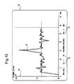
- step S5 When presenting a magnified display using such data, as shown in Fig. 12, in step S5, upper and lower limit data are entered using the keyboard 9. The limit data control how much of the machining voltage axis and the machining elapsed time axis will be displayed. The ranges are indicated in given areas 14 and 15 on the display screen 13 as shown in Fig. 13.
- step S6 the magnification factor of the machining voltage display is calculated using the upper and lower limit data for each axis entered in step S5, and fixed parameters relating to the size of the display region.
- step S7 the magnification factor of the display screen is changed using the value calculated in step S6.
- step S8 the machining voltage data points 12 stored in the memory 2 through machining voltage sampling processing are retrieved successively, beginning with the data collected at the start of machining.
- step S9 it is judged whether or not each machining voltage data point 12 thus retrieved falls between the upper and lower voltage and time limits entered in step S5. If the data falls within these limits, in step S10, it is graphically displayed within the machining voltage display area 16, and control proceeds to step S11. On the other hand, if the data falls outside the user-defined limits, control proceeds directly to step S11. In Step 11, it is judged whether or not all of the machining voltage data points 12 have been subjected to the processing of steps S8 through S11. If not, the next datum 12 is subjected to such processing. If so, processing comes to an end.
- step S1 it is judged whether machining is taking place or not. If no machining is taking place, the judgment of step S1 is simply repeated.
- step S12 current position data 17 sampled by the current position sampling unit 4 is extracted.
- step S13 the data extracted in step S12 is added to a group of current position data points (shown in Fig. 15) stored in the memory 2.
- step S14 the machining trace graphic display is presented using the current position data 17 so extracted. Then, control returns to step S1 to repeat the process.
- the group of current position data points are stored in the memory 2 through sampling processing, to be used in generating the display.
- step S15 input key information for designation of the range or frame 18 shown in Fig. 17 which defines the portion to be magnified is read.
- step S16 the coordinates of the range or frame thus designated are calculated on the basis of the keyed-in information.
- step S17 the magnification factor is calculated so as to enlarge the designated frame 18 to the size of the overall display area.
- step S18 the existing magnification factor is changed to the factor calculated in step S17.
- step S8 the current position data points 17 stored in the memory 2 through the sampling processing of Fig. 14 are retrieved successively starting from the machining start point.
- step S9 it is judged whether or not the coordinates of the position data point 17 currently being retrieved place it inside the frame obtained in step S16. If the point is inside the frame, in step S19, this current position data point 17 is graphically displayed on the trace display area 24, and control proceeds to step S11. On the other hand, if the point is not inside the frame, control proceeds directly to step S11.
- step S11 it is judged whether or not all the current position data points 17 have been subjected to the processing of steps S8 through S11. If not, the next current position data point 17 is subjected to this processing. The flowchart process is completed when all the data points have been processed.
- the machining trace 24 is initially presented on the display unit 13 as shown in Fig. 17.
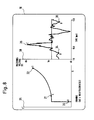
- the portion of the machining trace which is to be magnified for further display is designated. While there are several ways of accomplishing this designation, one manner which may be used is to designate points B, C and D (reference numerals 20-22) on the trace by the use of the cursor, to thereby allow automatic determination of the frame 18 defining the portion to be magnified. Following the determination of the frame, that portion of the machining trace inside the frame 18 is displayed on the graphic display area 25 in magnified form as shown in Fig. 18.
- the prior art adopts both machining trace graphic display processing and machining voltage display processing, but the two processes are completely independent of each other.
- machining speed display processing in the prior art is similar and is also completely independent of trace display processing.
- the machining voltage detecting unit 5 of Fig. 9 would be replaced with a machining speed detecting unit, and the machining voltage sampling unit 6 would be replaced with a machining speed sampling unit.
- the software would be essentially unchanged.
- the present invention has been devised to solve the foregoing defects. It is an object of the present invention to provide a system which is capable of displaying in simultaneous and correlative fashion representations of two or more parametric quantities whose values may change with a change in another quality, typically time. As an example, this object may be fulfilled by providing a system capable of commonly displaying graphic representations of two or more time-dependent parameters in such a way that the values of one parameter at a particular point or window of time can be easily correlated with the values of another parameter during the same time period.
- the numerical control device includes a display unit which presents a graphic display of machining voltage or machining speed versus elapsed machining time, as well as a display of the machining trace.
- a graphic display of machining voltage or machining speed versus elapsed machining time as well as a display of the machining trace.
- a magnified machined shape is displayed, and at the same time, a graphic display showing the variation of machining voltage or machining speed in relation to the elapsed machining time between the start and end positions of the magnified portion of the machined shape is displayed.
- Several other display options are also available, as described in the following detailed description.
- the display system of the present invention for example, upon the designation of a range on the machining trace graphic display, there is obtained the machining elapsed time at the start position and the end position of the designated portion of the machined shape, and the variation of the machining voltage or the machining speed within this interval is graphically displayed on the display unit.
- Fig. 1 elements which are analogous to those in Fig. 9 are similarly labeled.
- 26 is a timer unit for counting the elapsed machining time
- 27 is a sampling unit for sampling data from the timer unit 26, machining voltage measuring unit 5 and current position detecting unit 3 at a certain sampling interval, which may be on the order of 50 ms.
- Reference numeral 28 indicates a display correlating unit for causing the machining trace graphic display unit 7 and the machining voltage display unit 8 to operate in correlative relation, as discussed in detail below.
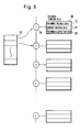
- Fig. 6 schematically represents the arrangement of the memory space in the storage of machining data. At each time interval of about 50 ms, readings of the machining position, the machining voltage (or speed, etc.) and the elapsed machining time are taken. These data are stored together as a block 30 in the memory.
- reference numeral 29 indicates the elapsed machining time data
- 12 is the machining voltage data
- 17 indicates the current position data, all of which are sampled, as noted, by the sampling unit 27.
- Reference numeral 31 represents a pointer for each machining condition data block 30, and 32 is an index which is used to store the pointers of blocks having machining condition data falling inside of the range or frame designated by the user on the machining trace graphic display or the machining voltage display, as described in more detail below.
- Fig. 8 shows one example of the display obtained according to the invention.
- 38 is a machining voltage display showing the variation of machining voltage in correlative relation to a part of the machining trace graphic display 25 presented in magnified form in accordance with the designated range or frame.
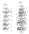
- step S1 it is judged whether machining is taking place or not. If no machining is taking place, step S1 is repeated. If machining is taking place, in step S20, the sampling unit 27 extracts the machining elapsed time data 29 from the timer unit 26, the current position data 17 from the current position detecting unit 3, and the current machining voltage data 12 from the machining voltage measuring unit 5. In step S21, a machining condition data block 30 as shown in Fig. 6 is formed and stored in the memory 2 using the data extracted in step S20. In step S14, the machining trace graphic display is presented using the current position data 17 extracted in step S20.
- step S4 the machining voltage display is presented using the machining voltage data 12 extracted in step S20. Then, control returns to step S1. As a result, machining condition data blocks 30 are formed and stored in the memory 2, and a substantially conventional display is generated on the display screen.
- step S15 information input from the keyboard is read, which is indicative of a range whose frame 18 defines the portion of the machining trace of interest.
- step S16 the coordinates of the range or frame designated by the input information are calculated.
- step S8 the machining condition data blocks 30 stored in the memory 2 through the machining condition sampling processing of Fig.
- step S9 it is judged whether or not the point expressed by the coordinates of the current position data 17 included in the machining condition data block 30 thus retrieved is inside the frame calculated in step S16. If the point is inside the frame, in step S22, the pointer 31 of the machining condition data block 30 is saved in the index 32. In step S23, overall maximum and minimum machining voltages are obtained (and updated), referring to the machining voltage data included in the "saved" machining condition data blocks. On the other hand, if the point is not inside the frame, control directly proceeds to step S11.
- step S11 it is judged whether or not all the machining condition data 30 blocks have been subjected to the processing of steps S8 through S11. If not, the next block 30 is subjected to this processing. On the other hand, if all the blocks have been processed, control proceeds to step S24.
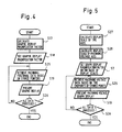
- step S24 on the basis of the index 32 obtained in steps S15 through S11, machining trace graphic display processing (as shown in Fig. 4) and machining voltage display processing (as shown in Fig. 5) are started, following which processing comes to an end.
- step S17 the factor of graphic display magnification is calculated on the basis of the coordinates of the frame obtained in step S16.
- the magnification factor of the display screen is set to correspond to the factor calculated in step S17.
- step S25 the machining condition data blocks 30 indicated by pointers stored in the index 32 obtained in step S22 are read.
- step S19 the machining trace display is presented on the basis of the current position data 17 included in the machining condition data blocks 30 thus read.
- step S26 it is judged whether or not all the pointers 31 stored in the index 32 (and the blocks 30 associated therewith) have been subjected to processing. If not, the next pointer 31 is read and the corresponding data block is subjected to the processing of steps S25 through S26.
- step S27 the scale for the time axis of the machining voltage display is obtained on the basis of the earliest and latest elapsed machining time data included in the machining condition data blocks whose pointers are stored in the index 32 obtained in step S22. This process does not require running through all the data again since the time data corresponding to the first and last entries in the index will yield this information. (As indicated previously, the data blocks are processed in time order, and thus the pointers appear in the index in chronological order of the elapsed time data).
- step S28 the scale for the machining voltage axis is obtained on the basis of the maximum and minimum machining voltages obtained in step S23.
- step S7 the magnification factor for the machining voltage data is set on the basis of the scale of the time axis as obtained in step S27 and the scale of the machining voltage axis as obtained in step S28.
- step S25 the voltage data of the machining condition data blocks 30 having elapsed time values between the earliest and latest times determined in step S27 are read. It should be noted that this reading step is not limited to the data blocks whose pointers appear in the index 32. Rather, the voltage data of all of the data blocks in the memory that fall within the elapsed time interval obtained in step S27 are read. A specific example of the importance of this distinction will be discussed later in connection with Fig. 5A.
- step S10 the machining voltage display is presented in its area of the display screen on the basis of the machining voltage data 12 and the elapsed machining time data 29 included in the machining condition data blocks as thus read.
- the machining trace display 24 and the machining voltage display 16 are presented on the display unit 13 shown in Fig. 7.
- the variation of the machining voltage corresponding to the machining trace thus displayed is displayed in the machining voltage display area 38.
- step S9 data blocks corresponding to machining taking place along segment 103 are not indexed. However, the voltage data of these blocks will be used in generating the voltage display shown in Fig. 5C. (The magnified machining trace appears on the left hand side of Fig. 5C).
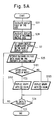
- Figure 5A is a flowchart of a procedure that can be used to highlight the voltage data which corresponds to machining outside of the designated range of the trace, i.e., such as along segment 103.
- This process is similar to that in Figure 5, except that after getting the voltage data of each block within the determined time range, it is checked in step S101 whether or not the block from which this particular voltage data came was previously indexed. If not, this means that the voltage datum in question comes from an out-of-range segment such as segment 103, and in step S102, this data is treated differently than the data which belongs to a previously indexed block, which is processed in step S103.
- the out-of-range voltage data may be displayed in a different color, or may be expressed as a dotted rather than solid line, or may be eliminated from the display altogether if desired. It is also an easy matter to delineate, such as by the display of suitable bars or markers, the beginning and end of the out-of-range voltage data, such as is seen in Fig. 5C.
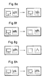
- FIG. 8a illustrates an arrangement wherein, starting from the base configuration shown in Fig. 7 (shown at left in each of Figs. 8a - 8k), a range on the machining trace is designated, following which that part of the voltage graph which corresponds to the designated range is processed for magnified display.
- Fig. 8b illustrates the arrangement wherein the designated machining trace and the corresponding portion of the voltage graph are both magnified for further display. This arrangement corresponds identically to that shown in Fig. 8 and need not be further discussed.
- Fig. 8c illustrates the alternative wherein, instead of designating a range of the machining trace, only a single point on the trace is selected.
- the upper illustration in Fig. 8c which proceeds from the base configuration of Fig. 7, after the point on the machining trace is designated, the corresponding point on the voltage graph is determined and suitably highlighted on the voltage graph, e.g., by indicating the point with a spot of a different color than the remaining display.
- the processing for this arrangement is essentially the trivial case of that discussed with respect to Fig. 8.
- designating a point on the machining trace it is not necessary to magnify either the machining trace or the voltage graph for further display.
- FIGS. 8c show alternatives wherein point designation is made not starting from the base arrangement of Fig. 7, but rather starting from the processed arrangements of Figs. 8a and 8b, respectively.
- Fig. 8d illustrates another modification wherein, upon designating a range on the machining trace, the corresponding portion of the voltage graph is highlighted, either by display in a differing color or other suitable means. No magnification of the voltage graph is necessary in this alternative.
- Fig. 8e shows a similar arrangement wherein only a point is designated on the machining trace. Here, the corresponding point on the voltage curve is indicated by a line perpendicular to the time axis of the graph.
- Fig. 8f is the first of several alternative display processing arrangements wherein the initial designation is made by selecting a range on the voltage vs. time curve rather than on the machining trace.
- the processing which is involved in this arrangement is entirely similar to that described in connection with Fig, 8 and therefore will not be separately illustrated.
- the selection and processing of the machining trace data to be subsequently displayed is carried out on the basis of the machining elapsed time data, so that the portion of the machining trace which corresponds to the time interval within the selected range of the voltage graph is made to appear in the machining trace portion of the display area, in magnified form.
- the arrangement shown in Fig. 8g is similar, except that here the designated range on the voltage graph is also magnified for subsequest display.
- Figs. 8h through 8j illustrate alternative display arrangements which are essentially similar to those in Figs. 8c, 8d and 8e, respectively.
- designation of a point on the voltage curve results in the highlighting of the corresponding point on the machining trace.
- This arrangement may have two other variations, not separately illustrated, similar to those shown in Fig. 8c.
- Fig.8i shows an alternative wherein the designation of a range on the voltage curve results in the highlighting of the corresponding portion of the machining trace.
- Fig. 8j illustrates a similar variant wherein designation of a particular point in time on the voltage graph via a line perpendicular to the time axis results in the highlighting of the corresponding point on the machining trace.
- Fig. 8h illustrate alternative display arrangements which are essentially similar to those in Figs. 8c, 8d and 8e, respectively.
- designation of a point on the voltage curve results in the highlighting of the corresponding point on the machining trace.
- Fig.8i shows an alternative
- 8k illustrates an alternative wherein, upon designating a range on the voltage curve, this portion of the curve is displayed in magnified form alongside either the original machining trace, with the corresponding portion highlighted, or a magnified enlargement of the corresponding section of the machining trace, as selected by the operator.
- magnification factor of the machining trace display or the voltage display are automatically calculated following the use of frame designation, the magnification factor may be entered in the form of a number, to the same effect.
- the machining speed or other parameters can be presented, by replacing the machining voltage with the machining speed or other parameter, in correlative relation and in normal and magnified modes as shown.
- a variation of machining voltage or machining speed is displayed in graphic form in relation to the elapsed machining time from the machining start position to the machining end position of the selected portion of the machining trace, or vice versa.
- the changing of the magnification factor is attained by designating the range or frame on the machining trace graphic display area or the voltage graph, or by entering the factor of display magnification in the form of a number.
- the invention has been described in the context of a numerically controlled machine tool such as an EDM machining apparatus, the invention has applicability to the field of display processing in general, and may find utility in any field wherein it is desired to simultaneously or sequentially display two or more parameters which are related through a common quality such as time.
- the invention is thus of particular usefulness in connection with monitoring or testing instrumentation capable of making multiple parametric measurements over the same or overlapping spans of time. For this reason, it is considered that the scope of the invention shall be measured solely by the claims which follow.
Landscapes
- Engineering & Computer Science (AREA)
- Automation & Control Theory (AREA)
- General Physics & Mathematics (AREA)
- Physics & Mathematics (AREA)
- Theoretical Computer Science (AREA)
- Chemical & Material Sciences (AREA)
- Chemical Kinetics & Catalysis (AREA)
- Electrochemistry (AREA)
- Mechanical Engineering (AREA)
- Manufacturing & Machinery (AREA)
- Human Computer Interaction (AREA)
- Electrical Discharge Machining, Electrochemical Machining, And Combined Machining (AREA)
- Numerical Control (AREA)
Applications Claiming Priority (2)
| Application Number | Priority Date | Filing Date | Title |
|---|---|---|---|
| JP32151/90 | 1990-02-13 | ||
| JP2032151A JPH03264215A (ja) | 1990-02-13 | 1990-02-13 | 放電加工機用数値制御装置 |
Publications (2)
| Publication Number | Publication Date |
|---|---|
| EP0442059A2 true EP0442059A2 (de) | 1991-08-21 |
| EP0442059A3 EP0442059A3 (en) | 1992-04-15 |
Family
ID=12350914
Family Applications (1)
| Application Number | Title | Priority Date | Filing Date |
|---|---|---|---|
| EP19900122847 Withdrawn EP0442059A3 (en) | 1990-02-13 | 1990-11-29 | Display processing apparatus |
Country Status (4)
| Country | Link |
|---|---|
| US (1) | US5144212A (de) |
| EP (1) | EP0442059A3 (de) |
| JP (1) | JPH03264215A (de) |
| KR (2) | KR930011851B1 (de) |
Cited By (4)
| Publication number | Priority date | Publication date | Assignee | Title |
|---|---|---|---|---|
| EP0663257A3 (de) * | 1994-01-13 | 1995-12-27 | Fanuc Ltd | Überwachungsvorrichtung für Funkenerosionsmaschine. |
| EP0649698A4 (de) * | 1993-05-10 | 1996-08-07 | Fanuc Ltd | Vorrichtung zum elektroerosiven bearbeiten. |
| EP0870265A4 (de) * | 1995-06-02 | 1998-10-14 | ||
| DE102011108896B4 (de) | 2010-08-06 | 2022-11-03 | Fanuc Corporation | System zum Erfassen von Bearbeitungsinformationen in einer Bearbeitungsvorrichtung, die an einer Bearbeitungsposition Energie oder Material zuführt |
Families Citing this family (17)
| Publication number | Priority date | Publication date | Assignee | Title |
|---|---|---|---|---|
| JPH068054A (ja) * | 1992-06-25 | 1994-01-18 | Fanuc Ltd | ワイヤカット放電加工機の放電加工モニタ方法 |
| JP3014562B2 (ja) * | 1993-05-07 | 2000-02-28 | ファナック株式会社 | 放電加工装置及び放電加工装置の加工条件設定方法 |
| WO1999058281A1 (en) * | 1998-05-13 | 1999-11-18 | Mitsubishi Denki Kabushiki Kaisha | Numeric control apparatus for wire electric spark machine |
| KR100541116B1 (ko) * | 1998-12-31 | 2006-03-23 | 두산인프라코어 주식회사 | 와이어 방전 가공기에 있어서의 가공방법 |
| JP3670633B2 (ja) * | 2002-08-21 | 2005-07-13 | ファナック株式会社 | ワイヤ放電加工機 |
| JP3981670B2 (ja) * | 2004-03-16 | 2007-09-26 | ファナック株式会社 | 加工形状描画装置 |
| JP2008009637A (ja) * | 2006-06-28 | 2008-01-17 | Okuma Corp | Ncプログラムの表示方法 |
| JP2008296314A (ja) * | 2007-05-30 | 2008-12-11 | Seibu Electric & Mach Co Ltd | ワイヤ放電加工装置の物理量変化状態表示システム |
| JP4648471B2 (ja) * | 2009-07-14 | 2011-03-09 | ファナック株式会社 | 工作機械の工具軌跡表示装置 |
| JP5428965B2 (ja) * | 2010-03-15 | 2014-02-26 | オムロン株式会社 | 表示装置、表示制御方法、プログラム、およびコンピュータ読み取り可能な記録媒体 |
| JP5088975B2 (ja) * | 2010-10-19 | 2012-12-05 | 株式会社ソディック | ワイヤ放電加工装置 |
| JP5073850B1 (ja) * | 2011-07-26 | 2012-11-14 | ファナック株式会社 | 音変換装置を備えた工作機械の数値制御装置 |
| JP5416238B2 (ja) * | 2012-02-27 | 2014-02-12 | ファナック株式会社 | データ管理機能を備えた波形表示装置 |
| JP2013196309A (ja) * | 2012-03-19 | 2013-09-30 | Fanuc Ltd | 加工状態情報表示装置 |
| CN105643030B (zh) * | 2016-03-01 | 2017-11-03 | 上海交通大学 | 一种用于多轴联动电火花加工的进给速度后处理器设计方法 |
| JP7088742B2 (ja) * | 2018-05-18 | 2022-06-21 | キヤノン電子株式会社 | 加工システム、加工機、加工機の制御方法及びプログラム |
| DE112022006366T5 (de) * | 2022-03-24 | 2024-11-14 | Fanuc Corporation | Anzeigevorrichtung und computerlesbares speichermedium |
Family Cites Families (5)
| Publication number | Priority date | Publication date | Assignee | Title |
|---|---|---|---|---|
| DE3029971A1 (de) * | 1979-08-09 | 1981-02-26 | Mitsubishi Electric Corp | Bearbeitungsvorrichtung zur bearbeitung eines werkstuecks durch elektrische entladung unter elektrischer stromzufuhr zum werkstueck und einer elektrode |
| JPS5971515A (ja) * | 1982-10-16 | 1984-04-23 | Fanuc Ltd | グラフィックディスプレイ装置 |
| US4574364A (en) * | 1982-11-23 | 1986-03-04 | Hitachi, Ltd. | Method and apparatus for controlling image display |
| US4855925A (en) * | 1987-04-14 | 1989-08-08 | Bhateja Chander P | Monitoring apparatus |
| JPS644828A (en) * | 1987-06-26 | 1989-01-10 | Sharp Kk | Image display control system |
-
1990
- 1990-02-13 JP JP2032151A patent/JPH03264215A/ja active Pending
- 1990-11-27 US US07/618,553 patent/US5144212A/en not_active Expired - Fee Related
- 1990-11-29 EP EP19900122847 patent/EP0442059A3/en not_active Withdrawn
-
1991
- 1991-02-04 KR KR1019910001843A patent/KR930011851B1/ko not_active Expired - Fee Related
-
1993
- 1993-10-29 KR KR1019930022676A patent/KR930011852B1/ko not_active Expired - Fee Related
Cited By (4)
| Publication number | Priority date | Publication date | Assignee | Title |
|---|---|---|---|---|
| EP0649698A4 (de) * | 1993-05-10 | 1996-08-07 | Fanuc Ltd | Vorrichtung zum elektroerosiven bearbeiten. |
| EP0663257A3 (de) * | 1994-01-13 | 1995-12-27 | Fanuc Ltd | Überwachungsvorrichtung für Funkenerosionsmaschine. |
| EP0870265A4 (de) * | 1995-06-02 | 1998-10-14 | ||
| DE102011108896B4 (de) | 2010-08-06 | 2022-11-03 | Fanuc Corporation | System zum Erfassen von Bearbeitungsinformationen in einer Bearbeitungsvorrichtung, die an einer Bearbeitungsposition Energie oder Material zuführt |
Also Published As
| Publication number | Publication date |
|---|---|
| EP0442059A3 (en) | 1992-04-15 |
| JPH03264215A (ja) | 1991-11-25 |
| US5144212A (en) | 1992-09-01 |
| KR930011852B1 (ko) | 1993-12-21 |
| KR910021282A (ko) | 1991-12-20 |
| KR930011851B1 (ko) | 1993-12-21 |
Similar Documents
| Publication | Publication Date | Title |
|---|---|---|
| US5144212A (en) | Display processing apparatus | |
| US10274932B2 (en) | Machining-information management device and tool-path generation device | |
| US7443396B2 (en) | Instrument having a virtual magnifying glass for displaying magnified portions of a signal waveform | |
| JP3472026B2 (ja) | ログ情報採取解析装置 | |
| US10152044B2 (en) | Control device for machine tool | |
| EP3437794A2 (de) | Vorrichtung und verfahren zur automatischen umwandlung von kompensationsparametern der thermischen verlagerung einer werkzeugmaschine | |
| KR860002004B1 (ko) | 수치제어가공 방식 | |
| JPS62277244A (ja) | 工作機械の適応制御装置 | |
| US6721621B1 (en) | Numerical controller for wire electrical discharge machine | |
| US6493602B1 (en) | Method of non-linear route display | |
| JP3822756B2 (ja) | データ処理装置 | |
| JP2000010622A (ja) | 履歴データ検索出力装置 | |
| US20210109130A1 (en) | Method and apparatus for controlling a measurement device | |
| JPS58119006A (ja) | 数値制御工作機械に於けるプログラム制御方法 | |
| JP2709092B2 (ja) | スペクトラム三次元表示方法 | |
| JP4458645B2 (ja) | 自動分析装置 | |
| JPS60118336A (ja) | 数値制御装置付パンチプレス機 | |
| JPH10104216A (ja) | クロマトデータ処理装置 | |
| JP3004494U (ja) | センサーコントローラ | |
| JPH06131025A (ja) | 数値制御装置における状態モニタの表示方法 | |
| JPH0962860A (ja) | 図形処理装置 | |
| JPH0773819B2 (ja) | Nc装置 | |
| JPS6142816B2 (de) | ||
| WO2017133022A1 (zh) | 一种数字示波器及其波形搜索方法和装置 | |
| JPH0682276A (ja) | 測定器のスケーリング方法 |
Legal Events
| Date | Code | Title | Description |
|---|---|---|---|
| PUAI | Public reference made under article 153(3) epc to a published international application that has entered the european phase |
Free format text: ORIGINAL CODE: 0009012 |
|
| 17P | Request for examination filed |
Effective date: 19901220 |
|
| AK | Designated contracting states |
Kind code of ref document: A2 Designated state(s): CH DE LI |
|
| PUAL | Search report despatched |
Free format text: ORIGINAL CODE: 0009013 |
|
| AK | Designated contracting states |
Kind code of ref document: A3 Designated state(s): CH DE LI |
|
| STAA | Information on the status of an ep patent application or granted ep patent |
Free format text: STATUS: THE APPLICATION HAS BEEN WITHDRAWN |
|
| 18W | Application withdrawn |
Withdrawal date: 19941024 |