EP0442119A2 - Method and apparatus for treating the dielectric used in electrical discharge machining - Google Patents
Method and apparatus for treating the dielectric used in electrical discharge machining Download PDFInfo
- Publication number
- EP0442119A2 EP0442119A2 EP90124981A EP90124981A EP0442119A2 EP 0442119 A2 EP0442119 A2 EP 0442119A2 EP 90124981 A EP90124981 A EP 90124981A EP 90124981 A EP90124981 A EP 90124981A EP 0442119 A2 EP0442119 A2 EP 0442119A2
- Authority
- EP
- European Patent Office
- Prior art keywords
- dielectric
- edming
- tank
- filter
- filtering
- Prior art date
- Legal status (The legal status is an assumption and is not a legal conclusion. Google has not performed a legal analysis and makes no representation as to the accuracy of the status listed.)
- Granted
Links
Images









Classifications
-
- B—PERFORMING OPERATIONS; TRANSPORTING
- B23—MACHINE TOOLS; METAL-WORKING NOT OTHERWISE PROVIDED FOR
- B23H—WORKING OF METAL BY THE ACTION OF A HIGH CONCENTRATION OF ELECTRIC CURRENT ON A WORKPIECE USING AN ELECTRODE WHICH TAKES THE PLACE OF A TOOL; SUCH WORKING COMBINED WITH OTHER FORMS OF WORKING OF METAL
- B23H1/00—Electrical discharge machining, i.e. removing metal with a series of rapidly recurring electrical discharges between an electrode and a workpiece in the presence of a fluid dielectric
- B23H1/10—Supply or regeneration of working media
Definitions
- the present invention relates to a method and an apparatus for treating the dielectric used in an electrical discharge machine tool (hereinafter referred to as an "EDM") wherein the dielectric is mixed with powder materials.
- EDM electrical discharge machine tool
- Japanese patent application No. 1990-15813 which is owned by the assignee of the present patent application, teaches that mixing the dielectric with certain kinds of materials in the form of powders of approximately 10 to 40 ⁇ m in particle diameter, to a mixing density of around 20 g/liter, improves the stability of discharge.
- the powder dielectric acts to upgrade mechanical characteristics, e.g., corrosion resistance and wear resistance, of the EDM electrode and the workpiece surface.
- EDMing allows the metal to be surface-treated.
- the powder materials used include semiconductor materials, e.g., silicon (Si), zinc oxide (ZnO), zinc dioxide (ZnO2), silicon dioxide (SiO2), tungsten carbide (WC) and zirconium boride (ZrB2), and fine ceramic materials, i.e., carbide and boride.
- semiconductor materials e.g., silicon (Si), zinc oxide (ZnO), zinc dioxide (ZnO2), silicon dioxide (SiO2), tungsten carbide (WC) and zirconium boride (ZrB2)
- fine ceramic materials i.e., carbide and boride.
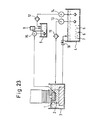
- FIG. 23 One dielectric treating apparatus for an EDM according to the background art is seen in Figure 23.
- An electrode 1 and a workpiece 2 are submerged in a dielectric within an EDMing tank 3.
- a dielectric tank 4 is connected to tank 3 and receives the dielectric drained from the bottom of tank 3 via valve 10.
- the drained dielectric may contain roughing chips 5 generated during roughing EDM operations, finishing chips 6 generated during finishing EDM operations and a powdered semiconductor material 7, such as silicon, as mentioned above.
- a tank 8 contains dielectric, supplied from tank 4 via pump 14 and filter 12, and receives raw powder from powder material supplier 9.
- a pump 13 operates to supply dielectric from dielectric tank 4 via filter 11 to the EDMing tank 3.
- the filters 11 and 12 are operative to remove chips from the dielectric pumped by pumps 13 and 14, respectively.
- the suspended powder is removed as well.
- a pump 15 supplies dielectric from the tank 8 to a discharge gap between the workpiece 2 and electrode 1 in tank 3.
- the workpiece 2 installed in the EDMing tank 3 is EDMed by electrical discharges in a discharge gap formed between the electrode 1 and the workpiece 2.
- chips 5 will be produced which will be suspended in the dielectric in the dielectric tank 4.
- the chips 5 so formed during the machining process will be carried to tank 4 via valve 10 when the dielectric is recirculated.
- the chip and dielectric suspension is then pumped by pump 13 to filter 11 wherein the chips and any powders are removed and the reclaimed dielectric is circulated back into the EDMing tank 3.
- dielectric mixed with the powder materials 7 from supplier 9 in tank 8 is pumped by the pump 15 from the tank 8 to the discharge gap formed by the electrode 1 and the workpiece 2.
- dielectric in tank 4 having a suspension of chips and powder materials 7 is pumped from the dielectric tank 4 into the tank 8 via filter 12, in order to remove any chips and powder.
- the powder materials 7 consumed by EDMing and filtering are replaced by powder from the powder material supplier 9, which is operated to automatically supply the powder materials 7 to the tank 8.
- the powder materials and the chips are treated together in the prior art EDM which does not consider the separation of the chips from the powder materials.
- finishing especially when accompanied by surface treatment, after a roughing step which produces numerous chips, finishing accuracy is greatly influenced by the numerous chips contained in the finishing dielectric. It is therefore necessary to continuously filter out the chips in the prior art.
- the powder materials are removed from the dielectric with the chips by the filtering process and then discarded, a large quantity of powder materials is consumed, which results in cost disadvantages.
- an object of the present invention to overcome the disadvantages in the prior art by providing a dielectric treatment apparatus for an EDM, which reduces the consumption of powder materials and allows the same powder materials to be reused over a long period of time.
- one or more dielectric tanks each having one or more compartments, are connected to an EDMing tank by pipes, defining input and output dielectric paths and having selectively placed therein pumps and control valves. Filters also may be added for removal of particles suspended in the dielectric.
- a roughing tank and a finishing tank are used for containing dielectric during respective roughing and finishing operations.
- the roughing tank may have plural compartments for storing dielectric from the EDMing tank.
- the waste particles in the dielectric may be filtered before being discharged into the roughing tank or may be directed to a first compartment in the roughing tank for storage prior to filtering and storage in a second compartment.
- a separate tank for storing dielectric used during finishing operations may be preferred in order to minimize chip contamination.
- the dielectric in the tank may be filtered to remove contaminants and deteriorated finishing powders.
- the roughing and finishing tanks may be combined into a single tank having plural compartments.
- a single tank, having a single compartment is used in a further embodiment.
- filtering of contaminants suspended in the discharge from the EDMing tank occurs prior to storage of the dielectric in the tank.
- a filter loop with input and output paths containing a bidirectional filter also can be used to filter powders that are in the stored dielectric.
- the EDMing tank is discharged directly into the single tank.
- the powder may be removed by the bidirectional filter and stored therein while the dielectric is reused for the roughing operation.
- the subsequent finishing operation is conducted by backwashing the filter with clean dielectric to wash the powder back into the dielectric.
- a filter may be selectively connected into the dielectric supply path between the dielectric tank and the EDMing tank and used to remove contaminants.
- valves and filters in the disclosed invention can occur automatically, in response to the output from various detectors, positioned to identify respective system parameters.
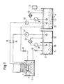
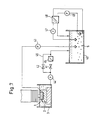
- Figure 1 illustrates a configuration of a dielectric treating apparatus for an EDM according to a first embodiment of the present invention.
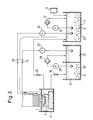
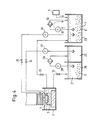
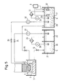
- Figures 2 to 4 illustrate a configuration of a dielectric treating apparatus shown in Figure 1.
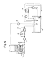
- Figure 5 illustrates a configuration of a dielectric treating apparatus according to a second embodiment of the present invention.
- Figure 6 illustrates a configuration of a dielectric treating apparatus according to a third embodiment of the present invention.
- Figure 7 illustrates a configuration of a dielectric treating apparatus according to a fourth embodiment of the present invention.
- Figures 8 to 10 illustrate operations of the dielectric treating apparatus according to a fifth embodiment of the present invention.
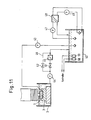
- Figure 11 illustrates a configuration of a dielectric treating apparatus according to the fifth embodiment of the present invention.
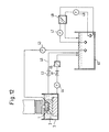
- Figure 12 illustrates a configuration of a dielectric treating apparatus according to a sixth embodiment of the present invention.
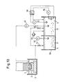
- Figure 13 illustrates a configuration of a dielectric treating apparatus according to a seventh embodiment of the present invention.
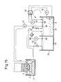
- FIGs 14 to 16 illustrate operations of the dielectric treating apparatus shown in Figure 13.
- Figure 17 illustrates a configuration of a dielectric treating apparatus according to an eighth embodiment of the present invention.
- Figure 18 illustrates a configuration of a dielectric treating apparatus according to a ninth embodiment of the present invention.
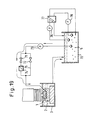
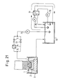
- FIGs 19 to 21 illustrate operations of the dielectric treating apparatus shown in Figure 18.
- Figure 22 illustrates a configuration of a dielectric treating apparatus according to a tenth embodiment of the present invention.
- Figure 23 illustrates a configuration of an EDM equipped with a conventional dielectric treating apparatus.
- Figure 1 illustrates the configuration of a dielectric treating apparatus for an EDM according to a first embodiment of the present invention.
- Figures 2 to 4 illustrate operations of the apparatus shown in Figure 1. Parts in these drawings identical to or corresponding to those of the conventional apparatus in Figure 23 are designated by identical reference characters and the explanation of their operation will not be repeated.
- a roughing dielectric tank 20 having a dirty dielectric compartment 21 for containing dirty dielectric recovered from the EDMing tank 3 and a clean dielectric compartment 22 for containing clean dielectric obtained by filtering the dirty dielectric in the dirty dielectric compartment 21, and a finishing dielectric tank 23.
- control valves 10 and 24-26 are used in the apparatus, control valves 10 and 26 being employed in drains used during roughing and finishing operations, respectively.
- the roughing and finishing drains from the EDMing tank 3 recover the dielectric and direct it into the tanks 20 and 23, respectively.
- a pump 27 is provided for the roughing dielectric tank 20 and connects the clean dielectric compartment 22 of tank 20 to the EDMing tank 3 via the control valve 24.
- a pump 28 is used to draw dielectric having a suspension of roughing chips from the dirty dielectric compartment 21 and provide the dielectric to the clean dielectric compartment 22 via a filter 29.
- a pump 30 is provided for the finishing dielectric tank 23 and connects the tank 23 to the EDMing tank 3 via the control valve 25.
- a pump 31 is employed for batch treatment of the dielectric in the finishing dielectric tank 23 so as to remove the powder materials and chips in the finishing dielectric tank 23 via the filter 12.
- Figure 2 illustrates a sequence of the dielectric flow during roughing.
- the dielectric in the clean dielectric compartment 22 of the roughing dielectric tank 20 is drawn by the pump 27 and introduced into the EDMing tank 3.
- the dielectric in the EDMing tank 3 becomes dirty due to chips formed during the roughing operations and is returned into the dirty dielectric compartment 21 of the roughing dielectric tank 20 by the control valve 10.
- the dielectric with roughing chips 5 is drawn by the pump 28 to the filter 29 and, as a result, clean dielectric is supplied for storage in the clean dielectric compartment 22.
- the roughing chips 5 are filtered during roughing continually or intermittently so that the clean dielectric free of the roughing chips 5 is always supplied to the EDMing tank 3 during a roughing operation.
- the finishing dielectric used as the dielectric in the finishing dielectric tank 23 is selected to have excellent finishing characteristics, particularly when mixed with the powder materials 7 by an operator or by the powder material supplier 9.
- This dielectric is drawn from tank 23 by the pump 30 and is supplied to the EDMing tank 3 and the discharge gap.
- the dielectric used for finishing is recovered from the EDMing tank 3 to the finishing dielectric tank 23 through the drain control valve 26.
- the powder materials 7 thus mixed in the dielectric are used repeatedly for EDMing.
- the chips 6 in the dielectric increase in number and the powder materials deteriorate, leading to degraded EDMing characteristics.
- the pump 31 is operated periodically during ordinary finishing as shown in Figure 4 to filter out the degraded powder materials 7 and the chips 6 for removal. This removal, however, need be carried out only every several hundred hours on a batch treatment basis because the powder materials 7 have a relatively long life and only a small amount of chips 6 are generated during finishing.
- the clean dielectric accumulated in the finishing dielectric tank 23 is supplied with new powder materials 7 by the operator or the powder material supplier 9 for use as new finishing dielectric.
- Figure 5 illustrates a configuration of a second embodiment of the present invention which is provided with a chip density sensor 32 in the finishing dielectric container, e.g., tank 23, so as to automatically remove the chips 6 and change the powder materials 7.
- the second embodiment allows the powder materials 7 to be batch-changed automatically in accordance with the EDMing amount.
- the finishing dielectric tank 23 may be provided with a powder particle diameter sensor, or a particle size distribution measuring device 33 for optically measuring the number of powder particles contained per unit volume, or the like, to automatically control filtering and/or addition of the powder materials 7.
- FIG. 6 illustrates a configuration of a third embodiment of the present invention, using a single tank but providing several compartments so that the roughing and finishing dielectrics are not mixed with each other.
- Figure 7 illustrates the configuration of a fourth embodiment of the present invention
- Figures 8 to 10 illustrate operation of the embodiment in Figure 7.
- the parts in these drawings identical or corresponding to those of the art in Figure 23 are specified by identical reference characters and an explanation thereof will not be repeated.
- a single dielectric container e.g., a tank, is connected to receive dielectric drained from EDMing tank 3.
- a pump 44 is employed for the drained dielectric and is connected in the drainage path from tank 3 to the dielectric tank 40 via the sludge filter 45 and the drained dielectric bypass 46.
- Control valves 41 and 42 are employed in the drainage path during roughing and finishing, respectively. The two valves are used to direct the dielectric drained from the EDMing tank 3 and recovered into the dielectric tank 40 to the EDMing tank 3.
- valve 42 is closed and valve 41 is open, thereby directing the dielectric to filter 45 where it is cleaned of debris and released to tank 40.
- a pump 43 is provided to direct dielectric in the dielectric tank 40 to the EDMing tank 3.
- pump 44 directs dielectric via open valve 42 into tank 40 from which it is pumped by pump 43 back into tank 3.
- Pump 47 may be used to draw dielectric from tank 40 to bidirectional filter 48. Filter 48 can remove powder materials when they are present in the finishing dielectric tank.
- a pump 49 is employed to draw dielectric from tank 40 and backwash the powder materials 7 collected in filter 48. This process will mix the powder materials 7 collected in the filter 48 into the dielectric in the dielectric tank 40 by flowing the dielectric in a direction opposite to that of the pump 47.
- FIG. 8 illustrates the sequence of the dielectric flow during roughing.
- the dielectric in the dielectric tank 40 is drawn by the pump 43 and directed into the EDMing tank 3.
- the dielectric in the EDMing tank 3 is discharged by the drain pump 44, delivered via the drain control valve 41 to the filter 45, where it is cleared of the roughing chips 5, and recovered into the dielectric tank 40.
- the roughing chips 5 are filtered off during roughing either at all times or intermittently so that the drained dielectric is always recovered into the dielectric tank 40 after it has been cleaned of the roughing chips 5. As a result, clean dielectric free of the roughing chips 5 is always supplied to the EDMing tank 3 and used for roughing.
- the pump 47 is operated as shown in Figure 10 to pass the dielectric having the powder materials 7 and the small quantity of chips 6 in the dielectric tank 40 through the filter 48, thereby cleaning the dielectric in the dielectric tank 40.
- the powder 7 is stored in the filter 48 until the next finishing operation.
- the powder materials 7 mixed in the dielectric as described above are used repeatedly for EDMing.
- the chips in the dielectric increase in number and the powder materials are deteriorated, resulting in degraded EDMing characteristics.
- the powder materials 7 must be changed periodically during ordinary finishing.
- the filter 48 since the powder materials 7 have a relatively long life and only a small amount of chips 6 are generated during finishing, the filter 48 only may be changed and a predetermined amount of new powder materials 7 supplied every several hundred hours.
- Figure 11 illustrates a configuration of a fifth embodiment of the present invention which is provided with a chip density sensor 50 in the dielectric container, e.g., tank 40, so as to identify when the chips 6 must be removed and the powder materials 7 changed.
- a chip density sensor 50 in the dielectric container, e.g., tank 40, so as to identify when the chips 6 must be removed and the powder materials 7 changed.
- a powder particle diameter sensor may be installed in the dielectric tank 40 to detect and identify when the powder materials have passed a threshold of deterioration, as determined by particle size.
- drained dielectric bypass 46 is installed in series with the pump 44 in the fifth embodiment, it may be installed in parallel with the drained dielectric line without connecting the drained dielectric pump 44, as shown in Figure 12, which illustrates a configuration of a sixth embodiment of the present invention.
- Figure 13 illustrates the configuration of a seventh the embodiment of the present invention
- Figures 14 to 16 illustrate the operation of the seventh embodiment in Figure 13.
- the parts in these drawings identical or corresponding to those of the art in Figure 23 are specified by the identical reference characters and will not be re-explained.
- a dielectric container 50 e.g., a tank, has a dirty dielectric compartment 51 for containing dirty dielectric recovered from the EDMing tank 3, and a clean dielectric compartment 52 for containing clean dielectric obtained by filtering the dirty dielectric in the dirty dielectric compartment 51.
- Control valves 53 and 54 are employed to establish drain paths from tank 3 during roughing and finishing operations, respectively. The drain from the EDMing tank 3 is directed into the compartments 51 and 52, respectively.
- a pump 43 is connected between the dielectric tank 52 and the EDMing tank 3.
- a pump 55 is connected between compartments 51 and 52 and directs dielectric through filter 56 to filter out the roughing chips in the dirty dielectric.
- a pump 57 is employed to draw dielectric from compartment 52 through filter 58 in order to filter the powder materials 7 and provide clean dielectric to compartment 52 via a filter 58.
- a pump 59 is employed to backwash the powder materials 7 in filter 58 and provide clean dielectric from tank 52 so as to mix the powder materials 7 in the filter 58 into the clean dielectric tank 52 by flowing the dielectric in the opposite direction.
- Figure 14 illustrates the sequence of the dielectric flow during roughing.
- the dielectric in the clean dielectric compartment 52 of the roughing dielectric tank 50 is drawn by the pump 43 and introduced into the EDMing tank 3.
- the dielectric in the EDMing tank 3 is returned to the dirty dielectric compartment 51 by the control valve 53, then pump 55 directs the dirty dielectric with roughing chips 5 through the filter 56, and the clean dielectric is accumulated in the clean dielectric compartment 52.
- the roughing chips 5 are filtered off during roughing at all times or intermittently so that the clean dielectric, free of roughing chips 5, is supplied to the EDMing tank 3 during roughing.
- the pump 59 Prior to the finishing operation, the pump 59 is operated to backwash the filter 58 and mix the powder materials 7 accumulated in the filter 58 into the clean dielectric compartment 52.
- the dielectric fully mixed with the powder materials 7 is drawn by the pump 43 and supplied to the EDMing tank 3 and the discharge gap.
- the dielectric used for finishing is recovered from the EDMing tank 3 to the clean dielectric compartment 52 via the drain control valve 54.
- the pump 57 is operated as shown in Figure 16 to have the powder materials 7 and the chips 6 in the clean dielectric compartment 52 removed by the filter 58, thereby cleaning the dielectric in the clean dielectric compartment 52.
- the filter 58 may be changed and a predetermined amount of new powder materials 7 supplied every several hundred hours.
- Figure 17 illustrates the configuration of an eighth embodiment of the present invention which is provided with a chip density sensor 50 in the clean dielectric compartment 52 so as to identify when the chips 6 should be removed and the powder materials 7 changed. Further, since the deterioration degree of the powder materials 7 is indicated as a change in particle diameter of the powders, a powder particle diameter sensor, a particle size distribution measuring device 61 for optically measuring the powder contained per unit volume, or the like may be installed in the clean dielectric compartment 52 to identify when the powder materials should be changed.
- Figure 18 illustrates the configuration of a ninth embodiment of the present invention
- Figures 19 to 21 illustrate the operation of this embodiment.
- Parts in these drawings identical or corresponding to those of the art in Figure 23 are designated by the identical reference characters and will not be re-explained.
- a dielectric container 70 e.g., a tank, and control valves 71 and 72 are employed to supply the dielectric during roughing and finishing operations, respectively.
- the dielectric from the dielectric tank 70 is delivered into the EDMing tank 3 directly.
- a pump 73 is employed to supply the dielectric and is connected between the dielectric tank 70 and the EDMing tank 3 via a filter 74 and a dielectric supply bypass 75.
- the control valves 71 and 72 function to switch between the filter 74 and the dielectric supply bypass 75.
- pump 76 is used to direct the dielectric with the powder materials 7 to a filter 77, where the powder is stored, and return clean dielectric to the dielectric tank 70 for use during a subsequent roughing operation, as described above.
- a pump 78 is employed to backwash the powder materials 7 with clean dielectric and provide finishing dielectric to tank 70.
- the powder materials 7 stored in the filter 77 are placed into the dielectric and stored in the dielectric tank 70 by flowing the dielectric in the opposite direction.
- Figure 19 illustrates with sequence of dielectric flow during roughing.
- the dielectric in the dielectric tank 70 is delivered by the dielectric supplying pump 73 to the filter 74, then cleaned of roughing chips 5, and sent to the EDMing tank 3.
- the roughing chips 5 are filtered off at all times during roughing so that clean dielectric without roughing chips 5 is always supplied to the EDMing tank 3 and used for roughing.
- the pump 78 is operated to backwash the filter 77 and mix the powder materials 7 accumulated in the filter 77 into the dielectric tank 70.
- the dielectric fully mixed with the powder materials 7 is drawn by the pump 73 and supplied to the EDMing tank 3 through the dielectric supply bypass 75 via the dielectric supplying control valve 72.
- the pump 76 is operated as shown in Figure 21 to have the powder materials 7 and the chips 6 in the dielectric tank 70 removed by the filter 77, whereby the dielectric in the dielectric tank 70 is cleaned.
- the filter 77 need only be changed, and the predetermined amount of new powder materials 7 supplied, every several hundred hours.
- Figure 22 illustrates the configuration of a tenth embodiment of the present invention which is provided with a chip density sensor 79 in the dielectric container, e.g., tank 70, so as to identify when the chips 6 should be removed and the powder materials 7 changed.
- a chip density sensor 79 in the dielectric container, e.g., tank 70, so as to identify when the chips 6 should be removed and the powder materials 7 changed.
- a particle size distribution measuring device 80 for optically measuring the powders contained per unit volume, or the like, may be installed in the dielectric tank 70 to identify when the powder materials 7 should be changed.
- the invention achieves a dielectric treating apparatus which allows dielectric including powder materials to be used repeatedly for a long period of time, whereby high-priced powder materials can be employed efficiently and machining or surface treatment utilizing EDMing may be conducted economically.
- the present invention can present an economical EDM which is excellent in machining accuracy and characteristics and low in operating costs.
Landscapes
- Engineering & Computer Science (AREA)
- Mechanical Engineering (AREA)
- Electrical Discharge Machining, Electrochemical Machining, And Combined Machining (AREA)
Abstract
Description
- The present invention relates to a method and an apparatus for treating the dielectric used in an electrical discharge machine tool (hereinafter referred to as an "EDM") wherein the dielectric is mixed with powder materials.
- In the EDMing arts, it is well known to perform melt processing or heat treatment on a workpiece made of an electrically conductive material, e.g., metal, by utilizing the high-temperature energy generated in an electrical discharge path. The discharge gap is filled with dielectric having electrical insulation characteristics to obtain the electrical insulation required for discharge. Usually an oil or oil/water mixture is used as the dielectric. Besides obtaining electrical insulation, the dielectric functions to remove chips produced during the machining process and to remove the resultant heat from the machining site, thereby acting as an important factor in maintaining stable EDMing.
- Japanese patent application No. 1990-15813, which is owned by the assignee of the present patent application, teaches that mixing the dielectric with certain kinds of materials in the form of powders of approximately 10 to 40 µm in particle diameter, to a mixing density of around 20 g/liter, improves the stability of discharge. Depending on the material, the powder dielectric acts to upgrade mechanical characteristics, e.g., corrosion resistance and wear resistance, of the EDM electrode and the workpiece surface. In addition to the removal of material (e.g., metal) from the workpiece, EDMing allows the metal to be surface-treated. The powder materials used include semiconductor materials, e.g., silicon (Si), zinc oxide (ZnO), zinc dioxide (ZnO₂), silicon dioxide (SiO₂), tungsten carbide (WC) and zirconium boride (ZrB₂), and fine ceramic materials, i.e., carbide and boride.
- It has been proposed to machine a workpiece or form a surface layer thereon by mixing such materials in powder form into the dielectric. This proposal would vastly expand the application range of EDM. The problem is to provide for practical implementation of the proposal. Specifically, one goal is to design an apparatus for efficiently treating the dielectric used in EDMing.
- One dielectric treating apparatus for an EDM according to the background art is seen in Figure 23. There an electrode 1 and a
workpiece 2 are submerged in a dielectric within anEDMing tank 3. A dielectric tank 4 is connected totank 3 and receives the dielectric drained from the bottom oftank 3 viavalve 10. The drained dielectric may contain roughingchips 5 generated during roughing EDM operations, finishingchips 6 generated during finishing EDM operations and a powderedsemiconductor material 7, such as silicon, as mentioned above. Atank 8 contains dielectric, supplied from tank 4 viapump 14 andfilter 12, and receives raw powder frompowder material supplier 9. Apump 13 operates to supply dielectric from dielectric tank 4 viafilter 11 to theEDMing tank 3. Thefilters pumps pump 15 supplies dielectric from thetank 8 to a discharge gap between theworkpiece 2 and electrode 1 intank 3. - Operation of the EDM as above constructed can be understood with reference to Figure 23. In an ordinary roughing process, the
workpiece 2 installed in theEDMing tank 3 is EDMed by electrical discharges in a discharge gap formed between the electrode 1 and theworkpiece 2. In this process,chips 5 will be produced which will be suspended in the dielectric in the dielectric tank 4. Thechips 5 so formed during the machining process will be carried to tank 4 viavalve 10 when the dielectric is recirculated. The chip and dielectric suspension is then pumped bypump 13 to filter 11 wherein the chips and any powders are removed and the reclaimed dielectric is circulated back into theEDMing tank 3. When surface treatment, and the like, is to be carried out by finishing machining after roughing, clean dielectric mixed with thepowder materials 7 fromsupplier 9 intank 8 is pumped by thepump 15 from thetank 8 to the discharge gap formed by the electrode 1 and theworkpiece 2. At the same time, dielectric in tank 4, having a suspension of chips andpowder materials 7, is pumped from the dielectric tank 4 into thetank 8 viafilter 12, in order to remove any chips and powder. Thepowder materials 7 consumed by EDMing and filtering are replaced by powder from thepowder material supplier 9, which is operated to automatically supply thepowder materials 7 to thetank 8. - As mentioned above, the powder materials and the chips are treated together in the prior art EDM which does not consider the separation of the chips from the powder materials. In addition, when finishing is performed, especially when accompanied by surface treatment, after a roughing step which produces numerous chips, finishing accuracy is greatly influenced by the numerous chips contained in the finishing dielectric. It is therefore necessary to continuously filter out the chips in the prior art. Finally, since the powder materials are removed from the dielectric with the chips by the filtering process and then discarded, a large quantity of powder materials is consumed, which results in cost disadvantages.
- It is, accordingly, an object of the present invention to overcome the disadvantages in the prior art by providing a dielectric treatment apparatus for an EDM, which reduces the consumption of powder materials and allows the same powder materials to be reused over a long period of time.
- It is another object of the present invention to filter and store powder materials for reuse with a simple apparatus.
- It is a further object of the present invention to automatically detect the deterioration of the powder materials and replace such materials in response to such detection.
- These and other objects of the present invention are accomplished in several embodiments in which one or more dielectric tanks, each having one or more compartments, are connected to an EDMing tank by pipes, defining input and output dielectric paths and having selectively placed therein pumps and control valves. Filters also may be added for removal of particles suspended in the dielectric.
- In one embodiment, a roughing tank and a finishing tank are used for containing dielectric during respective roughing and finishing operations. The roughing tank may have plural compartments for storing dielectric from the EDMing tank. The waste particles in the dielectric may be filtered before being discharged into the roughing tank or may be directed to a first compartment in the roughing tank for storage prior to filtering and storage in a second compartment. A separate tank for storing dielectric used during finishing operations may be preferred in order to minimize chip contamination. The dielectric in the tank may be filtered to remove contaminants and deteriorated finishing powders. The roughing and finishing tanks may be combined into a single tank having plural compartments.
- A single tank, having a single compartment is used in a further embodiment. During a roughing operation, filtering of contaminants suspended in the discharge from the EDMing tank occurs prior to storage of the dielectric in the tank. A filter loop with input and output paths containing a bidirectional filter also can be used to filter powders that are in the stored dielectric. During a finishing operation, the EDMing tank is discharged directly into the single tank. At the end of the finishing operation, the powder may be removed by the bidirectional filter and stored therein while the dielectric is reused for the roughing operation. The subsequent finishing operation is conducted by backwashing the filter with clean dielectric to wash the powder back into the dielectric.
- A filter may be selectively connected into the dielectric supply path between the dielectric tank and the EDMing tank and used to remove contaminants.
- Various combinations of inputs, discharge and filter paths may be used with various designs of dielectric tanks, having one or more compartments, in order to meet particular operational requirements.
- The operation of valves and filters in the disclosed invention can occur automatically, in response to the output from various detectors, positioned to identify respective system parameters.
- Figure 1 illustrates a configuration of a dielectric treating apparatus for an EDM according to a first embodiment of the present invention.
- Figures 2 to 4 illustrate a configuration of a dielectric treating apparatus shown in Figure 1.
- Figure 5 illustrates a configuration of a dielectric treating apparatus according to a second embodiment of the present invention.
- Figure 6 illustrates a configuration of a dielectric treating apparatus according to a third embodiment of the present invention.
- Figure 7 illustrates a configuration of a dielectric treating apparatus according to a fourth embodiment of the present invention.
- Figures 8 to 10 illustrate operations of the dielectric treating apparatus according to a fifth embodiment of the present invention.
- Figure 11 illustrates a configuration of a dielectric treating apparatus according to the fifth embodiment of the present invention.
- Figure 12 illustrates a configuration of a dielectric treating apparatus according to a sixth embodiment of the present invention.
- Figure 13 illustrates a configuration of a dielectric treating apparatus according to a seventh embodiment of the present invention.
- Figures 14 to 16 illustrate operations of the dielectric treating apparatus shown in Figure 13.
- Figure 17 illustrates a configuration of a dielectric treating apparatus according to an eighth embodiment of the present invention.
- Figure 18 illustrates a configuration of a dielectric treating apparatus according to a ninth embodiment of the present invention.
- Figures 19 to 21 illustrate operations of the dielectric treating apparatus shown in Figure 18.
- Figure 22 illustrates a configuration of a dielectric treating apparatus according to a tenth embodiment of the present invention.
- Figure 23 illustrates a configuration of an EDM equipped with a conventional dielectric treating apparatus.
- Figure 1 illustrates the configuration of a dielectric treating apparatus for an EDM according to a first embodiment of the present invention. Figures 2 to 4 illustrate operations of the apparatus shown in Figure 1. Parts in these drawings identical to or corresponding to those of the conventional apparatus in Figure 23 are designated by identical reference characters and the explanation of their operation will not be repeated.
- In Figure 1, several dielectric containers are used, including a
roughing dielectric tank 20 having adirty dielectric compartment 21 for containing dirty dielectric recovered from theEDMing tank 3 and aclean dielectric compartment 22 for containing clean dielectric obtained by filtering the dirty dielectric in thedirty dielectric compartment 21, and a finishingdielectric tank 23.Several control valves 10 and 24-26 are used in the apparatus,control valves EDMing tank 3 recover the dielectric and direct it into thetanks pump 27 is provided for theroughing dielectric tank 20 and connects theclean dielectric compartment 22 oftank 20 to theEDMing tank 3 via thecontrol valve 24. Apump 28 is used to draw dielectric having a suspension of roughing chips from thedirty dielectric compartment 21 and provide the dielectric to theclean dielectric compartment 22 via afilter 29. - A
pump 30 is provided for the finishingdielectric tank 23 and connects thetank 23 to theEDMing tank 3 via thecontrol valve 25. Apump 31 is employed for batch treatment of the dielectric in the finishingdielectric tank 23 so as to remove the powder materials and chips in the finishingdielectric tank 23 via thefilter 12. - Operation of the first embodiment of the present invention will now be described with reference to the drawings. Figure 2 illustrates a sequence of the dielectric flow during roughing. The dielectric in the
clean dielectric compartment 22 of theroughing dielectric tank 20 is drawn by thepump 27 and introduced into theEDMing tank 3. The dielectric in theEDMing tank 3 becomes dirty due to chips formed during the roughing operations and is returned into thedirty dielectric compartment 21 of theroughing dielectric tank 20 by thecontrol valve 10. The dielectric withroughing chips 5 is drawn by thepump 28 to thefilter 29 and, as a result, clean dielectric is supplied for storage in theclean dielectric compartment 22. The roughing chips 5 are filtered during roughing continually or intermittently so that the clean dielectric free of theroughing chips 5 is always supplied to theEDMing tank 3 during a roughing operation. - The sequence of the dielectric flow during finishing will now be described according to Figure 3. The finishing dielectric used as the dielectric in the finishing
dielectric tank 23 is selected to have excellent finishing characteristics, particularly when mixed with thepowder materials 7 by an operator or by thepowder material supplier 9. This dielectric is drawn fromtank 23 by thepump 30 and is supplied to theEDMing tank 3 and the discharge gap. The dielectric used for finishing is recovered from theEDMing tank 3 to the finishingdielectric tank 23 through thedrain control valve 26. - Generally, the
powder materials 7 thus mixed in the dielectric are used repeatedly for EDMing. However, if EDMing is repeated for a long period of time, thechips 6 in the dielectric increase in number and the powder materials deteriorate, leading to degraded EDMing characteristics. To prevent this, thepump 31 is operated periodically during ordinary finishing as shown in Figure 4 to filter out thedegraded powder materials 7 and thechips 6 for removal. This removal, however, need be carried out only every several hundred hours on a batch treatment basis because thepowder materials 7 have a relatively long life and only a small amount ofchips 6 are generated during finishing. After being cleared of thepowder materials 7, the clean dielectric accumulated in the finishingdielectric tank 23 is supplied withnew powder materials 7 by the operator or thepowder material supplier 9 for use as new finishing dielectric. - Figure 5 illustrates a configuration of a second embodiment of the present invention which is provided with a
chip density sensor 32 in the finishing dielectric container, e.g.,tank 23, so as to automatically remove thechips 6 and change thepowder materials 7. The second embodiment allows thepowder materials 7 to be batch-changed automatically in accordance with the EDMing amount. In addition, since the degree of deterioration of thepowder materials 7 is inversely related to particle diameter of the powders (the particle size decreases with use), the finishingdielectric tank 23 may be provided with a powder particle diameter sensor, or a particle sizedistribution measuring device 33 for optically measuring the number of powder particles contained per unit volume, or the like, to automatically control filtering and/or addition of thepowder materials 7. - While the
roughing dielectric tank 20 and the finishingdielectric tank 23 are provided separately in each of the first and the second embodiments, the same effect may be produced by providing one dielectric container having a plurality of compartments, instead of two dielectric containers. Figure 6 illustrates a configuration of a third embodiment of the present invention, using a single tank but providing several compartments so that the roughing and finishing dielectrics are not mixed with each other. - Figure 7 illustrates the configuration of a fourth embodiment of the present invention, and Figures 8 to 10 illustrate operation of the embodiment in Figure 7. The parts in these drawings identical or corresponding to those of the art in Figure 23 are specified by identical reference characters and an explanation thereof will not be repeated.
- In Figures 7-10, a single dielectric container, e.g., a tank, is connected to receive dielectric drained from
EDMing tank 3. Apump 44 is employed for the drained dielectric and is connected in the drainage path fromtank 3 to thedielectric tank 40 via thesludge filter 45 and the draineddielectric bypass 46.Control valves EDMing tank 3 and recovered into thedielectric tank 40 to theEDMing tank 3. During a roughing operation,valve 42 is closed andvalve 41 is open, thereby directing the dielectric to filter 45 where it is cleaned of debris and released totank 40. Apump 43 is provided to direct dielectric in thedielectric tank 40 to theEDMing tank 3. - During a finishing operation, pump 44 directs dielectric via
open valve 42 intotank 40 from which it is pumped bypump 43 back intotank 3.Pump 47 may be used to draw dielectric fromtank 40 tobidirectional filter 48.Filter 48 can remove powder materials when they are present in the finishing dielectric tank. - Further, a
pump 49 is employed to draw dielectric fromtank 40 and backwash thepowder materials 7 collected infilter 48. This process will mix thepowder materials 7 collected in thefilter 48 into the dielectric in thedielectric tank 40 by flowing the dielectric in a direction opposite to that of thepump 47. - Operation of the fourth embodiment will now be described in reference to the drawings. Figure 8 illustrates the sequence of the dielectric flow during roughing. The dielectric in the
dielectric tank 40 is drawn by thepump 43 and directed into theEDMing tank 3. The dielectric in theEDMing tank 3 is discharged by thedrain pump 44, delivered via thedrain control valve 41 to thefilter 45, where it is cleared of theroughing chips 5, and recovered into thedielectric tank 40. The roughing chips 5 are filtered off during roughing either at all times or intermittently so that the drained dielectric is always recovered into thedielectric tank 40 after it has been cleaned of theroughing chips 5. As a result, clean dielectric free of theroughing chips 5 is always supplied to theEDMing tank 3 and used for roughing. - A sequence of the dielectric flow during finishing will now be described according to Figure 9. Prior to the finishing operation, the
pump 49 is operated to backwash thefilter 48 and mix thepowder materials 7 accumulated in thefilter 48 into thedielectric tank 40. Once the dielectric is fully mixed with thepowder materials 7 it is drawn by thepump 43 and supplied to theEDMing tank 3 and the discharge gap. The dielectric used for finishing is recovered from theEDMing tank 3 to thedielectric tank 40 via thedrain control valve 42 through the draineddielectric bypass 46.Valve 41 is closed at this time. Accordingly, the drained dielectric during finishing is recovered into thedielectric tank 40 without being filtered, but this poses no practical problem because the amount of chips generated during finishing is extremely small. - After finishing, the
pump 47 is operated as shown in Figure 10 to pass the dielectric having thepowder materials 7 and the small quantity ofchips 6 in thedielectric tank 40 through thefilter 48, thereby cleaning the dielectric in thedielectric tank 40. Particularly, thepowder 7 is stored in thefilter 48 until the next finishing operation. - Generally, the
powder materials 7 mixed in the dielectric as described above are used repeatedly for EDMing. However, if EDMing is repeated for a long period of time, the chips in the dielectric increase in number and the powder materials are deteriorated, resulting in degraded EDMing characteristics. To prevent this, thepowder materials 7 must be changed periodically during ordinary finishing. However, since thepowder materials 7 have a relatively long life and only a small amount ofchips 6 are generated during finishing, thefilter 48 only may be changed and a predetermined amount ofnew powder materials 7 supplied every several hundred hours. - Figure 11 illustrates a configuration of a fifth embodiment of the present invention which is provided with a
chip density sensor 50 in the dielectric container, e.g.,tank 40, so as to identify when thechips 6 must be removed and thepowder materials 7 changed. - Since the degree with which the
powder materials 7 have deteriorated is indicated by the particle diameter of the powders, a powder particle diameter sensor, a particle sizedistribution measuring device 51 for optically measuring the number of particles contained per unit volume, or the like, may be installed in thedielectric tank 40 to detect and identify when the powder materials have passed a threshold of deterioration, as determined by particle size. - While the drained
dielectric bypass 46 is installed in series with thepump 44 in the fifth embodiment, it may be installed in parallel with the drained dielectric line without connecting the draineddielectric pump 44, as shown in Figure 12, which illustrates a configuration of a sixth embodiment of the present invention. - Figure 13 illustrates the configuration of a seventh the embodiment of the present invention, and Figures 14 to 16 illustrate the operation of the seventh embodiment in Figure 13. The parts in these drawings identical or corresponding to those of the art in Figure 23 are specified by the identical reference characters and will not be re-explained.
- In Figure 13 a
dielectric container 50, e.g., a tank, has adirty dielectric compartment 51 for containing dirty dielectric recovered from theEDMing tank 3, and aclean dielectric compartment 52 for containing clean dielectric obtained by filtering the dirty dielectric in thedirty dielectric compartment 51.Control valves tank 3 during roughing and finishing operations, respectively. The drain from theEDMing tank 3 is directed into thecompartments pump 43 is connected between thedielectric tank 52 and theEDMing tank 3. Apump 55 is connected betweencompartments filter 56 to filter out the roughing chips in the dirty dielectric. Apump 57 is employed to draw dielectric fromcompartment 52 throughfilter 58 in order to filter thepowder materials 7 and provide clean dielectric tocompartment 52 via afilter 58. Apump 59 is employed to backwash thepowder materials 7 infilter 58 and provide clean dielectric fromtank 52 so as to mix thepowder materials 7 in thefilter 58 into theclean dielectric tank 52 by flowing the dielectric in the opposite direction. - Operation of the seventh embodiment of the present invention will now be described with reference to the drawings. Figure 14 illustrates the sequence of the dielectric flow during roughing. The dielectric in the
clean dielectric compartment 52 of theroughing dielectric tank 50 is drawn by thepump 43 and introduced into theEDMing tank 3. The dielectric in theEDMing tank 3 is returned to thedirty dielectric compartment 51 by thecontrol valve 53, then pump 55 directs the dirty dielectric withroughing chips 5 through thefilter 56, and the clean dielectric is accumulated in theclean dielectric compartment 52. The roughing chips 5 are filtered off during roughing at all times or intermittently so that the clean dielectric, free ofroughing chips 5, is supplied to theEDMing tank 3 during roughing. - The sequence of dielectric flow during finishing will now be described according to Figure 15. Prior to the finishing operation, the
pump 59 is operated to backwash thefilter 58 and mix thepowder materials 7 accumulated in thefilter 58 into theclean dielectric compartment 52. The dielectric fully mixed with thepowder materials 7 is drawn by thepump 43 and supplied to theEDMing tank 3 and the discharge gap. The dielectric used for finishing is recovered from theEDMing tank 3 to theclean dielectric compartment 52 via thedrain control valve 54. After finishing, thepump 57 is operated as shown in Figure 16 to have thepowder materials 7 and thechips 6 in theclean dielectric compartment 52 removed by thefilter 58, thereby cleaning the dielectric in theclean dielectric compartment 52. As previously noted, since thepowder materials 7 have a relatively long life and a small amount ofchips 6 are generated during finishing, thefilter 58 may be changed and a predetermined amount ofnew powder materials 7 supplied every several hundred hours. - Figure 17 illustrates the configuration of an eighth embodiment of the present invention which is provided with a
chip density sensor 50 in theclean dielectric compartment 52 so as to identify when thechips 6 should be removed and thepowder materials 7 changed. Further, since the deterioration degree of thepowder materials 7 is indicated as a change in particle diameter of the powders, a powder particle diameter sensor, a particle size distribution measuring device 61 for optically measuring the powder contained per unit volume, or the like may be installed in theclean dielectric compartment 52 to identify when the powder materials should be changed. - Figure 18 illustrates the configuration of a ninth embodiment of the present invention, and Figures 19 to 21 illustrate the operation of this embodiment. Parts in these drawings identical or corresponding to those of the art in Figure 23 are designated by the identical reference characters and will not be re-explained.
- A
dielectric container 70, e.g., a tank, and controlvalves dielectric tank 70 is delivered into theEDMing tank 3 directly. Apump 73 is employed to supply the dielectric and is connected between thedielectric tank 70 and theEDMing tank 3 via afilter 74 and adielectric supply bypass 75. Thecontrol valves filter 74 and thedielectric supply bypass 75. After a finishing operation, pump 76 is used to direct the dielectric with thepowder materials 7 to afilter 77, where the powder is stored, and return clean dielectric to thedielectric tank 70 for use during a subsequent roughing operation, as described above. After a roughing operation, when another finishing operation is to be conducted, apump 78 is employed to backwash thepowder materials 7 with clean dielectric and provide finishing dielectric totank 70. Thepowder materials 7 stored in thefilter 77 are placed into the dielectric and stored in thedielectric tank 70 by flowing the dielectric in the opposite direction. - Operation of the ninth embodiment will now be described the reference to the drawings. Figure 19 illustrates with sequence of dielectric flow during roughing. The dielectric in the
dielectric tank 70 is delivered by the dielectric supplyingpump 73 to thefilter 74, then cleaned ofroughing chips 5, and sent to theEDMing tank 3. The roughing chips 5 are filtered off at all times during roughing so that clean dielectric without roughingchips 5 is always supplied to theEDMing tank 3 and used for roughing. - The sequence of dielectric flow during finishing will now be described according to Figure 20. Prior to finishing, the
pump 78 is operated to backwash thefilter 77 and mix thepowder materials 7 accumulated in thefilter 77 into thedielectric tank 70. The dielectric fully mixed with thepowder materials 7 is drawn by thepump 73 and supplied to theEDMing tank 3 through thedielectric supply bypass 75 via the dielectric supplyingcontrol valve 72. Although the dielectric supplied during finishing is supplied to theEDMing tank 3 without being filtered, this poses no practical problem because the amount of chips generated during finishing is extremely small. After finishing, thepump 76 is operated as shown in Figure 21 to have thepowder materials 7 and thechips 6 in thedielectric tank 70 removed by thefilter 77, whereby the dielectric in thedielectric tank 70 is cleaned. Thefilter 77 need only be changed, and the predetermined amount ofnew powder materials 7 supplied, every several hundred hours. - Figure 22 illustrates the configuration of a tenth embodiment of the present invention which is provided with a chip density sensor 79 in the dielectric container, e.g.,
tank 70, so as to identify when thechips 6 should be removed and thepowder materials 7 changed. - A particle size
distribution measuring device 80 for optically measuring the powders contained per unit volume, or the like, may be installed in thedielectric tank 70 to identify when thepowder materials 7 should be changed. - It will be apparent that the invention, as described above, achieves a dielectric treating apparatus which allows dielectric including powder materials to be used repeatedly for a long period of time, whereby high-priced powder materials can be employed efficiently and machining or surface treatment utilizing EDMing may be conducted economically.
- Therefore, the present invention can present an economical EDM which is excellent in machining accuracy and characteristics and low in operating costs.
- While the present invention has been described in connection with several preferred embodiments, it is not intended to be limited thereto and the full scope of the invention is to be defined by the appended claims.
Claims (20)
- An apparatus for treating dielectric for an EDM comprising:
dielectric containing means for containing EDMing dielectric;
first dielectric filtering means disposed in a liquid communication path connecting between said dielectric containing means and an EDMing tank for filtering a first EDMing dielectric; and
second dielectric filtering means for filtering a second EDMing dielectric after EDMing with said second dielectric. - An apparatus according to claim 1 wherein said dielectric containing means includes:
first dielectric containing means for containing a first EDMing dielectric, and
second dielectric containing means for containing a second EDMing dielectric;
said liquid communication path includes:
path means establishing liquid communication between said first dielectric containing means and said EDMing tank and between said second dielectric containing means and said EDMing tank;
control valve means, operative with said path means for controlling the flow of said dielectrics;
said first dielectric filtering means is disposed in at least one of said path means and;
said second dielectric filtering means is disposed in at least one of said path means. - An apparatus according to claim 1 or 2 wherein said path means includes:
first path means connecting between said first dielectric containing means and an EDMing tank;
said control valve means is disposed in said first path means; and
said second dielectric filtering means is in liquid communication with said second dielectric containing means and is operative to mix powder materials into said first EDMing dielectric to form said second EDMing dielectric at the start of EDMing with said second EDMing dielectric and to filter said second EDMing dielectric to form said first EDMing dielectric after EDMing with said second EDMing dielectric. - An apparatus according to any of claims 1 to 3 wherein said apparatus machines a workpiece positioned within said EDMing tank using an electrode, said electrode and said workpiece forming a discharge gap therebetween, said gap being supplied with said first EDMing dielectric or said second EDMing dielectric, having a higher resistance ratio than said first EDMing dielectric and made by mixing said first EDMing dielectric with powder materials, and said second dielectric filtering means is disposed in a second path means.
- An apparatus according to any of the claims 2 to 4, wherein said first dielectric containing means comprises a first compartment for receiving dielectric from said EDM tank and a second compartment, in fluid communication with said first compartment, for returning dielectric to said EDM tank.
- An apparatus according to claim 5, wherein said first and second compartments are in a single tank.
- An apparatus according to any of the claims 2 to 6, further comprising means for converting said first dielectric to said second dielectric by adding said powders to said first dielectric.
- An apparatus according to any of the claims 2 to 7, wherein said first and second dielectric containing means jointly comprise a single tank.
- An apparatus according to any one of claims 1 to 8, wherein said second dielectric filter means comprises bidirectional filter means operative in response to dielectric flow in a first direction to filter particulate material from said dielectric, and operative in response to dielectric flow in a second direction, opposite to said first direction, to return previously filtered particulate material to said dielectric.
- An apparatus according to any one of claims 1 to 9, further comprising means for detecting the deterioration of said powder material.
- An apparatus according to claim 10, wherein said means for detecting comprises means for measuring the size of particles in the dielectric.
- An apparatus according to claim 10 or 11, wherein said means for detecting comprises means for identifying the number of particles per unit volume of dielectric.
- An apparatus according to claim 11 or 12, further comprising means responsive to said detecting means for controlling at least one of the filtering of particles from said second dielectric and the generation of second dielectric with new powder material.
- A method of machining a workpiece using an electrical discharge machining apparatus (EDM), comprising the steps of:(a) supplying a first dielectric to a gap formed between a workpiece and an electrode of said EDM during a first stage of machining;(b) filtering said first dielectric to remove first stage machining by-products therefrom;(c) supplying a second dielectric to said gap during a second stage of machining; said second dielectric containing a quantity of powder material;(d) controlling the flow of said first and second dielectrics to and from said gap so as to prevent contamination of said powder material by quantities of said first stage machining by-products.
- A method according to claim 14, wherein said second dielectric is created by adding said powder material to said first dielectric after completion of said filtering step, but before said second stage of machining, and wherein said first dielectric is reconstituted from said second dielectric by filtering said powder material from said second dielectric, prior to a subsequent first stage of machining.
- A method according to claims 14 or 15, further comprising:
the steps of filtering said second dielectric to remove and store said finishing powder materials by passing said second dielectric in a first direction through a bidirectional filter; and
mixing said finishing powder materials into said first dielectric by passing said first dielectric through said filter in a second direction, opposite to said first direction. - A method according to any of claims 14 to 16, wherein during an EDM roughing operation, said first dielectric is filtered to remove roughing contaminants therefrom and storing said filtered first dielectric for one of further use in the roughing operation and subsequent use in a finishing operation;
generating said second dielectric by at least mixing said stored and filtered first dielectric with said powder material; and
periodically filtering said second dielectric for one of (a) further use in the finishing operation by the removal of deteriorated powder materials and the replacement thereof with new powder materials and (b) use in a subsequent roughing operation as said first dielectric. - A method according to any of claims 15 to 17, further comprising the step of detecting the deterioration of said powder materials and controlling said second dielectric filtering step in response thereto.
- A method according to claim 18, wherein said detecting step comprises at least one of detecting the size of the particles comprising said powder materials and detecting the density of particles comprising said powder in a given volume of dielectric.
- The method of claim 18, wherein said controlling step is automatic.
Applications Claiming Priority (2)
| Application Number | Priority Date | Filing Date | Title |
|---|---|---|---|
| JP2032152A JPH07115259B2 (en) | 1990-02-13 | 1990-02-13 | Machining fluid treatment device for electric discharge machine |
| JP32152/90 | 1990-02-13 |
Publications (3)
| Publication Number | Publication Date |
|---|---|
| EP0442119A2 true EP0442119A2 (en) | 1991-08-21 |
| EP0442119A3 EP0442119A3 (en) | 1992-02-19 |
| EP0442119B1 EP0442119B1 (en) | 1994-05-18 |
Family
ID=12350942
Family Applications (1)
| Application Number | Title | Priority Date | Filing Date |
|---|---|---|---|
| EP19900124981 Expired - Lifetime EP0442119B1 (en) | 1990-02-13 | 1990-12-20 | Method and apparatus for treating the dielectric used in electrical discharge machining |
Country Status (3)
| Country | Link |
|---|---|
| EP (1) | EP0442119B1 (en) |
| JP (1) | JPH07115259B2 (en) |
| DE (1) | DE69009039T2 (en) |
Cited By (2)
| Publication number | Priority date | Publication date | Assignee | Title |
|---|---|---|---|---|
| WO2003043770A1 (en) * | 2001-11-20 | 2003-05-30 | Mitsubishi Denki Kabushiki Kaisha | System for treating working fluid for electric discharge machine |
| WO2019097200A1 (en) * | 2017-11-20 | 2019-05-23 | Sarclad Limited | Electrical discharge method and apparatus |
Families Citing this family (1)
| Publication number | Priority date | Publication date | Assignee | Title |
|---|---|---|---|---|
| JP2921377B2 (en) * | 1993-12-27 | 1999-07-19 | 三菱電機株式会社 | Electric discharge machine |
Family Cites Families (5)
| Publication number | Priority date | Publication date | Assignee | Title |
|---|---|---|---|---|
| JPS61100319A (en) * | 1984-10-18 | 1986-05-19 | Mitsubishi Electric Corp | Machining liquid supply device in wire-cut electrical discharge machining device |
| JPS6368319A (en) * | 1986-09-06 | 1988-03-28 | Fanuc Ltd | Machining liquid control mechanism for wire-cut electric discharge machining device |
| JPH01257519A (en) * | 1988-04-06 | 1989-10-13 | Sodick Co Ltd | Feed device of machining liquid for electric discharge machining |
| JPH0230424A (en) * | 1988-07-15 | 1990-01-31 | Mitsubishi Electric Corp | Electric discharge machine |
| JPH0761573B2 (en) * | 1988-07-15 | 1995-07-05 | 三菱電機株式会社 | Machining fluid treatment device for electric discharge machine |
-
1990
- 1990-02-13 JP JP2032152A patent/JPH07115259B2/en not_active Expired - Lifetime
- 1990-12-20 DE DE1990609039 patent/DE69009039T2/en not_active Expired - Lifetime
- 1990-12-20 EP EP19900124981 patent/EP0442119B1/en not_active Expired - Lifetime
Cited By (2)
| Publication number | Priority date | Publication date | Assignee | Title |
|---|---|---|---|---|
| WO2003043770A1 (en) * | 2001-11-20 | 2003-05-30 | Mitsubishi Denki Kabushiki Kaisha | System for treating working fluid for electric discharge machine |
| WO2019097200A1 (en) * | 2017-11-20 | 2019-05-23 | Sarclad Limited | Electrical discharge method and apparatus |
Also Published As
| Publication number | Publication date |
|---|---|
| JPH07115259B2 (en) | 1995-12-13 |
| JPH03239415A (en) | 1991-10-25 |
| EP0442119A3 (en) | 1992-02-19 |
| DE69009039D1 (en) | 1994-06-23 |
| EP0442119B1 (en) | 1994-05-18 |
| DE69009039T2 (en) | 1994-10-06 |
Similar Documents
| Publication | Publication Date | Title |
|---|---|---|
| KR100229989B1 (en) | Machining process waste liquor regeneration method and machining process waste liquor regenerating apparatus | |
| US5189276A (en) | Method and apparatus for treating the dielectric used in electrical discharge machining | |
| US4859324A (en) | Apparatus for filtering machine liquid of an electroerosion machine | |
| US5034121A (en) | Apparatus for preparing a machining liquid of an electroerosion machine | |
| WO1999065592A1 (en) | Method and apparatus for recovery of water and slurry abrasives used for chemical and mechanical planarization | |
| US5028319A (en) | Apparatus for the preparation of machining liquid for an electroerosion machine | |
| US20220111477A1 (en) | Sludge treatment device and sludge treatment system | |
| EP0442119B1 (en) | Method and apparatus for treating the dielectric used in electrical discharge machining | |
| JPH071251A (en) | Electric discharge device | |
| JP2010105053A (en) | Composite processing equipment | |
| EP0550799B1 (en) | Electrical discharge machine with automatic filtering | |
| KR20070000978A (en) | Filtration device | |
| US4992641A (en) | Apparatus for preparing a machining liquid of an electroerosion machine | |
| KR970000515B1 (en) | Metalworking fluid management system | |
| JP2010105052A (en) | Composite machining device equipped with working fluid reproduction feeding device | |
| CN120663177A (en) | Liquid supply control method, device, equipment and medium | |
| JPH105512A (en) | Filter and filtration system | |
| US4966693A (en) | Apparatus for processing coolant | |
| CA2001465A1 (en) | Apparatus for processing coolant | |
| JP4429456B2 (en) | Electric discharge machining method and apparatus using normal machining fluid and powder mixed machining fluid | |
| JPH08965A (en) | Regeneration of waste process liquid and device therefor | |
| JPH0230423A (en) | Machining liquid processing equipment for electric discharge machine | |
| JP2590633B2 (en) | Electric discharge machine | |
| JP3047545U (en) | Prevention device of sludge accumulation containing abrasive grains in coolant tank | |
| JPS63114814A (en) | Dielectric fluid feeder for electric discharge machine |
Legal Events
| Date | Code | Title | Description |
|---|---|---|---|
| PUAI | Public reference made under article 153(3) epc to a published international application that has entered the european phase |
Free format text: ORIGINAL CODE: 0009012 |
|
| 17P | Request for examination filed |
Effective date: 19901220 |
|
| AK | Designated contracting states |
Kind code of ref document: A2 Designated state(s): CH DE LI |
|
| PUAL | Search report despatched |
Free format text: ORIGINAL CODE: 0009013 |
|
| AK | Designated contracting states |
Kind code of ref document: A3 Designated state(s): CH DE LI |
|
| 17Q | First examination report despatched |
Effective date: 19930322 |
|
| GRAA | (expected) grant |
Free format text: ORIGINAL CODE: 0009210 |
|
| AK | Designated contracting states |
Kind code of ref document: B1 Designated state(s): CH DE LI |
|
| REF | Corresponds to: |
Ref document number: 69009039 Country of ref document: DE Date of ref document: 19940623 |
|
| PLBE | No opposition filed within time limit |
Free format text: ORIGINAL CODE: 0009261 |
|
| STAA | Information on the status of an ep patent application or granted ep patent |
Free format text: STATUS: NO OPPOSITION FILED WITHIN TIME LIMIT |
|
| 26N | No opposition filed | ||
| PGFP | Annual fee paid to national office [announced via postgrant information from national office to epo] |
Ref country code: CH Payment date: 20020104 Year of fee payment: 12 |
|
| PG25 | Lapsed in a contracting state [announced via postgrant information from national office to epo] |
Ref country code: LI Free format text: LAPSE BECAUSE OF NON-PAYMENT OF DUE FEES Effective date: 20021231 Ref country code: CH Free format text: LAPSE BECAUSE OF NON-PAYMENT OF DUE FEES Effective date: 20021231 |
|
| REG | Reference to a national code |
Ref country code: CH Ref legal event code: PL |
|
| PGFP | Annual fee paid to national office [announced via postgrant information from national office to epo] |
Ref country code: DE Payment date: 20091217 Year of fee payment: 20 |
|
| PG25 | Lapsed in a contracting state [announced via postgrant information from national office to epo] |
Ref country code: DE Free format text: LAPSE BECAUSE OF EXPIRATION OF PROTECTION Effective date: 20101220 |