EP0442139A2 - Procédé et dispositif de commande de la puissance d'au moins un consommateur - Google Patents
Procédé et dispositif de commande de la puissance d'au moins un consommateur Download PDFInfo
- Publication number
- EP0442139A2 EP0442139A2 EP90125370A EP90125370A EP0442139A2 EP 0442139 A2 EP0442139 A2 EP 0442139A2 EP 90125370 A EP90125370 A EP 90125370A EP 90125370 A EP90125370 A EP 90125370A EP 0442139 A2 EP0442139 A2 EP 0442139A2
- Authority
- EP
- European Patent Office
- Prior art keywords
- power
- consumer
- consumers
- switching
- switch
- Prior art date
- Legal status (The legal status is an assumption and is not a legal conclusion. Google has not performed a legal analysis and makes no representation as to the accuracy of the status listed.)
- Withdrawn
Links
Images


Classifications
-
- H—ELECTRICITY
- H05—ELECTRIC TECHNIQUES NOT OTHERWISE PROVIDED FOR
- H05B—ELECTRIC HEATING; ELECTRIC LIGHT SOURCES NOT OTHERWISE PROVIDED FOR; CIRCUIT ARRANGEMENTS FOR ELECTRIC LIGHT SOURCES, IN GENERAL
- H05B3/00—Ohmic-resistance heating
- H05B3/68—Heating arrangements specially adapted for cooking plates or analogous hot-plates
- H05B3/74—Non-metallic plates, e.g. vitroceramic, ceramic or glassceramic hobs, also including power or control circuits
-
- H—ELECTRICITY
- H05—ELECTRIC TECHNIQUES NOT OTHERWISE PROVIDED FOR
- H05B—ELECTRIC HEATING; ELECTRIC LIGHT SOURCES NOT OTHERWISE PROVIDED FOR; CIRCUIT ARRANGEMENTS FOR ELECTRIC LIGHT SOURCES, IN GENERAL
- H05B3/00—Ohmic-resistance heating
- H05B3/0033—Heating devices using lamps
- H05B3/009—Heating devices using lamps heating devices not specially adapted for a particular application
Definitions
- the invention relates to a method and a device for controlling the power of at least one ohmic consumer, such as a heating field of a cooking device or the like.
- the power can be controlled in that the power supplied is interrupted for a considerable time, in particular in the range of several seconds, either thermostatically controlled or by a timer.
- GB-A-2132060 therefore provides for switching several infrared lamps in series and / or in parallel in order to achieve several switching stages.
- EP-A-188 886 sees the combination of series and / or parallel connections in order to achieve a larger width more cost-effectively, in particular towards low power values several radiators together with a symmetrical vibration package control in the form of a third or a two-third cycle.
- a disadvantage of this method is that in order to achieve relatively low power consumption (and output) from a heating field, several individual radiators must be provided, which are correspondingly more expensive, and that with the proposal of the publication only a minimal output power (apart from the complete deactivation) of 15 % of the usual total output can be achieved, which is relatively high.
- the invention has for its object to provide a power control method for ohmic consumers, which avoids the aforementioned disadvantages.
- the above-mentioned object is achieved in a method for controlling the power of an ohmic consumer in power ranges that are small compared to its maximum power in that symmetrical oscillation packet controls with pause times that are below the times, within which like-minded processes as one, in power ranges that are small compared to the maximum power of the consumer Changes are considered, such as in particular third or fifth cycles, combined with switch-off times that are longer than switching times that cause flickering.
- the switch-off times relate to the average power (on average) for the mentioned clock cycles of the vibration package controls.
- ohmic consumers means that the consumer has no or negligible capacitive and inductive impedance components; however, it can have a non-linear resistance characteristic.
- the invention thus ensures that flickering does not occur by switching times above that of the European one Part 3 (DIN VDE 838, Part 3) given "waiting time" (according to this standard; there in particular Figure 4b).
- a preferred embodiment provides for a combination of symmetrical vibration packet controls with pause times that are below the times within which like-minded processes are regarded as a change, such as one-third or fifth intervals, with additional switch-off times that also lie in times within which same-minded operations are seen as a change, in medium and higher power ranges below the maximum power of the consumer.
- short switch-off times are within time ranges in which two changes in the same direction (in the sense of point 4 of the standard mentioned) are regarded as a single change, or it is achieved by the vibration packet control that the relative ones to be taken into account with regard to the switch-off times Voltage changes come to lie in areas in which the flicker curve of the standard is no longer defined (relative voltage change below 0.3% in Figure 4 a, b of the standard).
- a DC-free half-wave control is also preferably provided in higher power ranges.
- the invention provides a method which allows the power control of a single consumer with a high maximum output, such as a hob with a consumer, such as a radiant heater, etc., to low relative outputs of significantly less than 10% of the total output. This makes it possible to train hobs by one or fewer individual consumers than was previously the case.
- a radiator with a large maximum output is much cheaper than several smaller radiators, the total output of which (in parallel) corresponds to that of the larger individual radiator.
- the method according to the invention enables inexpensive control electronics.
- a preferred embodiment is characterized in each case by a power section in the form of a triac for an electrical consumer, the triac being controlled by an electronic control section via an optocoupler.
- the optocoupler ensures electrical isolation between the power electronics and control electronics.
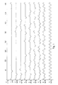
- the diagram in FIG. 1 shows switchable power levels of a hob with a total electrical power of approximately 1800 watts, which is supplied by alternating current at a frequency of 50 Hertz.
- stage 9 with a full power of 100%, the AC voltage is permanently applied, so that it gives the continuous sine curve of the AC current as a waveform.
- FIG. 2 shows the waiting time according to the European standard EN 60 555 part 3 (according to DIN VDE 838, part 3), which must be observed at least between two relative switching voltage changes in order to avoid the so-called flicker effect. Areas below the curve are permissible areas, while areas above the curve are prohibited because they can cause the flicker effect.
- Stage 8 with 66% is achieved by means of a two-third clocking, in which a half-wave is faded out from three half-waves, by virtue of the fact that three half-waves each leave a full wave with positive and negative half-waves, a DC component is avoided.
- a level with 50% performance is not shown, since it is not necessary for the other grading of the hob used. In principle, however, it could be obtained by full wave control, in which a full wave is alternately hidden and the subsequent full wave is let through.
- Level 7 with 40% power is achieved by 1/3 timing with the suppression of another half-wave of the following full wave. There are pause times of 10 and 20 msec, which are within the time up to which two changes in the same direction are regarded as a single change. This power level could also be achieved by a 3/5 half-wave control, in which a full wave is passed through in succession and three half-waves are masked out.
- Level 6 with 33% is achieved by a one-third clocking, in which only one half-wave is passed through from three half-waves. These controls also ensure that they are free of direct current, as can be seen from FIG. 1.
- Stage 5 with 25% power is achieved according to the invention by one-third clocking with additional suppression of a solid wave. After two one-third clocking full periods (six half-periods of the AC voltage), one full period of the AC voltage is faded out. DC freedom is ensured. The blanking time of an additional full period of the output frequency results in switching distances, which are in time ranges within which shifting operations in the same direction are regarded as a single change.
- Level 4 with an output of 17% is obtained by means of a 1/5 cycle combined with additional switch-off times.
- the fade-out times of half-waves of the AC voltage caused by the 1/5 clocking themselves are in the times within which changes are considered as individual, while the additional switch-off leads to a switch-off time of 80 msec, which is above the flicker curve of the standard EN 60 555 :
- the flicker curve is defined up to a relative voltage change of 0.3%, at which the "waiting times" should be over 60 msec, which corresponds to the above. Value is easily met. Moreover, the limit "waiting time” of 60 msec also gives practically the time within which two changes in the same direction are perceived as one, while the value specified in the standard is actually too short.
- stage 3 with a power of 10%, three full periods of one-third clocking are combined with a subsequent switch-off of 220 ms.
- the one-third cycle requires an output power of 600 W (1/3 of the maximum power). This corresponds to a current of 2.6 A and thus a voltage change of absolutely 1.04 volts or relatively 0.45% due to the internal resistance of the network of 0.4 ohms, which is shown in curve 4 b of the EN 60 555 part 3 results in a waiting time of 110-120 msec. The actual waiting time is longer than this, so that the norm is observed.
- stage 2 with an output of approx.6.6%, two one-third cycle full periods are combined with an additional 240 ms switch-off time. Since the output power is the same as before, flicker problems are also excluded here.
- Stage 1 with 3% power corresponding to 54 W or 100 W for a halogen radiator with usually approx. 3300 W (maximum power) assumes a 1/5 cycle and combines this with a switch-off time of 600 msec, which, like is easy to see, is outside of any flicker problem and moreover is below the times from the switching operations on the radiator by its red connection. Decolorization can be seen when heating or cooling, so that such an adverse impression is avoided. Level 0 denotes the complete switch-off of the hob.
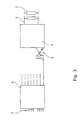
- FIG. 1 designates a power unit in the form of a triac for switching the supply 2 of a connected load 3, such as a hob.
- the power section 1 is controlled by a control section 4 via optocouplers 6.
- the control part 4 has a plurality of corresponding outputs to corresponding optocouplers for different power units, so that the control part 4 can be used to control several consumers, such as hobs.
- the control part 4 receives the information about the desired switching level for the respective hob from switches (not shown), such as BCD switches.
- the switching patterns of the respective power levels can be stored as a bit pattern in a permanent memory such as a ROM, PROM or the like.
- a permanent memory such as a ROM, PROM or the like.
- shift registers by means of which it is achieved that at least when at least two hotplates of a stove are in the same Power stage are operated, the respective (on and off) switching operations carried out by the circuit pattern (bit pattern) are shifted from one another by predetermined delay times (FIG. 5), for example by 10 msec (corresponding to 100 Hz), ie by the time of a half-wave of the mains voltage 4, or multiples thereof.
- the shift register for the hotplate F1 receives the control bit pattern corresponding to the desired power level 5 and gives this without delay to the associated triac 1.1. continue.
- the shift register for hotplate F2 receives the same bit pattern, but gives this to the associated triac 1.2 with a delay of 10 msec.
- the power applied to the hotplate F 2 corresponds to that of the hotplate F 1, but is just shifted by a half-wave (and thus inverted with respect to the times), as can be seen on the right in FIG. 4.
- Your performance may also be delayed by another 10 msec. Insofar as switching operations of different power levels take place simultaneously at certain times, these are permissible according to the standard, since they do not systematically coincide regularly or this happens only from time to time.
- the shift registers of different radiators always and always carry out a different delay of the circuits from radiator to radiator.
- a monitoring device can also be provided which monitors whether one or more radiators are already in one works for another radiator selected power level and then performs a suitable delay.
- Fig. 4 shows a circuit on a (simple 2-wire) AC voltage network.
- this is preferably connected to a multi-phase network (three-phase network) that the hotplates are distributed over different phases, whereby a further The switching times are equalized.
Landscapes
- Chemical & Material Sciences (AREA)
- Engineering & Computer Science (AREA)
- Ceramic Engineering (AREA)
- Control Of Resistance Heating (AREA)
Applications Claiming Priority (2)
| Application Number | Priority Date | Filing Date | Title |
|---|---|---|---|
| DE4004508 | 1990-02-14 | ||
| DE19904004508 DE4004508A1 (de) | 1990-02-14 | 1990-02-14 | Verfahren und vorrichtung zur steuerung der leistung mindestens eines verbrauchers |
Publications (2)
| Publication Number | Publication Date |
|---|---|
| EP0442139A2 true EP0442139A2 (fr) | 1991-08-21 |
| EP0442139A3 EP0442139A3 (en) | 1992-04-15 |
Family
ID=6400107
Family Applications (1)
| Application Number | Title | Priority Date | Filing Date |
|---|---|---|---|
| EP19900125370 Withdrawn EP0442139A3 (en) | 1990-02-14 | 1990-12-22 | Method and device for steering the power of at least one consumer |
Country Status (3)
| Country | Link |
|---|---|
| EP (1) | EP0442139A3 (fr) |
| JP (1) | JPH04218289A (fr) |
| DE (1) | DE4004508A1 (fr) |
Cited By (6)
| Publication number | Priority date | Publication date | Assignee | Title |
|---|---|---|---|---|
| FR2679628A1 (fr) * | 1991-07-23 | 1993-01-29 | Europ Equip Menager | Procede d'alimentation de foyer chauffant et foyer chauffant equipe de sa commande d'alimentation permettant la mise en óoeuvre dudit procede. |
| EP0804049A3 (fr) * | 1996-04-26 | 1998-09-23 | Ceramaspeed Limited | Agencement d'un élément de chauffage électrique rayonnant |
| GB2329769A (en) * | 1997-09-24 | 1999-03-31 | Ceramaspeed Ltd | Electric heater control |
| WO2004028211A1 (fr) * | 2002-09-17 | 2004-04-01 | Günkol Günes Enerjisi Ve Klima San. A.S. | Procede d'economie d'energie pour plaques chauffantes de cuisson a l'electricite |
| EP2887763A1 (fr) | 2013-12-19 | 2015-06-24 | Electrolux Appliances Aktiebolag | Procédé, appareil et produit de programme informatique pour commander une source de chaleur associée à de l'inertie thermique |
| EP2648777B1 (fr) | 2010-12-09 | 2018-02-07 | Fresenius Medical Care Deutschland GmbH | Appareil médical équipé d'un chauffage |
Families Citing this family (4)
| Publication number | Priority date | Publication date | Assignee | Title |
|---|---|---|---|---|
| DE4309031A1 (de) * | 1992-03-30 | 1993-10-21 | Licentia Gmbh | Verfahren zum Betreiben mehrerer parallel geschalteter Thyristorsteller |
| DE10129170A1 (de) * | 2001-06-12 | 2002-12-19 | Ego Elektro Geraetebau Gmbh | Verfahren zur Steuerung der Leistung einer elektrischen Heizeinrichtung |
| DE102012209385A1 (de) * | 2012-06-04 | 2013-12-05 | Zf Friedrichshafen Ag | Verfahren und Vorrichtung zum Steuern eines Heizgeräts und Heizgerät |
| DE102016109244B4 (de) | 2016-05-19 | 2019-07-04 | Océ Holding B.V. | Trocknungseinheit für ein Tintenstrahl-Drucksystem mit Halbwellen-symmetrischem Betrieb |
Family Cites Families (14)
| Publication number | Priority date | Publication date | Assignee | Title |
|---|---|---|---|---|
| JPS5069542A (fr) * | 1973-07-19 | 1975-06-10 | ||
| DE2836882C2 (de) * | 1978-08-23 | 1986-08-14 | E.G.O. Elektro-Geräte AG, Zug | Steuergerät für Elektrokochplatten |
| DE2837934A1 (de) * | 1978-08-31 | 1980-03-06 | Eckerfeld Geb Reip Elisabeth | Vorrichtung zur regelung der auslauftemperatur bei elektrischen durchlauferhitzern |
| US4282422A (en) * | 1979-02-01 | 1981-08-04 | General Electric Company | Power control for appliance using multiple high inrush current elements |
| DE3164856D1 (en) * | 1980-05-08 | 1984-08-23 | Lucas Ind Plc | Switching system for sequential connection of loads to an electrical supply |
| US4404461A (en) * | 1980-09-24 | 1983-09-13 | Leco Corporation | Method and apparatus for controlling an analytical furnace |
| AT382282B (de) * | 1983-10-04 | 1987-02-10 | Burg Konrad Fa | Schaltungsanordnung zur regelung der heizleistung eines heizluefters |
| DE3437242A1 (de) * | 1984-10-11 | 1986-04-17 | Alfred 5628 Heiligenhaus Eckerfeld | Elektronischer leistungssteller, insbesondere zur regelung der auslauftemperatur bei elektrischen durchlauferhitzern |
| GB8432542D0 (en) * | 1984-12-21 | 1985-02-06 | Micropore International Ltd | Power control arrangement |
| DE3539581A1 (de) * | 1985-11-08 | 1987-05-21 | Philips Patentverwaltung | Verfahren zum steuern mehrerer elektrischer lasten |
| GB8527683D0 (en) * | 1985-11-09 | 1985-12-11 | Thorn Emi Appliances | Control circuit |
| US4859832A (en) * | 1986-09-08 | 1989-08-22 | Nikon Corporation | Light radiation apparatus |
| US4786799A (en) * | 1987-07-27 | 1988-11-22 | General Electric Company | Power control for cooking appliance with multiple heating units |
| DE3834433A1 (de) * | 1987-10-23 | 1989-05-03 | Burg Konrad Fa | Verfahren zur leistungssteuerung eines heizluefters und schaltungsanordnung hierfuer |
-
1990
- 1990-02-14 DE DE19904004508 patent/DE4004508A1/de not_active Withdrawn
- 1990-12-22 EP EP19900125370 patent/EP0442139A3/de not_active Withdrawn
-
1991
- 1991-02-12 JP JP1881191A patent/JPH04218289A/ja active Pending
Cited By (9)
| Publication number | Priority date | Publication date | Assignee | Title |
|---|---|---|---|---|
| FR2679628A1 (fr) * | 1991-07-23 | 1993-01-29 | Europ Equip Menager | Procede d'alimentation de foyer chauffant et foyer chauffant equipe de sa commande d'alimentation permettant la mise en óoeuvre dudit procede. |
| EP0804049A3 (fr) * | 1996-04-26 | 1998-09-23 | Ceramaspeed Limited | Agencement d'un élément de chauffage électrique rayonnant |
| US5908571A (en) * | 1996-04-26 | 1999-06-01 | Ceramaspeed Limited | Radiant electric heater arrangement |
| GB2329769A (en) * | 1997-09-24 | 1999-03-31 | Ceramaspeed Ltd | Electric heater control |
| EP0906000A3 (fr) * | 1997-09-24 | 1999-08-25 | Ceramaspeed Limited | Appareil pour contrÔler un chauffage électrique |
| US6118106A (en) * | 1997-09-24 | 2000-09-12 | Ceramaspeed Limited | Apparatus for controlling an electric heater energized from a single voltage alternating current supply |
| WO2004028211A1 (fr) * | 2002-09-17 | 2004-04-01 | Günkol Günes Enerjisi Ve Klima San. A.S. | Procede d'economie d'energie pour plaques chauffantes de cuisson a l'electricite |
| EP2648777B1 (fr) | 2010-12-09 | 2018-02-07 | Fresenius Medical Care Deutschland GmbH | Appareil médical équipé d'un chauffage |
| EP2887763A1 (fr) | 2013-12-19 | 2015-06-24 | Electrolux Appliances Aktiebolag | Procédé, appareil et produit de programme informatique pour commander une source de chaleur associée à de l'inertie thermique |
Also Published As
| Publication number | Publication date |
|---|---|
| EP0442139A3 (en) | 1992-04-15 |
| JPH04218289A (ja) | 1992-08-07 |
| DE4004508A1 (de) | 1991-08-22 |
Similar Documents
| Publication | Publication Date | Title |
|---|---|---|
| DE60124760T2 (de) | Hybride elektrische schalteinrichtung | |
| DE4332059B4 (de) | Vorschaltgerät zur Helligkeitssteuerung von Entladungslampen | |
| DE2922085A1 (de) | Mikrowellen-koch- oder -backgeraet | |
| DE2505453A1 (de) | Helligkeitssteuerungsschaltung | |
| EP0677917A2 (fr) | Disposition de circuit avec un onduleur | |
| EP0442139A2 (fr) | Procédé et dispositif de commande de la puissance d'au moins un consommateur | |
| DE3726535A1 (de) | Verfahren zur schaltstossarmen leistungssteuerung elektrischer lasten | |
| DE3601555C2 (fr) | ||
| DE69502294T2 (de) | Verfahren und schaltungsanordnung zur leistungssteuerung einer last durch ein phasensteuerungssystem | |
| DE10315554B3 (de) | Dimmer Booster | |
| DE69806213T2 (de) | Vorrichtung zur Regelung einer elektrischen Heizung | |
| CH690891A5 (de) | Heizleistungsregulierung für Induktionskochherd. | |
| DE3540830A1 (de) | Verfahren zum stufenweisen einstellen einer an einem an spannung ueber einen schalter liegenden widerstand anfallenden elektrischen leistung und schaltungsanordnung zur durchfuehrung des verfahrens | |
| EP1494505B1 (fr) | Méthode et dispositif de régulation de puissance pour plaques à inductions | |
| DE19900185A1 (de) | Verfahren und Vorrichtung zum Schalten von Verbrauchern eines Elektrogerätes | |
| DE2517211C2 (de) | Schaltung zur Helligkeitssteuerung von Gasentladungslampen | |
| DE102012201237A1 (de) | Hausgerätevorrichtung | |
| EP3664578B1 (fr) | Dispositif formant appareil de cuisson | |
| DE19738890A1 (de) | Verfahren zur schaltstoßarmen Leistungssteuerung elektrischer Lasten sowie elektrisches Heizgerät | |
| DE4336973A1 (de) | Elektrischer Leistungssteller | |
| DE2155633A1 (de) | Mit mikrowellenenergie beheizte ofenanlage | |
| DE3541091C2 (fr) | ||
| EP0201573B1 (fr) | Procede pour le reglage par paliers du courant present sur une resistance liee a une tension a travers un interrupteur, et arrangement de circuit pour la mise en oeuvre du procede | |
| DE10160912B4 (de) | Verfahren und Einrichtung zur Steuerung des von mindestens zwei elektrischen Verbrauchern gleicher Leistungsaufnahme, insbesondere Heizkörpern, aufgenommenen Wechselstroms | |
| DE3645189C2 (en) | Three=phase continuous flow water heater |
Legal Events
| Date | Code | Title | Description |
|---|---|---|---|
| PUAI | Public reference made under article 153(3) epc to a published international application that has entered the european phase |
Free format text: ORIGINAL CODE: 0009012 |
|
| AK | Designated contracting states |
Kind code of ref document: A2 Designated state(s): CH DE FR GB IT LI SE |
|
| PUAL | Search report despatched |
Free format text: ORIGINAL CODE: 0009013 |
|
| AK | Designated contracting states |
Kind code of ref document: A3 Designated state(s): CH DE FR GB IT LI SE |
|
| 17P | Request for examination filed |
Effective date: 19920410 |
|
| 17Q | First examination report despatched |
Effective date: 19931012 |
|
| STAA | Information on the status of an ep patent application or granted ep patent |
Free format text: STATUS: THE APPLICATION IS DEEMED TO BE WITHDRAWN |
|
| 18D | Application deemed to be withdrawn |
Effective date: 19940223 |