EP0442151A2 - Combination light unit and battery monitor device - Google Patents
Combination light unit and battery monitor device Download PDFInfo
- Publication number
- EP0442151A2 EP0442151A2 EP90125796A EP90125796A EP0442151A2 EP 0442151 A2 EP0442151 A2 EP 0442151A2 EP 90125796 A EP90125796 A EP 90125796A EP 90125796 A EP90125796 A EP 90125796A EP 0442151 A2 EP0442151 A2 EP 0442151A2
- Authority
- EP
- European Patent Office
- Prior art keywords
- battery
- voltage
- indicating
- load
- charge
- Prior art date
- Legal status (The legal status is an assumption and is not a legal conclusion. Google has not performed a legal analysis and makes no representation as to the accuracy of the status listed.)
- Withdrawn
Links
Images

Classifications
-
- G—PHYSICS
- G01—MEASURING; TESTING
- G01R—MEASURING ELECTRIC VARIABLES; MEASURING MAGNETIC VARIABLES
- G01R31/00—Arrangements for testing electric properties; Arrangements for locating electric faults; Arrangements for electrical testing characterised by what is being tested not provided for elsewhere
- G01R31/36—Arrangements for testing, measuring or monitoring the electrical condition of accumulators or electric batteries, e.g. capacity or state of charge [SoC]
- G01R31/3644—Constructional arrangements
- G01R31/3648—Constructional arrangements comprising digital calculation means, e.g. for performing an algorithm
-
- G—PHYSICS
- G01—MEASURING; TESTING
- G01R—MEASURING ELECTRIC VARIABLES; MEASURING MAGNETIC VARIABLES
- G01R15/00—Details of measuring arrangements of the types provided for in groups G01R17/00 - G01R29/00, G01R33/00 - G01R33/26 or G01R35/00
- G01R15/04—Voltage dividers
-
- G—PHYSICS
- G01—MEASURING; TESTING
- G01R—MEASURING ELECTRIC VARIABLES; MEASURING MAGNETIC VARIABLES
- G01R19/00—Arrangements for measuring currents or voltages or for indicating presence or sign thereof
- G01R19/165—Indicating that current or voltage is either above or below a predetermined value or within or outside a predetermined range of values
- G01R19/16533—Indicating that current or voltage is either above or below a predetermined value or within or outside a predetermined range of values characterised by the application
- G01R19/16538—Indicating that current or voltage is either above or below a predetermined value or within or outside a predetermined range of values characterised by the application in AC or DC supplies
- G01R19/16542—Indicating that current or voltage is either above or below a predetermined value or within or outside a predetermined range of values characterised by the application in AC or DC supplies for batteries
-
- Y—GENERAL TAGGING OF NEW TECHNOLOGICAL DEVELOPMENTS; GENERAL TAGGING OF CROSS-SECTIONAL TECHNOLOGIES SPANNING OVER SEVERAL SECTIONS OF THE IPC; TECHNICAL SUBJECTS COVERED BY FORMER USPC CROSS-REFERENCE ART COLLECTIONS [XRACs] AND DIGESTS
- Y10—TECHNICAL SUBJECTS COVERED BY FORMER USPC
- Y10S—TECHNICAL SUBJECTS COVERED BY FORMER USPC CROSS-REFERENCE ART COLLECTIONS [XRACs] AND DIGESTS
- Y10S320/00—Electricity: battery or capacitor charging or discharging
- Y10S320/18—Indicator or display
- Y10S320/21—State of charge of battery
Definitions
- This invention relates to a combination light unit and battery monitor device and more particularly to a device usable with video cameras or camcorders or the like and which is comparatively simple and inexpensive but which is readily operable to obtain reliable indications as to the status of charge of a which is battery used to energize one or more lights and which may also be used for operation of the video camera or camcorder.
- the prior art includes a great many disclosures of devices for monitoring the status of charge of various forms of batteries but so far as is known, none of the devices as used or proposed in the prior art have been entirely suitable and satisfactory for reliable monitoring of the condition of charge of batteries such as used in video cameras or camcorders or in light units for use therewith.
- This invention was evolved with the general object of providing a battery monitor device which is highly reliable and readily used while being inexpensively manufacturable.
- An important aspect of the invention relates to the recognition that a lamp such as is usable for a battery operated video camera or camcorder provides a load which has a predetermined relatively low resistance and which can be used to load down a battery to obtain a accurate and reliable indication of the condition of charge of a battery and particularly that of a nickel cadmium or "NiCAD" or a battery of similar characteristics.
- the no-load voltage is substantially constance and the output voltage under light load conditions decreases only very gradually so that it is not possible to obtain a reliable indication of battery conditions through measurement of battery voltage under light load conditions.
- a lamp is used to provide a load of known resistance for measurement of the condition of charge of a battery and a comparatively simple and yet highly reliable indicating arrangement is provided, preferably including light-emitting diodes, differential amplifies and reference voltage sources such as provided by Zener diodes.
- a specific feature relates to the indication both of a certain safely discharged condition in which the battery should be discharged and the approach of such condition to alert the user of the impending need for a recharging operation.
- This feature is realized through the provision of two indicating lights and/or through the use of two selectively operable loads such as provided by two lamps of different wattage ratings. Both can be used to permit the user to accurately measure the charge condition and to avoid the a needless recharge of the battery while at the same time insuring that a recharge will be effected when actually necessary.
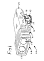
- Reference numeral 10 generally designates a combination light unit and battery monitor device which is constructed in accordance with the principles of this invention.
- the illustrated device 10 includes a base structure 11 having a depending mounting foot 12 for mounting on a video camera or camcorder, using a knurled mounting lock ring 13.
- a lamp structure 14 is secured on a forward end of the base structure 11 and includes two lamps 15 and 16.
- the lamp structure 14 preferably includes a plurality of open slots for ventilation to dissipate the heat generated by the lamps 15 and 16.
- Lamps 15 and 16 may preferably have different wattages, for example, ten watts and twenty watts, and are controlled by a pair of switches 17 and 18 on the depending mounting foot 12. Three levels of illumination are thus obtained depending upon operation of one or the other of the switches 17 and 18 alone or operation of both together.
- the lamps of the device may be energized from a battery of a video camera or camcorder or similar equipment with which the lamps are used and battery monitoring circuitry of the device may be used to monitor the condition of charge of such a battery.
- the base structure 11 of the illustrated device is arranged to releasably receive a battery pack 20 for energization of the lamps and the monitoring circuitry is used to monitor its condition.
- a release button is provided on the rear of the base structure 11 for release of the battery pack 20 so that it can be recharged when necessary.
- Three indicating lights 21, 22 and 23 are provided on the side of the base structure 11, above the switches 17 and 18. When the battery is fully charged, and either or both of the switches 17 or 18 is operated, all three indicator lights 21-23 are energized. When the battery is less than fully charged, either or both of the lights 22 and 23 may be deenergized, depending upon the level of charge and depending upon the actuation of the switches 17 and 18.
- the deenergization of both lamps 22 and 23 may indicate that the level of charge is decreased to a safely discharged condition such that the battery should be recharged.
- the indicator lights 21, 22 and 23 may be used in connection with the switches 17 and 18 to determine the approximate level of charge of the battery and to indicate the approach of a safely discharged condition at which the battery should be recharged. This feature is important since it is generally desirable to recharge the battery only after it has been discharged to a substantial extent.
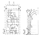
- FIG. 2 is a diagram of electrical circuitry of the device 10.
- a battery 24 of the battery pack 20 is connected to a pair of terminals 25 and 26 which are engaged with terminals 27 and 28 when the battery pack 20 is installed, the terminals 25 and 26 being physically located on the underside of the battery pack while the terminals 27 and 28 may preferably be spring-urged terminals located on the upper side of the base structure 11.
- suitable terminals may be provided in a mounting foot of the device, to engage terminals of a mounting shoe which are connectable to the battery of the video camera or camcorder.
- terminal 27 is connected through switches 17 and 18 to terminals of the lamps 15 and 16, the other terminals of lamps 15 and 16 being connected to the terminal 28.
- the junctions between lamps 15 and 16 and the switches 17 and 18 are connected through diodes 29 and 30 to the conductor 32 so that a positive voltage is developed at conductor 32 relative to the terminal 28 when either of the switches 17 and 18 is closed.
- Connector 32 is connected through a resistor 33 and the indicator light 21 to the terminal 28, the indicator 28 being preferably a LED, as indicated schematically.
- Conductor 32 is also connected through resistors 35 and 36 and through the lights 22 and 23 to outputs of two differential amplifiers 37 and 38.
- Minus inputs of the amplifiers 37 and 38 are connected to a reference voltage source which is provided by a Zener diode 40 connected in series with a resistor 41 between the terminal 28 and the conductor 32.
- the plus input of differential amplifier 37 is connected to a voltage divider formed by resistors 43 and 44 while the plus input of amplifier 38 is connected to a voltage divider formed by resistors 45 and 46, both voltage dividers being connected between terminal 28 and the conductor 32.
- the values of the resistances of the two voltage dividers in relation to the reference voltage provided by the Zener diode 40 are such as to establish a first voltage level which is less than the no-load voltage of the battery 24 and to establish a second level which is still lower than the no-load voltage of the battery 24.
- the no-load voltage may be 6.0 volts
- the first level may be 5.7 volts
- the third level may be 5.3 volts.
- the amplifier 37 is switched to deenergize the indicator light 22.
- the amplifier 38 is switched to deenergize the indicator light 23.
- FIG. 3 is a plot illustrating the type of operation obtained with the illustrated circuit.
- Dashed line 48 indicates the no-load voltage of the battery which may be six volts, for example.
- Dashed line 49 indicates the aforementioned first level and broken line 50 indicates the aforementioned second level.
- the battery voltage is plotted against battery charge depletion with three different levels of load. In each case the voltage decreases at a relatively gradual rate until the charge reaches the lowest level which is normally safe for effecting a discharge. Beyond that level, the voltage drops precipitously.
- Curve 51 illustrates the characteristic with a first load applied to the battery which may, for example, be the load provided when only the ten watt lamp 15 is energized.
- Curve 52 shows the characteristic with a higher load which may, for example, be that with only the twenty watt lamp 16 energized.
- Curve 53 shows the characteristic with a still higher load such as with both lamps 15 and 16 energized.
- the operational characteristics such as depicted in Figure 3 may be used in a variety of ways for monitoring the condition of charge of the battery 24.
- the battery voltage drops below the first level 49 at a point 57, to deenergize the light 22 and drops below the second level 50 at a point 58 to deenergize the light 23.
- the deenergization of the light 22 at the point 56 indicates to the user that the battery is less than fully charged and that the conditions are approaching the condition at which the battery should be recharged.
- light 23 is deenergized, and with only lamp 15 energized, it indicates to the user that the battery should be recharged.
- both lamps 15 and 16 results in deenergization of both indicating lights 22 and 23, it is established that the charge has been depleted beyond a level corresponding to point 62, but if with lamp 16 alone energized, the light 23 remains energized, it is established that the charge has nor been depleted beyond a level corresponding to point 60 and that a charge is available for continued operation, especially if the load is light as when only lamp 15 is to be energized.
- FIG 4 illustrates a modification which uses certain of the same components shown in Figure 2, but in which only a single lamp 64 is shown connected through a switch 66 to terminals 67 and 68 for connection to the battery terminals 25 and 26 to be energized from the battery 24.
- the battery 24 in this case may be that of a video camera or camcorder on which the device is mounted and, as indicated by plus and minus signs adjacent terminals 25 and 26, the battery may be of either polarity.
- the terminals of the lamp 64 are connected to input terminals of a bridge rectifier 70 having positive and negative output terminals 71 and 72 for supplying an operating voltage to indicating circuitry.
- the light 21 is connected through a resistor 33 to the positive and negative terminals 71 and 72 and the lights 22 and 23 are connected in circuit with the amplifiers 37 and 38 and associated resistors and voltage dividers in the same manner as shown in Figure 2.
- the plus input terminals of the amplifiers 37 and 38 are connected to a reference voltage source which is adjustable, a movable contact of a switch 74 being connected through a resistor 75 to the positive output terminal 71 of the bridge rectifier 70, and being selectively connectable through three Zener diodes 76, 77 and 78 to the negative terminal 72 of the bridge rectifier 70.
- the circuitry is usable with batteries of opposite polarity.
- the device may be used with different types of batteries.
- the Zener diode 76 may be used to provide a reference suitable for batteries having a no-load voltage of six volts, such as those used in the Sony, Canon, Sanyo, and other camcorders
- the diode 77 may be used to provide a reference suitable for batteries having a no-load voltage of 7.2 volts such as those used in the Hitachi, Minolta and Pentax camcorders
- the diode 78 may be used to provide a reference suitable for batteries having a no-load voltage of 9.6 volts, such as used in Panasonic and JVC camcorders.
Landscapes
- Physics & Mathematics (AREA)
- General Physics & Mathematics (AREA)
- Charge And Discharge Circuits For Batteries Or The Like (AREA)
Abstract
Description
- This invention relates to a combination light unit and battery monitor device and more particularly to a device usable with video cameras or camcorders or the like and which is comparatively simple and inexpensive but which is readily operable to obtain reliable indications as to the status of charge of a which is battery used to energize one or more lights and which may also be used for operation of the video camera or camcorder.
- The prior art includes a great many disclosures of devices for monitoring the status of charge of various forms of batteries but so far as is known, none of the devices as used or proposed in the prior art have been entirely suitable and satisfactory for reliable monitoring of the condition of charge of batteries such as used in video cameras or camcorders or in light units for use therewith.
- This invention was evolved with the general object of providing a battery monitor device which is highly reliable and readily used while being inexpensively manufacturable.
- An important aspect of the invention relates to the recognition that a lamp such as is usable for a battery operated video camera or camcorder provides a load which has a predetermined relatively low resistance and which can be used to load down a battery to obtain a accurate and reliable indication of the condition of charge of a battery and particularly that of a nickel cadmium or "NiCAD" or a battery of similar characteristics. In such a battery, the no-load voltage is substantially constance and the output voltage under light load conditions decreases only very gradually so that it is not possible to obtain a reliable indication of battery conditions through measurement of battery voltage under light load conditions. However, if a higher load is applied and especially if it is a higher load operative as a resistance of known value, such as is provided by a lamp, it is found to be possible to obtain a highly accurate and reliable indication of the condition of charge of a battery.
- In accordance with the invention, a lamp is used to provide a load of known resistance for measurement of the condition of charge of a battery and a comparatively simple and yet highly reliable indicating arrangement is provided, preferably including light-emitting diodes, differential amplifies and reference voltage sources such as provided by Zener diodes.
- A specific feature relates to the indication both of a certain safely discharged condition in which the battery should be discharged and the approach of such condition to alert the user of the impending need for a recharging operation. This feature is realized through the provision of two indicating lights and/or through the use of two selectively operable loads such as provided by two lamps of different wattage ratings. Both can be used to permit the user to accurately measure the charge condition and to avoid the a needless recharge of the battery while at the same time insuring that a recharge will be effected when actually necessary.
- Further features relate to the use of a bridge rectifier for operable of the device with batteries of opposite polarity and to the provision of selective means for operation with batteries of different characteristics.
- This invention contemplates other objects, features and advantages which will become more fully apparent from the following detailed description taken in conjunction with the accompanying drawings.
-
- FIGURE 1 is a perspective view of a combination light unit and battery monitor device of the invention;
- FIGURE 2 is a diagram of circuitry of the device of FIG. 1;
- FIGURE 3 is a graph illustrating characteristics of a battery of a type which can be monitored, for explanation of the invention; and
- FIGURE 4 is a diagram of modified circuitry according to the invention.
-
Reference numeral 10 generally designates a combination light unit and battery monitor device which is constructed in accordance with the principles of this invention. The illustrateddevice 10 includes a base structure 11 having a depending mountingfoot 12 for mounting on a video camera or camcorder, using a knurledmounting lock ring 13. - A
lamp structure 14 is secured on a forward end of the base structure 11 and includes twolamps lamp structure 14 preferably includes a plurality of open slots for ventilation to dissipate the heat generated by thelamps Lamps switches foot 12. Three levels of illumination are thus obtained depending upon operation of one or the other of theswitches - The lamps of the device may be energized from a battery of a video camera or camcorder or similar equipment with which the lamps are used and battery monitoring circuitry of the device may be used to monitor the condition of charge of such a battery. However, the base structure 11 of the illustrated device is arranged to releasably receive a
battery pack 20 for energization of the lamps and the monitoring circuitry is used to monitor its condition. A release button, not shown, is provided on the rear of the base structure 11 for release of thebattery pack 20 so that it can be recharged when necessary. - Three indicating
lights switches switches lights switches - For example, with
switch 18 operated to energize the twentywatt lamp 16, the deenergization of bothlamps indicator lights switches - Figure 2 is a diagram of electrical circuitry of the
device 10. As shown, abattery 24 of thebattery pack 20 is connected to a pair ofterminals terminals battery pack 20 is installed, theterminals terminals - As shown,
terminal 27 is connected throughswitches lamps lamps terminal 28. The junctions betweenlamps switches diodes conductor 32 so that a positive voltage is developed atconductor 32 relative to theterminal 28 when either of theswitches Connector 32 is connected through aresistor 33 and theindicator light 21 to theterminal 28, theindicator 28 being preferably a LED, as indicated schematically. -
Conductor 32 is also connected throughresistors lights differential amplifiers amplifiers diode 40 connected in series with a resistor 41 between theterminal 28 and theconductor 32. - The plus input of
differential amplifier 37 is connected to a voltage divider formed byresistors amplifier 38 is connected to a voltage divider formed byresistors terminal 28 and theconductor 32. The values of the resistances of the two voltage dividers in relation to the reference voltage provided by theZener diode 40 are such as to establish a first voltage level which is less than the no-load voltage of thebattery 24 and to establish a second level which is still lower than the no-load voltage of thebattery 24. - For example, the no-load voltage may be 6.0 volts, the first level may be 5.7 volts and the third level may be 5.3 volts. When the voltage drops below the first level, the
amplifier 37 is switched to deenergize theindicator light 22. When the voltage is below the second level, theamplifier 38 is switched to deenergize theindicator light 23. - Figure 3 is a plot illustrating the type of operation obtained with the illustrated circuit. Dashed
line 48 indicates the no-load voltage of the battery which may be six volts, for example. Dashedline 49 indicates the aforementioned first level andbroken line 50 indicates the aforementioned second level. - The battery voltage is plotted against battery charge depletion with three different levels of load. In each case the voltage decreases at a relatively gradual rate until the charge reaches the lowest level which is normally safe for effecting a discharge. Beyond that level, the voltage drops precipitously.
Curve 51 illustrates the characteristic with a first load applied to the battery which may, for example, be the load provided when only the tenwatt lamp 15 is energized.Curve 52 shows the characteristic with a higher load which may, for example, be that with only the twentywatt lamp 16 energized.Curve 53 shows the characteristic with a still higher load such as with bothlamps - The operational characteristics such as depicted in Figure 3 may be used in a variety of ways for monitoring the condition of charge of the
battery 24. For example, using only the tenwatt lamp 15, the battery voltage drops below thefirst level 49 at apoint 57, to deenergize thelight 22 and drops below thesecond level 50 at apoint 58 to deenergize thelight 23. Thus, using only thelamp 15, the deenergization of thelight 22 at the point 56 indicates to the user that the battery is less than fully charged and that the conditions are approaching the condition at which the battery should be recharged. Then, whenlight 23 is deenergized, and with onlylamp 15 energized, it indicates to the user that the battery should be recharged. - Similarly, there are two
points curve 52 which correspond topoints curve 51 and twopoints 61 and 62 oncurve 53 which correspond topoints curve 51. These may be used in a variety of ways. For example, if both indicatinglights lamps lamps lights lamp 16 alone energized, the light 23 remains energized, it is established that the charge has nor been depleted beyond a level corresponding to point 60 and that a charge is available for continued operation, especially if the load is light as whenonly lamp 15 is to be energized. - Figure 4 illustrates a modification which uses certain of the same components shown in Figure 2, but in which only a single lamp 64 is shown connected through a
switch 66 toterminals battery terminals battery 24. Thebattery 24 in this case may be that of a video camera or camcorder on which the device is mounted and, as indicated by plus and minus signsadjacent terminals negative output terminals 71 and 72 for supplying an operating voltage to indicating circuitry. - The light 21 is connected through a
resistor 33 to the positive andnegative terminals 71 and 72 and thelights amplifiers amplifiers switch 74 being connected through aresistor 75 to thepositive output terminal 71 of the bridge rectifier 70, and being selectively connectable through threeZener diodes - With the bridge rectifier 70 as shown, the circuitry is usable with batteries of opposite polarity. With the use of the selectable reference voltage levels, the device may be used with different types of batteries. For example, the
Zener diode 76 may be used to provide a reference suitable for batteries having a no-load voltage of six volts, such as those used in the Sony, Canon, Sanyo, and other camcorders, thediode 77 may be used to provide a reference suitable for batteries having a no-load voltage of 7.2 volts such as those used in the Hitachi, Minolta and Pentax camcorders and the diode 78 may be used to provide a reference suitable for batteries having a no-load voltage of 9.6 volts, such as used in Panasonic and JVC camcorders. - It will be understood that although only a single lamp 64 is shown in Figure 4, the features illustrated in this diagram may be used with a device having two or more lamps.
- It will be understood that other modifications and variations may be effected without departing from the spirit and scope of the novel concepts of this invention
Claims (19)
- A combination light unit and battery monitor device for use with a video camera or the like and operable by a type of battery having certain no-load output voltage and charge characteristics such that as its charge is depleted from a charged condition its output voltage with a load resistance connected thereto is gradually reduced to drop well below said no-load voltage and reach a safe voltage when in a safely discharged condition and to thereafter drop precipitously when said charge is depleted beyond said safely discharged condition, said safe voltage being a function of said load resistance, said device comprising: a pair of input terminal means for interconnection to a pair of terminals of said battery, light means for illumination of objects in a field of view of said camera and providing at least one predetermined value of load resistance, connecting means between said light means and said input terminal means for connecting said light means in parallel with said battery for energization therefrom, and battery charge condition indicating means connected in parallel relation to said light means for monitoring the battery voltage applied from said battery to said light means, said battery charge condition indicating means being arranged to indicate when the voltage across said light means has dropped below a certain voltage which is equal to said safe voltage as determined by the said predetermined value of load resistance provided by said light means.
- A combination light unit and battery monitor device as defined in claim 1, wherein said battery charge condition indicating means is arranged to provide an indication of the approach of a safely discharged condition of said battery.
- A combination light unit and battery monitor device as defined in claim 2, wherein said battery charge indicating means is arranged to indicate when said battery voltage has dropped below an intermediate voltage which is less than said no-load voltage and higher than said certain voltage to provide said indication of the approach of a discharged condition of said battery.
- A combination light unit and battery monitor device as defined in claim 2, having first and second modes of operation, said light means including at least two light means and being arranged to operate in said first mode to provide a low level of illumination and a first predetermined value of load resistance and in said second mode to provide a higher level of illumination and a second predetermined value of load resistance lower that said first predetermined value of load resistance, said battery charge condition indicating means being arranged to operate in said first mode to indicate when the voltage across said light means has dropped below a certain voltage which is equal to said safe voltage as determined by said first predetermined value of load resistance and in said second mode to again indicate when the voltage across said light means has dropped below said certain voltage to provide said indication of said approach of a safe discharged condition of said battery.
- A combination light unit and battery monitor device as defined in claim 3, wherein said battery charge condition indicating means includes a first indicating light for indicating when said battery voltage has dropped to less than said intermediate voltage and a second indicating light for indicating when said battery voltage has dropped to below said safe voltage.
- A combination light unit and battery monitor device as defined in claim 5, wherein both said first and second indicating lights are energized when said battery voltage is above said intermediate voltage, said first indicating light is deenergized when said battery voltage has dropped to less than said intermediate voltage and said second indicating light is deenergized when said battery voltage has dropped to less than said certain voltage.
- A combination light unit and battery monitor device as defined in claim 6, including a third indicating light which is energized when said battery voltage is applied to said input terminal means.
- A combination light unit and battery monitor device as defined in claim 6, wherein said each of said indicating lights is a LED and wherein said battery charge indicating means further includes first and second differential amplifiers having output terminals connected to said first and second indicting lights and each having first and second input terminals, reference voltage means coupled to said input terminals and connected to said first terminals of both of said differential amplifiers to supply a substantially constant reference voltage thereto, and first and second voltage divider means coupled to said input terminals and respectively connected to said second input terminals of said first and second differential amplifiers.
- A combination light unit and battery monitor device as defined in claim 1, arranged for selective operation with a second type of battery having a no-load output voltage differing substantially from that of the first type of battery and having charge characteristics similar to those of the first type of battery but such as to have safe voltage differing substantially from that of the first type of battery, said device further including selection means for selectively setting said battery charge condition indicating means for indicating drops below different safe voltages according to whether the first or second type of battery is in use.
- A combination light unit and battery monitor device as defined in claim 1, wherein said battery charge indicating means is operable independently of the polarity of connection of said input terminal means to said battery.
- A combination light unit and battery monitor device as defined in claim 10, wherein said battery charge indicating means includes circuitry requiring an operating voltage of one polarity for operation, and further includes a bridge rectifier between said circuitry and said input terminal means.
- A battery monitor device for equipment operable by a type of battery having certain no-load output voltage and charge characteristics such that as its charge is depleted from a charged condition its output voltage with a load resistance connected thereto is gradually reduced to drop well below said no-load voltage and reach a safe voltage when in a safely discharged condition and to thereafter drop precipitously when said charge is depleted beyond said safely discharged condition, said safe voltage being a function of the value of said load resistance, said device comprising: input terminal means for interconnection to terminals of said battery, load means for providing a predetermined load resistance, connecting means between said load means and said input terminal means for connecting said load means in parallel with said battery for energization therefrom, and battery charge condition indicating means connected in parallel relation to said load means for monitoring the battery voltage applied from said battery to said load means, said battery charge condition indicating means being arranged to indicate when the voltage across said load means has dropped to below a certain value which is equal to said safe voltage as determined by said predetermined load resistance and to indicate when said battery voltage has dropped below an intermediate voltage which is less than said no-load voltage and higher than said safe voltage to indicate the approach of a discharged condition of said battery.
- A battery monitor device as defined in claim 12, wherein said battery charge condition indicating means includes a first indicating light for indicating when said battery voltage has dropped to less than said intermediate voltage and a second indicating light for indicating when said battery voltage has dropped to below said certain voltage, and wherein both said first and second indicating lights are energized when said battery voltage is above said intermediate voltage, said first indicating light is deenergized when said battery voltage has dropped to less than said intermediate voltage and said second indicating light is deenergized when said battery voltage has dropped to less than said certain voltage.
- A combination light unit and battery monitor device as defined in claim 13, including a third indicating light which is energized when said battery voltage is applied to said input terminal means.
- A combination light unit and battery monitor device as defined in claim 13, wherein said each of said indicating lights is a LED and wherein said battery charge indicating means further includes first and second differential amplifiers having output terminals connected to said first and second indicting lights and each having first and second input terminals, reference voltage means coupled to said input terminals and connected to said first terminals of both of said differential amplifiers to supply a substantially constant reference voltage thereto, and first and second voltage divider means coupled to said input terminals and respectively connected to said second input terminals of said first and second differential amplifiers.
- A battery monitor device as defined in claim 12, arranged for selective operation with a second type of battery having a no-load output voltage differing substantially from that of the first type of battery and having charge characteristics similar to those of the first type of battery but such as to have safe voltage differing substantially from that of the first type of battery, said device further including selection means for selectively setting said battery charge condition indicating means for indicating different safe voltages according to whether the first or second type of battery is in use.
- A battery monitor device as defined in claim 12, wherein said battery charge indicating means is operable independently of the polarity of connection of said input terminal means to said battery.
- A battery monitor device as defined in claim 12, wherein said battery charge indicating means includes circuitry requiring an operating voltage of one polarity for operation, and further includes a bridge rectifier between said circuitry and said input terminal means.
- A battery monitor device for equipment operable by a type of battery having certain no-load output voltage and charge characteristics such that as its charge is depleted from a charged condition its output voltage with a load resistance connected thereto is gradually reduced to drop well below said no-load voltage and reach a safe voltage when in a safely discharged condition and to thereafter drop precipitously when said charge is depleted beyond said safely discharged condition, said output voltage at any given charge condition being a function of the value of said load resistance, said device comprising: input terminal means for interconnection to terminals of said battery, load means arranged for selective operation to provide a plurality of predetermined load resistances, connecting means between said load means and said input terminal means for connecting said load means in parallel with said battery for energization therefrom, and battery charge condition indicating means connected in parallel relation to said load means for monitoring the battery voltage applied from said battery to said load means, said battery charge condition indicating means being arranged to provide indications of when the voltage across said load means has dropped to below a plurality of predetermined values, and means for selective operation of said load means at said plurality of predetermined load resistances to obtain information as to said charge condition from indications provided by said battery charge condition indicating means.
Applications Claiming Priority (2)
| Application Number | Priority Date | Filing Date | Title |
|---|---|---|---|
| US478548 | 1990-02-12 | ||
| US07/478,548 US5105180A (en) | 1990-02-12 | 1990-02-12 | Combination light unit and battery monitor device |
Publications (2)
| Publication Number | Publication Date |
|---|---|
| EP0442151A2 true EP0442151A2 (en) | 1991-08-21 |
| EP0442151A3 EP0442151A3 (en) | 1992-04-22 |
Family
ID=23900375
Family Applications (1)
| Application Number | Title | Priority Date | Filing Date |
|---|---|---|---|
| EP19900125796 Withdrawn EP0442151A3 (en) | 1990-02-12 | 1990-12-28 | Combination light unit and battery monitor device |
Country Status (2)
| Country | Link |
|---|---|
| US (1) | US5105180A (en) |
| EP (1) | EP0442151A3 (en) |
Cited By (2)
| Publication number | Priority date | Publication date | Assignee | Title |
|---|---|---|---|---|
| CN1048373C (en) * | 1995-05-04 | 2000-01-12 | Lg电子株式会社 | Light-blocking apparatus for liquid crystal monitor of camcorder |
| US7496460B2 (en) | 2006-09-06 | 2009-02-24 | Eastway Fair Company Limited | Energy source monitoring and control system for power tools |
Families Citing this family (14)
| Publication number | Priority date | Publication date | Assignee | Title |
|---|---|---|---|---|
| EP0432689B1 (en) * | 1989-12-11 | 1997-03-05 | Canon Kabushiki Kaisha | Remaining-amount-of-battery detecting device |
| JPH04195129A (en) * | 1990-11-28 | 1992-07-15 | Olympus Optical Co Ltd | Camera |
| EP0547899A1 (en) * | 1991-12-18 | 1993-06-23 | Sony Corporation | Indication of abnormal states of a video camera or a video tape recorder |
| US5412307A (en) * | 1992-06-09 | 1995-05-02 | Sony Corporation | Residual capacity indicating device |
| JPH05341021A (en) * | 1992-06-12 | 1993-12-24 | Canon Inc | Portable electronic apparatus |
| US7064749B1 (en) | 1992-11-09 | 2006-06-20 | Adc Technology Inc. | Portable communicator |
| US5406188A (en) * | 1993-05-03 | 1995-04-11 | Ncr Corporation | Method and apparatus for displaying a charge level of a battery |
| US5477129A (en) * | 1993-11-22 | 1995-12-19 | Ncr Corporation | Charge level display method and apparatus for a battery of an electronic device |
| US5525772A (en) * | 1994-06-23 | 1996-06-11 | The Andrus Corporation | Instant needle syringe destroyer |
| US5614807A (en) * | 1994-07-22 | 1997-03-25 | Advanced Micro Devices, Inc. | Battery charge indicator |
| US6121753A (en) * | 1997-01-23 | 2000-09-19 | Walker; Douglas W. | Apparatus and method for testing and indicating battery charge and functionality |
| US6134391A (en) * | 1998-06-22 | 2000-10-17 | Asahi Kogaku Kogyo Kabushiki Kaisha | Battery residual-power checking apparatus |
| US8222868B2 (en) * | 2008-04-02 | 2012-07-17 | Techtronic Power Tools Technology Limited | Battery tester for rechargeable power tool batteries |
| US11146084B2 (en) * | 2016-09-02 | 2021-10-12 | Superior Communications, Inc. | Car charger with cable and LED activated when devices are connected to connectors |
Family Cites Families (13)
| Publication number | Priority date | Publication date | Assignee | Title |
|---|---|---|---|---|
| DE1937824A1 (en) * | 1969-07-25 | 1971-01-28 | Braun Camera Werk | Device for controlling the voltage of power sources |
| US4126874A (en) * | 1975-12-27 | 1978-11-21 | Canon Kabushiki Kaisha | Power supply circuit for camera |
| US4131351A (en) * | 1976-02-20 | 1978-12-26 | West Electric Co., Ltd. | Battery checker for a camera with a flash light unit |
| DE2713645A1 (en) * | 1977-03-28 | 1978-10-05 | Lmt Lichtmesstechnik Gmbh Berl | Circuit testing battery charge condition - uses diode indicators for small weight and vol. with successive diodes extinguished as battery level falls |
| DE2717191A1 (en) * | 1977-04-19 | 1978-11-02 | Agfa Gevaert Ag | DEVICE FOR DISPLAYING THE BATTERY VOLTAGE IN PHOTOGRAPHIC OR KINEMATOGRAPHIC CAMERAS |
| JPS55112262U (en) * | 1979-02-01 | 1980-08-07 | ||
| JPS5640773A (en) * | 1979-09-12 | 1981-04-17 | Canon Inc | Battery checker |
| JPS60121931A (en) * | 1983-12-06 | 1985-06-29 | 富士写真フイルム株式会社 | DC power supply |
| US4660027A (en) * | 1984-08-31 | 1987-04-21 | Motorola, Inc. | Reduced power consumption low battery alert device |
| JPH056547Y2 (en) * | 1986-08-28 | 1993-02-19 | ||
| JPS63247668A (en) * | 1987-04-02 | 1988-10-14 | Sharp Corp | Voltage level discrimination device |
| US4982220A (en) * | 1988-11-09 | 1991-01-01 | Konica Corporation | Camera with computer control |
| GB2215851B (en) * | 1988-02-12 | 1992-10-21 | Tekna | Flashlight with battery life indicator module |
-
1990
- 1990-02-12 US US07/478,548 patent/US5105180A/en not_active Expired - Fee Related
- 1990-12-28 EP EP19900125796 patent/EP0442151A3/en not_active Withdrawn
Cited By (3)
| Publication number | Priority date | Publication date | Assignee | Title |
|---|---|---|---|---|
| CN1048373C (en) * | 1995-05-04 | 2000-01-12 | Lg电子株式会社 | Light-blocking apparatus for liquid crystal monitor of camcorder |
| US7496460B2 (en) | 2006-09-06 | 2009-02-24 | Eastway Fair Company Limited | Energy source monitoring and control system for power tools |
| US7580803B2 (en) | 2006-09-06 | 2009-08-25 | Techtronic Power Tools Technology Limited | Energy source monitoring and control system |
Also Published As
| Publication number | Publication date |
|---|---|
| US5105180A (en) | 1992-04-14 |
| EP0442151A3 (en) | 1992-04-22 |
Similar Documents
| Publication | Publication Date | Title |
|---|---|---|
| US6950030B2 (en) | Battery charge indicating circuit | |
| US5105180A (en) | Combination light unit and battery monitor device | |
| US5460901A (en) | Battery identification | |
| US5479084A (en) | Battery discharging apparatus | |
| US4540929A (en) | Battery recharger | |
| US5138351A (en) | Battery charging apparatus with removable plug module | |
| EP0642202A2 (en) | Electronic device, battery pack and charger for the battery pack | |
| US4853607A (en) | Non-isolated thermally responsive battery charger | |
| GB2257315A (en) | Electrical security for detecting connection or disconnection of a battery to or from a battery charger | |
| US4861685A (en) | Portable rechargeable battery | |
| EP0479249A2 (en) | Charge control apparatus for use with electronic equipment | |
| US7091699B2 (en) | Rechargeable battery devices | |
| US4386308A (en) | Hysteresis type battery charger having output short circuit protection | |
| US4563627A (en) | Switching system for high voltage battery pack | |
| JPH058391B2 (en) | ||
| JP3416952B2 (en) | Power supply residual capacity measuring device and power supply device with power residual capacity measuring circuit | |
| JPH056547Y2 (en) | ||
| US6060861A (en) | Car-used spare power system quick charging device | |
| US4147969A (en) | Battery pack charger and tester | |
| US5280230A (en) | Automatic nickel cadmium battery cycler | |
| US4350946A (en) | Multiple constant current battery charging apparatus | |
| EP1202429B1 (en) | An emergency lighting unit usable with different types of batteries | |
| KR100275140B1 (en) | Battery charger | |
| US11641130B2 (en) | Converter unit using a status lamp | |
| KR920007032Y1 (en) | Multi Battery Automatic Charging Circuit |
Legal Events
| Date | Code | Title | Description |
|---|---|---|---|
| PUAI | Public reference made under article 153(3) epc to a published international application that has entered the european phase |
Free format text: ORIGINAL CODE: 0009012 |
|
| AK | Designated contracting states |
Kind code of ref document: A2 Designated state(s): DE ES FR GB IT |
|
| PUAL | Search report despatched |
Free format text: ORIGINAL CODE: 0009013 |
|
| AK | Designated contracting states |
Kind code of ref document: A3 Designated state(s): DE ES FR GB IT |
|
| 17P | Request for examination filed |
Effective date: 19920624 |
|
| 17Q | First examination report despatched |
Effective date: 19931214 |
|
| STAA | Information on the status of an ep patent application or granted ep patent |
Free format text: STATUS: THE APPLICATION HAS BEEN WITHDRAWN |
|
| 18W | Application withdrawn |
Withdrawal date: 19940414 |