EP0442158A2 - Sicherungsringmutter für Druckknopfschalter und Schaltbetätiger oder dergleichen - Google Patents
Sicherungsringmutter für Druckknopfschalter und Schaltbetätiger oder dergleichen Download PDFInfo
- Publication number
- EP0442158A2 EP0442158A2 EP90202578A EP90202578A EP0442158A2 EP 0442158 A2 EP0442158 A2 EP 0442158A2 EP 90202578 A EP90202578 A EP 90202578A EP 90202578 A EP90202578 A EP 90202578A EP 0442158 A2 EP0442158 A2 EP 0442158A2
- Authority
- EP
- European Patent Office
- Prior art keywords
- ring nut
- actuators
- screwdriver
- fastening ring
- basis
- Prior art date
- Legal status (The legal status is an assumption and is not a legal conclusion. Google has not performed a legal analysis and makes no representation as to the accuracy of the status listed.)
- Granted
Links
Images
Classifications
-
- H—ELECTRICITY
- H02—GENERATION; CONVERSION OR DISTRIBUTION OF ELECTRIC POWER
- H02B—BOARDS, SUBSTATIONS OR SWITCHING ARRANGEMENTS FOR THE SUPPLY OR DISTRIBUTION OF ELECTRIC POWER
- H02B1/00—Frameworks, boards, panels, desks, casings; Details of substations or switching arrangements
- H02B1/26—Casings; Parts thereof or accessories therefor
- H02B1/40—Wall-mounted casings; Parts thereof or accessories therefor
- H02B1/44—Hinged covers or doors
Definitions
- the present invention relates to a locking ring nut for push-button actuators not expressely needing a specifical tool for screwing and unscrewing operations thereof on an actuator assembled to a panel board.
- the internally threaded nut used in the invention covered by the abovementioned patent consists of a tubolar internally threaded member front provided with a seat housing a sealing gasket and aft provided with a slot circumferencial row designated to engage theeth projecting from a proper and specifical socket wrench used just to screw and unscrew said nut with respect to the stem of said actuator.
- a ring nut for actuator in the form of a cylindrical hollow sleeve intrenally threaded provided with thick enough walls for housing at least a slot, acting as a seat for engaging a rotatable tool, as a screwdriver, made in a basis of said cylindrical sleeve on the opposed side with respect to that engaging said ring nut against a panel board to which must be fastened said actuator.
- said slots acting as engagement seats of a screwdriver are more than one in number to allow an engagement of said screwdriver from more sides around a cylindrical stem of said actuator.
- said engagement seats are four in number equally arranged on a substantially intermediate cicumference in the thickness of the lateral wall of said ring nut.
- said ring nut can provide on the basis itself in which are made said slots, at least a recess on the external circumference of the basis itself, for housing in engagement at least a tooth protruding from a specifical socket wrench which can be used for screwing and unscrewing said ring nut.
- said circumferential recesses are more than one in number, are arranged on said circumference and house in engagemnet corresponding teeth protruding from a specifical socket wrench.
- said circumferential recesses are four in number arranged in equal spaces on the external circumference of the basis of said ring nut.
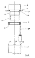
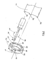
- an actuator 10 incorporating the present invention, comprises an enlarged sleeve 12, provided with a sealing gasket 14, assembled on a panel board 16 according to a preset angular direction determined by a tooth 18 within a corresponding seat made in the edge of a circular hole housing said actuator.
- the actuator 10 comprises connected to the enlarged sleeve 12 a first threaded tubular portion 20 continued in a second tubular not threaded more restricted portion usefull as a centering guide for a fastening ring nut 24 formed by a tubular member, preferably of plastics obtainable by moulding, internally threaded for engaging the first tubular threaded region 20, said nut being provided with slots or reentring seats, having a shape for housing the blade of a screwdriver 28, in the externally faced basis thereof.
- said ring nut 24 has also peripheral seats or recesses 30 housing teeth 32 of a traditional socket wrench 34 alredy used in the prior art depicted in the above mentioned European Patent.
- the operation of the invention is the following one: if it is desired to fasten the actuator 10 to the panel board 16, the nut 24 must be tightened against the internal surface of said panel board 16, beginning to hand screw said ring nut 24 on the threaded portion 20.
- a screwdriver 28 advancing it in the direction of the arrow 36 to insert its blade into one of the slots 26, and then said screwdriver 28 is rotated according to the arrow 38, so causing the tightening of said ring nut against the internal surface of the panel board 16 and, thus, the fastening of the actuator 10 to the panel board.
- the presence of the peripheral seats or recesses 30 allows also the traditional use of the socket wrench 34 provided with teeth 32, actually allowing to tighten the ring nut with a more uniform strain distibution of less strength thereon.
Landscapes
- Engineering & Computer Science (AREA)
- Power Engineering (AREA)
- Switches With Compound Operations (AREA)
- Push-Button Switches (AREA)
- Cookers (AREA)
- Lock And Its Accessories (AREA)
Priority Applications (1)
| Application Number | Priority Date | Filing Date | Title |
|---|---|---|---|
| AT9090202578T ATE104804T1 (de) | 1990-02-13 | 1990-09-28 | Sicherungsringmutter fuer druckknopfschalter und schaltbetaetiger oder dergleichen. |
Applications Claiming Priority (2)
| Application Number | Priority Date | Filing Date | Title |
|---|---|---|---|
| IT02061090U IT219234Z2 (it) | 1990-02-13 | 1990-02-13 | Ghiera di fissaggio di operatori di pulsanti, commutatori e simili. |
| IT2061090U | 1990-02-13 |
Publications (3)
| Publication Number | Publication Date |
|---|---|
| EP0442158A2 true EP0442158A2 (de) | 1991-08-21 |
| EP0442158A3 EP0442158A3 (en) | 1991-08-28 |
| EP0442158B1 EP0442158B1 (de) | 1994-04-20 |
Family
ID=11169517
Family Applications (1)
| Application Number | Title | Priority Date | Filing Date |
|---|---|---|---|
| EP90202578A Expired - Lifetime EP0442158B1 (de) | 1990-02-13 | 1990-09-28 | Sicherungsringmutter für Druckknopfschalter und Schaltbetätiger oder dergleichen |
Country Status (4)
| Country | Link |
|---|---|
| EP (1) | EP0442158B1 (de) |
| AT (1) | ATE104804T1 (de) |
| DE (1) | DE69008333T2 (de) |
| IT (1) | IT219234Z2 (de) |
Family Cites Families (3)
| Publication number | Priority date | Publication date | Assignee | Title |
|---|---|---|---|---|
| FR1478524A (fr) * | 1966-03-11 | 1967-04-28 | Prec Mecanique Labinal | Rondelle perfectionnée à cotes d'épaisseurs multiples notamment pour la fixation d'appareillage électrique |
| JPS58117023U (ja) * | 1982-02-03 | 1983-08-10 | 株式会社 サン電業社 | スイツチ等の取付装置 |
| IT8223069U1 (it) * | 1982-10-01 | 1984-04-01 | Cge Compagnia Generale Di Elett Spa | Dispositivo di fissaggio ad innesto con bloccaggio a scatto per unita' di comando e/o di segnalazione |
-
1990
- 1990-02-13 IT IT02061090U patent/IT219234Z2/it active IP Right Grant
- 1990-09-28 DE DE69008333T patent/DE69008333T2/de not_active Expired - Fee Related
- 1990-09-28 AT AT9090202578T patent/ATE104804T1/de not_active IP Right Cessation
- 1990-09-28 EP EP90202578A patent/EP0442158B1/de not_active Expired - Lifetime
Also Published As
| Publication number | Publication date |
|---|---|
| EP0442158B1 (de) | 1994-04-20 |
| IT9020610U1 (it) | 1991-08-13 |
| IT219234Z2 (it) | 1993-02-08 |
| DE69008333D1 (de) | 1994-05-26 |
| DE69008333T2 (de) | 1994-11-17 |
| ATE104804T1 (de) | 1994-05-15 |
| IT9020610V0 (it) | 1990-02-13 |
| EP0442158A3 (en) | 1991-08-28 |
Similar Documents
| Publication | Publication Date | Title |
|---|---|---|
| CA2220818C (en) | Lockable turnbuckle assembly | |
| US4863326A (en) | Captive fastener | |
| US4557654A (en) | Cover of a nut in engagement with a bolt | |
| US4267870A (en) | Screw fastener with multi-point wrenching head and locking capabilities | |
| US5238342A (en) | Blind fastener with mechanical thread lock | |
| US5590975A (en) | Fastening assembly | |
| US7959392B2 (en) | U-nut fastener assembly | |
| US4952107A (en) | Captive panel screw assembly | |
| US6183293B1 (en) | Electrical connector latching mechanism | |
| EP0115671A1 (de) | Schnell lösbares Verbindungselement | |
| US5967723A (en) | Nut and bolt locking system | |
| GB2186047A (en) | Plastics nut and fastener comprising a screw and said nut | |
| EP0065414B1 (de) | Gewindemutter mit Sicherung | |
| US4078471A (en) | Fastening device | |
| EP0442158B1 (de) | Sicherungsringmutter für Druckknopfschalter und Schaltbetätiger oder dergleichen | |
| JP2002357344A (ja) | ファン付ルーバの取付け構造 | |
| EP0470696B1 (de) | Vorrichtung zum Verbinden von zwei Elementen | |
| US4253486A (en) | Control device mounting means and parts therefor | |
| JPH11287232A (ja) | ナットの共回り防止構造 | |
| KR19980043346U (ko) | 풀림방지용 와셔부재 | |
| JP2002055312A (ja) | レンズ取付具及びレンズ取付部の構造 | |
| KR0149333B1 (ko) | 과조임 방지용 볼트 | |
| JPH06264478A (ja) | カランの取付構造 | |
| KR0131966Y1 (ko) | 어선, 차량 등의 표시판 봉인 체결구 | |
| KR0178920B1 (ko) | 스페셜 스크루용 공구 |
Legal Events
| Date | Code | Title | Description |
|---|---|---|---|
| PUAI | Public reference made under article 153(3) epc to a published international application that has entered the european phase |
Free format text: ORIGINAL CODE: 0009012 |
|
| PUAL | Search report despatched |
Free format text: ORIGINAL CODE: 0009013 |
|
| AK | Designated contracting states |
Kind code of ref document: A2 Designated state(s): AT BE CH DE DK ES FR GB GR IT LI LU NL SE |
|
| AK | Designated contracting states |
Kind code of ref document: A3 Designated state(s): AT BE CH DE DK ES FR GB GR IT LI LU NL SE |
|
| 17P | Request for examination filed |
Effective date: 19920109 |
|
| 17Q | First examination report despatched |
Effective date: 19930714 |
|
| GRAA | (expected) grant |
Free format text: ORIGINAL CODE: 0009210 |
|
| AK | Designated contracting states |
Kind code of ref document: B1 Designated state(s): AT BE CH DE DK ES FR GB GR IT LI LU NL SE |
|
| PG25 | Lapsed in a contracting state [announced via postgrant information from national office to epo] |
Ref country code: SE Free format text: THE PATENT HAS BEEN ANNULLED BY A DECISION OF A NATIONAL AUTHORITY Effective date: 19940420 Ref country code: NL Effective date: 19940420 Ref country code: LI Effective date: 19940420 Ref country code: GR Free format text: LAPSE BECAUSE OF FAILURE TO SUBMIT A TRANSLATION OF THE DESCRIPTION OR TO PAY THE FEE WITHIN THE PRESCRIBED TIME-LIMIT Effective date: 19940420 Ref country code: ES Free format text: THE PATENT HAS BEEN ANNULLED BY A DECISION OF A NATIONAL AUTHORITY Effective date: 19940420 Ref country code: DK Effective date: 19940420 Ref country code: CH Effective date: 19940420 Ref country code: BE Effective date: 19940420 Ref country code: AT Effective date: 19940420 |
|
| REF | Corresponds to: |
Ref document number: 104804 Country of ref document: AT Date of ref document: 19940515 Kind code of ref document: T |
|
| ITF | It: translation for a ep patent filed | ||
| REF | Corresponds to: |
Ref document number: 69008333 Country of ref document: DE Date of ref document: 19940526 |
|
| ET | Fr: translation filed | ||
| REG | Reference to a national code |
Ref country code: CH Ref legal event code: PL |
|
| NLV1 | Nl: lapsed or annulled due to failure to fulfill the requirements of art. 29p and 29m of the patents act | ||
| PG25 | Lapsed in a contracting state [announced via postgrant information from national office to epo] |
Ref country code: GB Effective date: 19940928 |
|
| PG25 | Lapsed in a contracting state [announced via postgrant information from national office to epo] |
Ref country code: LU Free format text: LAPSE BECAUSE OF NON-PAYMENT OF DUE FEES Effective date: 19940930 |
|
| PLBE | No opposition filed within time limit |
Free format text: ORIGINAL CODE: 0009261 |
|
| STAA | Information on the status of an ep patent application or granted ep patent |
Free format text: STATUS: NO OPPOSITION FILED WITHIN TIME LIMIT |
|
| 26N | No opposition filed | ||
| GBPC | Gb: european patent ceased through non-payment of renewal fee |
Effective date: 19940928 |
|
| PGFP | Annual fee paid to national office [announced via postgrant information from national office to epo] |
Ref country code: DE Payment date: 20031128 Year of fee payment: 14 |
|
| PGFP | Annual fee paid to national office [announced via postgrant information from national office to epo] |
Ref country code: FR Payment date: 20031230 Year of fee payment: 14 |
|
| PG25 | Lapsed in a contracting state [announced via postgrant information from national office to epo] |
Ref country code: DE Free format text: LAPSE BECAUSE OF NON-PAYMENT OF DUE FEES Effective date: 20050401 |
|
| PG25 | Lapsed in a contracting state [announced via postgrant information from national office to epo] |
Ref country code: FR Free format text: LAPSE BECAUSE OF NON-PAYMENT OF DUE FEES Effective date: 20050531 |
|
| REG | Reference to a national code |
Ref country code: FR Ref legal event code: ST |
|
| PG25 | Lapsed in a contracting state [announced via postgrant information from national office to epo] |
Ref country code: IT Free format text: LAPSE BECAUSE OF NON-PAYMENT OF DUE FEES;WARNING: LAPSES OF ITALIAN PATENTS WITH EFFECTIVE DATE BEFORE 2007 MAY HAVE OCCURRED AT ANY TIME BEFORE 2007. THE CORRECT EFFECTIVE DATE MAY BE DIFFERENT FROM THE ONE RECORDED. Effective date: 20050928 |