EP0442327A1 - Device to check the presence of threads on spinning machines - Google Patents
Device to check the presence of threads on spinning machines Download PDFInfo
- Publication number
- EP0442327A1 EP0442327A1 EP91101266A EP91101266A EP0442327A1 EP 0442327 A1 EP0442327 A1 EP 0442327A1 EP 91101266 A EP91101266 A EP 91101266A EP 91101266 A EP91101266 A EP 91101266A EP 0442327 A1 EP0442327 A1 EP 0442327A1
- Authority
- EP
- European Patent Office
- Prior art keywords
- thread
- sensor
- container
- traveller
- ring
- Prior art date
- Legal status (The legal status is an assumption and is not a legal conclusion. Google has not performed a legal analysis and makes no representation as to the accuracy of the status listed.)
- Granted
Links
- 238000009987 spinning Methods 0.000 title claims abstract description 11
- 230000035939 shock Effects 0.000 claims abstract description 4
- 239000011347 resin Substances 0.000 claims description 3
- 229920005989 resin Polymers 0.000 claims description 3
- 208000019300 CLIPPERS Diseases 0.000 description 3
- 208000021930 chronic lymphocytic inflammation with pontine perivascular enhancement responsive to steroids Diseases 0.000 description 3
- 239000011248 coating agent Substances 0.000 description 2
- 238000000576 coating method Methods 0.000 description 2
- 230000006835 compression Effects 0.000 description 2
- 238000007906 compression Methods 0.000 description 2
- 238000010586 diagram Methods 0.000 description 2
- 238000009434 installation Methods 0.000 description 2
- 230000001681 protective effect Effects 0.000 description 2
- 238000002166 wet spinning Methods 0.000 description 2
- 230000005355 Hall effect Effects 0.000 description 1
- 238000013016 damping Methods 0.000 description 1
- 230000001419 dependent effect Effects 0.000 description 1
- 230000000694 effects Effects 0.000 description 1
- XEEYBQQBJWHFJM-UHFFFAOYSA-N iron Substances [Fe] XEEYBQQBJWHFJM-UHFFFAOYSA-N 0.000 description 1
- 229910052742 iron Inorganic materials 0.000 description 1
- 239000000696 magnetic material Substances 0.000 description 1
- 238000012423 maintenance Methods 0.000 description 1
- 239000000463 material Substances 0.000 description 1
- 238000000034 method Methods 0.000 description 1
- 238000012986 modification Methods 0.000 description 1
- 230000004048 modification Effects 0.000 description 1
- 230000000737 periodic effect Effects 0.000 description 1
- 230000001105 regulatory effect Effects 0.000 description 1
- 238000007378 ring spinning Methods 0.000 description 1
- 239000000126 substance Substances 0.000 description 1
- 238000011144 upstream manufacturing Methods 0.000 description 1
- 239000002699 waste material Substances 0.000 description 1
- XLYOFNOQVPJJNP-UHFFFAOYSA-N water Substances O XLYOFNOQVPJJNP-UHFFFAOYSA-N 0.000 description 1
Images


Classifications
-
- D—TEXTILES; PAPER
- D01—NATURAL OR MAN-MADE THREADS OR FIBRES; SPINNING
- D01H—SPINNING OR TWISTING
- D01H13/00—Other common constructional features, details or accessories
- D01H13/14—Warning or safety devices, e.g. automatic fault detectors, stop motions ; Monitoring the entanglement of slivers in drafting arrangements
- D01H13/16—Warning or safety devices, e.g. automatic fault detectors, stop motions ; Monitoring the entanglement of slivers in drafting arrangements responsive to reduction in material tension, failure of supply, or breakage, of material
- D01H13/1616—Warning or safety devices, e.g. automatic fault detectors, stop motions ; Monitoring the entanglement of slivers in drafting arrangements responsive to reduction in material tension, failure of supply, or breakage, of material characterised by the detector
-
- B—PERFORMING OPERATIONS; TRANSPORTING
- B65—CONVEYING; PACKING; STORING; HANDLING THIN OR FILAMENTARY MATERIAL
- B65H—HANDLING THIN OR FILAMENTARY MATERIAL, e.g. SHEETS, WEBS, CABLES
- B65H63/00—Warning or safety devices, e.g. automatic fault detectors, stop-motions ; Quality control of the package
- B65H63/02—Warning or safety devices, e.g. automatic fault detectors, stop-motions ; Quality control of the package responsive to reduction in material tension, failure of supply, or breakage, of material
- B65H63/024—Warning or safety devices, e.g. automatic fault detectors, stop-motions ; Quality control of the package responsive to reduction in material tension, failure of supply, or breakage, of material responsive to breakage of materials
- B65H63/028—Warning or safety devices, e.g. automatic fault detectors, stop-motions ; Quality control of the package responsive to reduction in material tension, failure of supply, or breakage, of material responsive to breakage of materials characterised by the detecting or sensing element
- B65H63/032—Warning or safety devices, e.g. automatic fault detectors, stop-motions ; Quality control of the package responsive to reduction in material tension, failure of supply, or breakage, of material responsive to breakage of materials characterised by the detecting or sensing element electrical or pneumatic
- B65H63/0321—Warning or safety devices, e.g. automatic fault detectors, stop-motions ; Quality control of the package responsive to reduction in material tension, failure of supply, or breakage, of material responsive to breakage of materials characterised by the detecting or sensing element electrical or pneumatic using electronic actuators
- B65H63/0325—Warning or safety devices, e.g. automatic fault detectors, stop-motions ; Quality control of the package responsive to reduction in material tension, failure of supply, or breakage, of material responsive to breakage of materials characterised by the detecting or sensing element electrical or pneumatic using electronic actuators using fluid sensing means, e.g. acoustic
-
- B—PERFORMING OPERATIONS; TRANSPORTING
- B65—CONVEYING; PACKING; STORING; HANDLING THIN OR FILAMENTARY MATERIAL
- B65H—HANDLING THIN OR FILAMENTARY MATERIAL, e.g. SHEETS, WEBS, CABLES
- B65H2701/00—Handled material; Storage means
- B65H2701/30—Handled filamentary material
- B65H2701/31—Textiles threads or artificial strands of filaments
Definitions
- This invention concerns a device to check the presence of threads on spinning machines. To be more exact, the invention is applied properly to ring spinning machines.
- the invention can be fitted to any spinning machine and is especially advantageous in the case of wet spinning frames for linen or other analogous fibres or the like.
- a device to check the presence of the thread in a spinning machine is always associated with another device which is normally positioned upstream of the drafting zone and which serves to halt the thread, so that the thread is not wound on elements in motion and does not damage them or else so that there is no loss of thread being sent to waste.
- One type includes a sensor to detect the presnce of the thread and, if the thread is lacking, a circuit to actuate a thread-arresting device is actuated.
- a type of sensor may be mechanical with a lever or be piezoelectric, or may include a photosensitive element or may operate by Hall effect or with an encoder-type position transducer, etc.
- This metallic thread-guide traveller in passing in front of the sensor modifies periodically the magnetic field which affects the sensor. By measuring and processing these periodic modifications a signal indicating the presence or otherwise of the thread is obtained.
- This device which is very accurate and reliable in itself, is no longer so when the thread-guide traveller is made of plastic or, at any rate, of a material which has no effect on the sensible magnetic field that affects the sensor.
- FR-A-2.161.471 discloses a system to monitor the presence of the thread on the basis of the fact that the thread modifies an acoustic signal coming from an emitter of ultrasonic sounds.
- This system is different from our invention under examination owing to the fact that the acoustic source is produced not in a natural manner by the thread and/or the traveller rotating on the ring of the spinning machine but artificially by an emitter of ultrasonic sounds, and also because the system consists of two active components, namely an emitter and a receiver, and also owing to the fact that this system monitors directly the presence of the thread and works in the field of ultrasonic sounds. All these differences together make the teaching of FR-A-2.161.471 not capable of being applied to the problems which our invention purposes to overcome.
- the device to check the presence of thread on spinning machines according to the invention is set forth and characterised in the main claim, while the dependent claims describe variants of the idea of the original solution.
- a microphonic sensor is located in cooperation with a radial position of the circumferential path of the traveller.
- microphonic sensor any type of element sensitive to sound, such as a variable contact transducer, a moving-iron transducer, an electrostatic transducer, a piezoelectric transducer, a moving-coil transducer, etc., and equivalent circuit means.
- This microphonic sensor is anchored advantageously to the ring rail.
- the microphonic sensor is lodged in a waterproof protective container and is sunk in at least one damping substance.
- a unit to process at least partly the signal received from the microphonic sensor is also lodged within the protective container.
- the microphonic sensor detects the cycles of rarefied air and compressed air which accompany the passage of the thread-guide traveller. These cycles are sensed by the sensor as shock waves and therefore as a regular variation of the noise generated by the traveller; this noise laps the microphonic sensor.
- the microphonic sensor is lapped only by background noise.
- the container if included, will have an outer width and height ranging from 1.5 to 3 cms. and will have advantageously, but not only, a circular section.
- the microphonic sensor is lodged within the container and will take up advantageously at least a third of the length of the container.
- the length of the container is normally between 1.5 and 4 cms.
- the container may be positioned on the ring rail in a stationary position, or else the means which secure the container will be able to adjust the radial position of the container in relation to the guide ring of the thread-guide traveller.
- the distance of the container from the ring will be between 3 and 7 mm.
- the axis of the microphonic sensor, or of the container cooperates with the vicinity of the upper part of the ring.
- the microphonic sensor cooperates with electronic means that amplify, eliminate extraneous noise from and structure the signal, and with control and actuation means.
- the control and actuation means govern a device that cuts and arrests the thread.
- Operational-machine control and governing means are comprised.
- a spinning machine 11 comprises a movable spindle holder 12 that bears spindles 13 on which are fitted tubes 14 to accommodate the relative roving packages.
- the tube 14 is made vertically movable by the movable spindle holder 12 and cooperates with a stationary rail 15.
- a guide plate 19, drafting unit 20, thread arresting means 21 which also serves to cut the roving, a moistening vessel 22 in this case and a roving package 23 are positioned above the ring 16.
- a proximity sensor of a known type which detects the thread is normally fitted on the guide plate 19 but, as we said above, this invention has the purpose of substituting that sensor of a known type.
- both the sensor fitted on the guide plate 19 and a device 10 according to the invention positioned on the stationary ring rail 15 may be included.
- the device 10 is installed on the rail 15 by means of a strap 25, which clamps a container 24 whence electrical cables 26 emerge.
- the container 24 has its axis in a radial position in relation to the ring 16 and can be adjusted axially in relation to the ring 16 by means of the strap 25.
- the axis of the container 24 cooperates with the path of the passage of the traveller 18 so as to obtain the greatest impact from the shock wave.
- the axis of the container 24 lies substantially on a plane parallel to the plane of sliding of the traveller 18 but at an angle to the radial position of the ring 16.
- This angle may reach even a value of about fifteen degrees, depending on the type of microphonic sensor 27 employed, the characteristics of the container 24 and the speed of rotation of the traveller 18.
- the signal received by the device 10 (Fig.4a), if trasmitted to a signal system 33 by an amplifier 32, has a conformation whereby, unless there are disturbances, the peaks indicate the compression and rarefaction of the air.
- the signal received has the conformation shown by 35 in Fig.4b and represents the background noise.
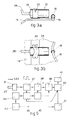
- Fig.5 shows a possible electrical block diagram associated with the device 10.
- This electrical block diagram includes a preamplifier-clipper 31, a filter amplifier 37, a counter 38, a memory 39, a clock assembly 40, a data assembly 41 and a power actuation assembly 42 which governs the arresting and cutting means 21.
- arresting and cutting means 21 is also governed by a minimum-speed permission assembly 43, which in turn gives permission to the feeder 44 of the electronic apparatus.
- the filter amplifier 37, clock assembly 40 and feeder 44 govern a control means 36, which actuates the power actuation assembly 42, if the device 10 has broken down, so as to perform cutting of the thread by means of the arresting and cutting means 21.
- Fig.6a shows a form of embodiment of the device 10 in which are illustrated the microphonic sensor 27 and preamplifier-clipper 31 before they undergo a resin-coating operation.
- Fig.6b shows the device 10 of Fig.6a after the resin-coating operation, whereby the microphonic sensor 27 is associated with the preamplifier-clipper 31 by application of a resin 30.
- Figs.6c and 6d are views of Fig.6b according to the lines of the arrows A and B respectively.
- Fig.6e shows a lengthwise section of the device 10 inserted together with resin 30 into a metallic or plastic container 24.
- the device 10 is anchored advantageously to the container 24 by a dope 45; the body of the container 24 is shut with a cover 28 and toroidal ring 29.
- the container 24 may have a width and height or diameter of 1.5 to 3 cms. and a length of 1.5 to 4 cms.
Landscapes
- Engineering & Computer Science (AREA)
- Mechanical Engineering (AREA)
- Textile Engineering (AREA)
- Quality & Reliability (AREA)
- Spinning Or Twisting Of Yarns (AREA)
- Spinning Methods And Devices For Manufacturing Artificial Fibers (AREA)
- Yarns And Mechanical Finishing Of Yarns Or Ropes (AREA)
- Eye Examination Apparatus (AREA)
- Electrical Discharge Machining, Electrochemical Machining, And Combined Machining (AREA)
- Investigating Materials By The Use Of Optical Means Adapted For Particular Applications (AREA)
Abstract
Description
- This invention concerns a device to check the presence of threads on spinning machines. To be more exact, the invention is applied properly to ring spinning machines.
- The invention can be fitted to any spinning machine and is especially advantageous in the case of wet spinning frames for linen or other analogous fibres or the like.
- It is known that on spinning machines it is necessary to provide a detector which senses whether or not the thread is passing through.
- In fact, if there is no thread, this means that the spool is not being fed and that the spindle is rotating to no purpose; in other words, time and energy are being wasted without achieving any result.
- A device to check the presence of the thread in a spinning machine is always associated with another device which is normally positioned upstream of the drafting zone and which serves to halt the thread, so that the thread is not wound on elements in motion and does not damage them or else so that there is no loss of thread being sent to waste.
- Devices to check the presence of the thread are known and are of various types. One type includes a sensor to detect the presnce of the thread and, if the thread is lacking, a circuit to actuate a thread-arresting device is actuated. Such a type of sensor may be mechanical with a lever or be piezoelectric, or may include a photosensitive element or may operate by Hall effect or with an encoder-type position transducer, etc.
- However, these types of sensor are not advantageous in given types of processing on spinning machines, nor are they advantageous with certain types of yarn.
- To obviate the drawbacks of these types of sensors, a sensor has been proposed in EP-A-0329618 and is fitted to the ring rail and detects the regular passage of the metallic thread-guide traveller.
- This metallic thread-guide traveller in passing in front of the sensor modifies periodically the magnetic field which affects the sensor. By measuring and processing these periodic modifications a signal indicating the presence or otherwise of the thread is obtained.
- This device, which is very accurate and reliable in itself, is no longer so when the thread-guide traveller is made of plastic or, at any rate, of a material which has no effect on the sensible magnetic field that affects the sensor.
- In this case, where the yarn to be processed requires a thread-guide traveller made of a non-magnetic material, it is necessary to forgo these sensors fitted to the ring rail and to employ sensors that act in direct cooperation with the thread.
- As we said earlier, these sensors are less accurate and reliable and also require continuous maintenance work to keep them at a reliable quality level. In fact, the presnce of dirt mixed with water lessens the reliability of these sensors considerably.
- Document WO-A-88/080 ⁴⁷ discloses a sensor which is intended to check the unit length weight or linear density of a sliver being processed. The signal arriving from the sensor positioned in a trumpet has the purpose of regulating the speed of the drawing rolls so as to obtain the greatest possible uniformity of the sliver. The sensor disclosed in this document monitors the acoustic emissions caused by natural compression of the fibres against each other and by their contact with the trumpet through which they are compelled to pass. Therefore, the field of employment of the sensor and its functional nature are clearly different from those for which the sensor of our invention is used.
- Document FR-A-2.161.471 discloses a system to monitor the presence of the thread on the basis of the fact that the thread modifies an acoustic signal coming from an emitter of ultrasonic sounds. This system is different from our invention under examination owing to the fact that the acoustic source is produced not in a natural manner by the thread and/or the traveller rotating on the ring of the spinning machine but artificially by an emitter of ultrasonic sounds, and also because the system consists of two active components, namely an emitter and a receiver, and also owing to the fact that this system monitors directly the presence of the thread and works in the field of ultrasonic sounds. All these differences together make the teaching of FR-A-2.161.471 not capable of being applied to the problems which our invention purposes to overcome.
- The present applicant has therefore tackled this problem in seeking a solution which meets requirements satifactorily.
- The device to check the presence of thread on spinning machines according to the invention is set forth and characterised in the main claim, while the dependent claims describe variants of the idea of the original solution.
- According to the invention a microphonic sensor is located in cooperation with a radial position of the circumferential path of the traveller.
- By microphonic sensor is meant any type of element sensitive to sound, such as a variable contact transducer, a moving-iron transducer, an electrostatic transducer, a piezoelectric transducer, a moving-coil transducer, etc., and equivalent circuit means. This microphonic sensor is anchored advantageously to the ring rail.
- According to a variant the microphonic sensor is lodged in a waterproof protective container and is sunk in at least one damping substance.
- According to a further variant a unit to process at least partly the signal received from the microphonic sensor is also lodged within the protective container.
- The microphonic sensor detects the cycles of rarefied air and compressed air which accompany the passage of the thread-guide traveller. These cycles are sensed by the sensor as shock waves and therefore as a regular variation of the noise generated by the traveller; this noise laps the microphonic sensor.
- When the traveller does not rotate since the thread is broken and does not set the traveller in rotation, the microphonic sensor is lapped only by background noise.
- According to the invention the container, if included, will have an outer width and height ranging from 1.5 to 3 cms. and will have advantageously, but not only, a circular section.
- The microphonic sensor is lodged within the container and will take up advantageously at least a third of the length of the container. The length of the container is normally between 1.5 and 4 cms.
- The container may be positioned on the ring rail in a stationary position, or else the means which secure the container will be able to adjust the radial position of the container in relation to the guide ring of the thread-guide traveller.
- Depending on the conformation of the container and the characteristics of the microphonic sensor, if the traveller rotates at 7000 revolutions a minute, the distance of the container from the ring will be between 3 and 7 mm.
- According to the invention the axis of the microphonic sensor, or of the container, cooperates with the vicinity of the upper part of the ring.
- The microphonic sensor cooperates with electronic means that amplify, eliminate extraneous noise from and structure the signal, and with control and actuation means. The control and actuation means govern a device that cuts and arrests the thread.
- Operational-machine control and governing means are comprised.
- The attached figures, which are given as a non-restrictive example, show the following:-
- Fig.1
- is a side view of a possible wet spinning frame for linen;
- Fig.2
- shows a possible installation of the invention;
- Figs.3
- show side and plan views of the installation of Fig.2;
- Figs.4
- show the working principle;
- Fig.5
- is a possible processing, control and actuation circuit;
- Figs.6
- show a possible embodiment of the invention in conjunction with a container.
- In the figures a
spinning machine 11 comprises amovable spindle holder 12 that bears spindles 13 on which are fittedtubes 14 to accommodate the relative roving packages. - The
tube 14 is made vertically movable by themovable spindle holder 12 and cooperates with astationary rail 15. - A
ring 16, on which arelative traveller 18 runs and is drawn bythread 17, is included on thestationary rail 15 for eachtube 14. - A
guide plate 19,drafting unit 20, thread arresting means 21 which also serves to cut the roving, amoistening vessel 22 in this case and aroving package 23 are positioned above thering 16. - A proximity sensor of a known type which detects the thread is normally fitted on the
guide plate 19 but, as we said above, this invention has the purpose of substituting that sensor of a known type. - According to a variant both the sensor fitted on the
guide plate 19 and adevice 10 according to the invention positioned on thestationary ring rail 15 may be included. - In the example shown the
device 10 is installed on therail 15 by means of astrap 25, which clamps acontainer 24 whenceelectrical cables 26 emerge. - The
container 24 has its axis in a radial position in relation to thering 16 and can be adjusted axially in relation to thering 16 by means of thestrap 25. - In this case the axis of the
container 24 cooperates with the path of the passage of thetraveller 18 so as to obtain the greatest impact from the shock wave. - According to a variant the axis of the
container 24 lies substantially on a plane parallel to the plane of sliding of thetraveller 18 but at an angle to the radial position of thering 16. - This angle may reach even a value of about fifteen degrees, depending on the type of
microphonic sensor 27 employed, the characteristics of thecontainer 24 and the speed of rotation of thetraveller 18. - When the
thread 17 passes thedevice 10, the signal received by the device 10 (Fig.4a), if trasmitted to asignal system 33 by anamplifier 32, has a conformation whereby, unless there are disturbances, the peaks indicate the compression and rarefaction of the air. - If the
thread 17 does not pass thedevice 10, the signal received has the conformation shown by 35 in Fig.4b and represents the background noise. - Fig.5 shows a possible electrical block diagram associated with the
device 10. - This electrical block diagram includes a preamplifier-
clipper 31, afilter amplifier 37, acounter 38, amemory 39, aclock assembly 40, adata assembly 41 and apower actuation assembly 42 which governs the arresting and cutting means 21. - In this example the arresting and cutting means 21 is also governed by a minimum-
speed permission assembly 43, which in turn gives permission to thefeeder 44 of the electronic apparatus. - The
filter amplifier 37,clock assembly 40 andfeeder 44 govern a control means 36, which actuates thepower actuation assembly 42, if thedevice 10 has broken down, so as to perform cutting of the thread by means of the arresting and cutting means 21. - Fig.6a shows a form of embodiment of the
device 10 in which are illustrated themicrophonic sensor 27 and preamplifier-clipper 31 before they undergo a resin-coating operation. - Fig.6b shows the
device 10 of Fig.6a after the resin-coating operation, whereby themicrophonic sensor 27 is associated with the preamplifier-clipper 31 by application of aresin 30.
Figs.6c and 6d are views of Fig.6b according to the lines of the arrows A and B respectively. - Fig.6e shows a lengthwise section of the
device 10 inserted together withresin 30 into a metallic orplastic container 24. - The
device 10 is anchored advantageously to thecontainer 24 by a dope 45; the body of thecontainer 24 is shut with acover 28 andtoroidal ring 29. - If the
container 24 is metallic, it may have a width and height or diameter of 1.5 to 3 cms. and a length of 1.5 to 4 cms.
Claims (6)
- Device to check the presence of threads on spinning machines (11), which is fitted to a stationary ring rail (15) and cooperates with a traveller (18) set in rotation on a ring (16) by the thread (17), the device (10) at least governing an arresting and cutting means (21) and being characterized in that it comprises a microphonic sensor (27) actuated by the shock waves due to the passage of the traveller (18).
- Device as claimed in Claim 1, in which the microphonic sensor (27) is suspended and contained in a container (24), which has its axis lying substantially on the plane of the sliding of the traveller (18) and is oriented towards the vertical axis of the ring (16) or the neighbourhood of the ring (16).
- Device as claimed in Claim 1 or 2, in which the microphonic sensor (27) is associated with means that select and control the signal received.
- Device as claimed in any claim hereinbefore, in which at least some of the means that select and control the signal received are contained in a circuit (31) placed within the container (24).
- Device as claimed in any claim hereinbefore, in which at least the microphonic sensor (27) and an electronic circuit (31) are associated by a resilient resin (30).
- Device as claimed in any claim hereinbefore, in which a fixture dope (45) is included in the container (24).
Applications Claiming Priority (2)
| Application Number | Priority Date | Filing Date | Title |
|---|---|---|---|
| IT83333A IT1238996B (en) | 1990-02-14 | 1990-02-14 | THREAD PRESENCE CONTROL DEVICE FOR THREADERS |
| IT8333390 | 1990-02-14 |
Publications (2)
| Publication Number | Publication Date |
|---|---|
| EP0442327A1 true EP0442327A1 (en) | 1991-08-21 |
| EP0442327B1 EP0442327B1 (en) | 1994-06-01 |
Family
ID=11320287
Family Applications (1)
| Application Number | Title | Priority Date | Filing Date |
|---|---|---|---|
| EP91101266A Expired - Lifetime EP0442327B1 (en) | 1990-02-14 | 1991-01-31 | Device to check the presence of threads on spinning machines |
Country Status (8)
| Country | Link |
|---|---|
| US (1) | US5140805A (en) |
| EP (1) | EP0442327B1 (en) |
| AT (1) | ATE106462T1 (en) |
| BR (1) | BR9100572A (en) |
| DE (1) | DE69102156T2 (en) |
| ES (1) | ES2054382T3 (en) |
| IE (1) | IE65591B1 (en) |
| IT (1) | IT1238996B (en) |
Cited By (3)
| Publication number | Priority date | Publication date | Assignee | Title |
|---|---|---|---|---|
| EP0699614A1 (en) * | 1994-08-30 | 1996-03-06 | AEROSPATIALE Société Nationale Industrielle | Method and device for monitoring the unwinding of a bobbin |
| DE19848050A1 (en) * | 1998-10-19 | 2000-04-20 | Rieter Ag Maschf | End break detector for spinning machine, comprises traveler cleaner |
| CN104294427A (en) * | 2013-07-17 | 2015-01-21 | 索若德国两合股份有限公司 | Ring spinning machine with sensor for detecting movement of traveller |
Families Citing this family (2)
| Publication number | Priority date | Publication date | Assignee | Title |
|---|---|---|---|---|
| CN107385581B (en) * | 2017-09-11 | 2022-10-04 | 上海兰宝传感科技股份有限公司 | Spinning frame steel wire ring rotation speed detection device |
| CH715390A1 (en) | 2018-09-27 | 2020-03-31 | Rieter Ag Maschf | Method for operating a ring spinning machine. |
Citations (3)
| Publication number | Priority date | Publication date | Assignee | Title |
|---|---|---|---|---|
| FR2161471A5 (en) * | 1971-11-24 | 1973-07-06 | Crouzet Sa | Static yarn detector - using ultrasonic transducers |
| WO1988008047A1 (en) * | 1987-04-10 | 1988-10-20 | Spinlab Partners, Ltd. | Apparatus and method for measuring a property of a continuous strand of fibrous materials |
| EP0329618A1 (en) * | 1988-02-16 | 1989-08-23 | INCAS S.p.A. | Magnetic sensor for detecting the breakage of the thread on ring spinning machines |
Family Cites Families (13)
| Publication number | Priority date | Publication date | Assignee | Title |
|---|---|---|---|---|
| NL102856C (en) * | 1958-08-08 | |||
| GB942791A (en) * | 1958-09-04 | 1963-11-27 | Electronics Bradford Ltd | Improvements in textile spinning and twisting machines |
| US3182489A (en) * | 1962-10-22 | 1965-05-11 | Delcon Corp | Ultrasonic contaminant detecting |
| US3745815A (en) * | 1970-10-17 | 1973-07-17 | Riv Officine Di Villar Perosa | Device for evaluating the vibrations of a revolving member |
| US3914754A (en) * | 1971-05-18 | 1975-10-21 | Martonair Ltd | Machine element position detection system |
| US3751893A (en) * | 1971-10-29 | 1973-08-14 | Leesona Corp | Strand detection |
| US3842663A (en) * | 1972-12-01 | 1974-10-22 | Boeing Co | Demodulated resonance analysis system |
| IT1006331B (en) * | 1974-02-11 | 1976-09-30 | Montefibre Spa | YARN BREAK DETECTOR DEVICE IN TOI IRONERS AND YARN |
| US3969882A (en) * | 1974-09-30 | 1976-07-20 | Manuel Cilloniz Oberti | Process and apparatus for fiber wetting in spinning device of the ring-spindle-traveler type |
| CH583656A5 (en) * | 1974-11-29 | 1977-01-14 | Loepfe Ag Geb | |
| DE3526309A1 (en) * | 1985-07-23 | 1987-01-29 | Schlafhorst & Co W | SPIDER |
| DE3526305A1 (en) * | 1985-07-23 | 1987-01-29 | Zinser Textilmaschinen Gmbh | SPIDER |
| DE3716829C2 (en) * | 1986-07-03 | 1994-12-15 | Zinser Textilmaschinen Gmbh | Method and device for reducing the failure rate of stop devices on a spinning machine |
-
1990
- 1990-02-14 IT IT83333A patent/IT1238996B/en active IP Right Grant
-
1991
- 1991-01-31 EP EP91101266A patent/EP0442327B1/en not_active Expired - Lifetime
- 1991-01-31 ES ES91101266T patent/ES2054382T3/en not_active Expired - Lifetime
- 1991-01-31 DE DE69102156T patent/DE69102156T2/en not_active Expired - Fee Related
- 1991-01-31 AT AT91101266T patent/ATE106462T1/en not_active IP Right Cessation
- 1991-02-04 IE IE37091A patent/IE65591B1/en not_active IP Right Cessation
- 1991-02-06 US US07/651,639 patent/US5140805A/en not_active Expired - Fee Related
- 1991-02-08 BR BR919100572A patent/BR9100572A/en unknown
Patent Citations (3)
| Publication number | Priority date | Publication date | Assignee | Title |
|---|---|---|---|---|
| FR2161471A5 (en) * | 1971-11-24 | 1973-07-06 | Crouzet Sa | Static yarn detector - using ultrasonic transducers |
| WO1988008047A1 (en) * | 1987-04-10 | 1988-10-20 | Spinlab Partners, Ltd. | Apparatus and method for measuring a property of a continuous strand of fibrous materials |
| EP0329618A1 (en) * | 1988-02-16 | 1989-08-23 | INCAS S.p.A. | Magnetic sensor for detecting the breakage of the thread on ring spinning machines |
Cited By (6)
| Publication number | Priority date | Publication date | Assignee | Title |
|---|---|---|---|---|
| EP0699614A1 (en) * | 1994-08-30 | 1996-03-06 | AEROSPATIALE Société Nationale Industrielle | Method and device for monitoring the unwinding of a bobbin |
| DE19848050A1 (en) * | 1998-10-19 | 2000-04-20 | Rieter Ag Maschf | End break detector for spinning machine, comprises traveler cleaner |
| CN104294427A (en) * | 2013-07-17 | 2015-01-21 | 索若德国两合股份有限公司 | Ring spinning machine with sensor for detecting movement of traveller |
| EP2826899A1 (en) * | 2013-07-17 | 2015-01-21 | Saurer Germany GmbH & Co. KG | Ring spinning machine with a sensor for detecting the movement of the traveller |
| DE102013011921A1 (en) * | 2013-07-17 | 2015-01-22 | Saurer Germany Gmbh & Co. Kg | Ring spinning machine with a sensor for detecting the movement of the ring traveler |
| CN104294427B (en) * | 2013-07-17 | 2017-09-01 | 索若德国两合股份有限公司 | The ring spinner of sensor with detection wire loop motion |
Also Published As
| Publication number | Publication date |
|---|---|
| IE65591B1 (en) | 1995-11-01 |
| EP0442327B1 (en) | 1994-06-01 |
| ES2054382T3 (en) | 1994-08-01 |
| US5140805A (en) | 1992-08-25 |
| DE69102156T2 (en) | 1994-09-08 |
| IT1238996B (en) | 1993-09-17 |
| ATE106462T1 (en) | 1994-06-15 |
| DE69102156D1 (en) | 1994-07-07 |
| IE910370A1 (en) | 1991-08-14 |
| BR9100572A (en) | 1991-10-29 |
| IT9083333A0 (en) | 1990-02-14 |
| IT9083333A1 (en) | 1991-08-15 |
Similar Documents
| Publication | Publication Date | Title |
|---|---|---|
| US4023341A (en) | Device for detecting the breakage of yarn in drawing frames and spinning frames | |
| US4450677A (en) | Thread monitor and a slubbing clamping device for draw frames of spinning machines equipped with double upper rollers | |
| EP0442327B1 (en) | Device to check the presence of threads on spinning machines | |
| US5083298A (en) | Monitoring apparatus | |
| GB1571667A (en) | Yarn supply device especially for knitting machines | |
| US3621267A (en) | Method and apparatus for detecting a break in longitudinally moving yarn | |
| US3854330A (en) | Apparatus for measuring mass density variations in a staple fiber sliver on spinning preparatory machines | |
| US4766647A (en) | Apparatus and method for measuring a property of a continuous strand of fibrous materials | |
| US3672143A (en) | Doffing apparatus and method | |
| US3751893A (en) | Strand detection | |
| US6543093B2 (en) | Apparatus for detecting displacements and/or presence of sliver in a fiber processing machine | |
| JPS63256731A (en) | Method and device for online management of production and quality in textile machinery | |
| US5621948A (en) | Method and apparatus for severing a sliver during coiler can replacement in a drawing frame | |
| NO770039L (en) | PROCEDURE AND DEVICE FOR AUTOMATIC TRUST DISPLAY IN SPINNING MACHINES. | |
| US3514615A (en) | Thread discontinuity and defect detection apparatus | |
| US3247662A (en) | Device for checking the run of the thread in a draw twisting frame or the like | |
| KR910001122A (en) | Wound counting device of the dread released from the weft feeder of the loom | |
| US4112665A (en) | Plural sensor ends down detecting apparatus | |
| US3272048A (en) | Apparatus for the detection of broken yarn and the like on textile machines | |
| US3938222A (en) | Tracking guide for planetary coiler | |
| JPS62282050A (en) | Yarn tension controller for knitting machine | |
| EP0616058A1 (en) | System to control the quality of yarn and relative device | |
| US3602727A (en) | Stop motion system for strand-handling machine | |
| GB2174415A (en) | Thread movement monitor for a knitting machine | |
| KR940002695B1 (en) | Yarn feeding device |
Legal Events
| Date | Code | Title | Description |
|---|---|---|---|
| PUAI | Public reference made under article 153(3) epc to a published international application that has entered the european phase |
Free format text: ORIGINAL CODE: 0009012 |
|
| AK | Designated contracting states |
Kind code of ref document: A1 Designated state(s): AT BE CH DE ES FR IT LI |
|
| 17P | Request for examination filed |
Effective date: 19920201 |
|
| 17Q | First examination report despatched |
Effective date: 19930802 |
|
| GRAA | (expected) grant |
Free format text: ORIGINAL CODE: 0009210 |
|
| ITF | It: translation for a ep patent filed | ||
| AK | Designated contracting states |
Kind code of ref document: B1 Designated state(s): AT BE CH DE ES FR IT LI |
|
| REF | Corresponds to: |
Ref document number: 106462 Country of ref document: AT Date of ref document: 19940615 Kind code of ref document: T |
|
| REF | Corresponds to: |
Ref document number: 69102156 Country of ref document: DE Date of ref document: 19940707 |
|
| ET | Fr: translation filed | ||
| REG | Reference to a national code |
Ref country code: ES Ref legal event code: FG2A Ref document number: 2054382 Country of ref document: ES Kind code of ref document: T3 |
|
| PLBE | No opposition filed within time limit |
Free format text: ORIGINAL CODE: 0009261 |
|
| STAA | Information on the status of an ep patent application or granted ep patent |
Free format text: STATUS: NO OPPOSITION FILED WITHIN TIME LIMIT |
|
| 26N | No opposition filed | ||
| PGFP | Annual fee paid to national office [announced via postgrant information from national office to epo] |
Ref country code: DE Payment date: 20010122 Year of fee payment: 11 |
|
| PGFP | Annual fee paid to national office [announced via postgrant information from national office to epo] |
Ref country code: FR Payment date: 20010123 Year of fee payment: 11 |
|
| PGFP | Annual fee paid to national office [announced via postgrant information from national office to epo] |
Ref country code: AT Payment date: 20010125 Year of fee payment: 11 |
|
| PGFP | Annual fee paid to national office [announced via postgrant information from national office to epo] |
Ref country code: CH Payment date: 20010219 Year of fee payment: 11 |
|
| PGFP | Annual fee paid to national office [announced via postgrant information from national office to epo] |
Ref country code: ES Payment date: 20010228 Year of fee payment: 11 |
|
| PGFP | Annual fee paid to national office [announced via postgrant information from national office to epo] |
Ref country code: BE Payment date: 20010313 Year of fee payment: 11 |
|
| PG25 | Lapsed in a contracting state [announced via postgrant information from national office to epo] |
Ref country code: LI Free format text: LAPSE BECAUSE OF NON-PAYMENT OF DUE FEES Effective date: 20020131 Ref country code: CH Free format text: LAPSE BECAUSE OF NON-PAYMENT OF DUE FEES Effective date: 20020131 Ref country code: BE Free format text: LAPSE BECAUSE OF NON-PAYMENT OF DUE FEES Effective date: 20020131 Ref country code: AT Free format text: LAPSE BECAUSE OF NON-PAYMENT OF DUE FEES Effective date: 20020131 |
|
| PG25 | Lapsed in a contracting state [announced via postgrant information from national office to epo] |
Ref country code: ES Free format text: LAPSE BECAUSE OF NON-PAYMENT OF DUE FEES Effective date: 20020201 |
|
| BERE | Be: lapsed |
Owner name: ZIGNAGO TESSILE S.P.A. Effective date: 20020131 |
|
| PG25 | Lapsed in a contracting state [announced via postgrant information from national office to epo] |
Ref country code: DE Free format text: LAPSE BECAUSE OF NON-PAYMENT OF DUE FEES Effective date: 20020801 |
|
| REG | Reference to a national code |
Ref country code: CH Ref legal event code: PL |
|
| PG25 | Lapsed in a contracting state [announced via postgrant information from national office to epo] |
Ref country code: FR Free format text: LAPSE BECAUSE OF NON-PAYMENT OF DUE FEES Effective date: 20020930 |
|
| REG | Reference to a national code |
Ref country code: FR Ref legal event code: ST |
|
| REG | Reference to a national code |
Ref country code: ES Ref legal event code: FD2A Effective date: 20031122 |
|
| PG25 | Lapsed in a contracting state [announced via postgrant information from national office to epo] |
Ref country code: IT Free format text: LAPSE BECAUSE OF NON-PAYMENT OF DUE FEES;WARNING: LAPSES OF ITALIAN PATENTS WITH EFFECTIVE DATE BEFORE 2007 MAY HAVE OCCURRED AT ANY TIME BEFORE 2007. THE CORRECT EFFECTIVE DATE MAY BE DIFFERENT FROM THE ONE RECORDED. Effective date: 20050131 |