EP0442364A2 - Injection moulding machine for working with plastics - Google Patents
Injection moulding machine for working with plastics Download PDFInfo
- Publication number
- EP0442364A2 EP0442364A2 EP91101603A EP91101603A EP0442364A2 EP 0442364 A2 EP0442364 A2 EP 0442364A2 EP 91101603 A EP91101603 A EP 91101603A EP 91101603 A EP91101603 A EP 91101603A EP 0442364 A2 EP0442364 A2 EP 0442364A2
- Authority
- EP
- European Patent Office
- Prior art keywords
- pivot point
- rapid traverse
- piston rod
- movable platen
- tool
- Prior art date
- Legal status (The legal status is an assumption and is not a legal conclusion. Google has not performed a legal analysis and makes no representation as to the accuracy of the status listed.)
- Withdrawn
Links
Images


Classifications
-
- B—PERFORMING OPERATIONS; TRANSPORTING
- B29—WORKING OF PLASTICS; WORKING OF SUBSTANCES IN A PLASTIC STATE IN GENERAL
- B29C—SHAPING OR JOINING OF PLASTICS; SHAPING OF MATERIAL IN A PLASTIC STATE, NOT OTHERWISE PROVIDED FOR; AFTER-TREATMENT OF THE SHAPED PRODUCTS, e.g. REPAIRING
- B29C45/00—Injection moulding, i.e. forcing the required volume of moulding material through a nozzle into a closed mould; Apparatus therefor
- B29C45/17—Component parts, details or accessories; Auxiliary operations
- B29C45/1751—Adjustment means allowing the use of moulds of different thicknesses
-
- B—PERFORMING OPERATIONS; TRANSPORTING
- B29—WORKING OF PLASTICS; WORKING OF SUBSTANCES IN A PLASTIC STATE IN GENERAL
- B29C—SHAPING OR JOINING OF PLASTICS; SHAPING OF MATERIAL IN A PLASTIC STATE, NOT OTHERWISE PROVIDED FOR; AFTER-TREATMENT OF THE SHAPED PRODUCTS, e.g. REPAIRING
- B29C45/00—Injection moulding, i.e. forcing the required volume of moulding material through a nozzle into a closed mould; Apparatus therefor
- B29C45/17—Component parts, details or accessories; Auxiliary operations
- B29C45/64—Mould opening, closing or clamping devices
- B29C45/67—Mould opening, closing or clamping devices hydraulic
- B29C45/6707—Mould opening, closing or clamping devices hydraulic without relative movement between the piston and the cylinder of the clamping device during the mould opening or closing movement
- B29C45/6714—Mould opening, closing or clamping devices hydraulic without relative movement between the piston and the cylinder of the clamping device during the mould opening or closing movement using a separate element transmitting the mould clamping force from the clamping cylinder to the mould
- B29C45/6728—Mould opening, closing or clamping devices hydraulic without relative movement between the piston and the cylinder of the clamping device during the mould opening or closing movement using a separate element transmitting the mould clamping force from the clamping cylinder to the mould the separate element consisting of coupling rods
-
- B—PERFORMING OPERATIONS; TRANSPORTING
- B29—WORKING OF PLASTICS; WORKING OF SUBSTANCES IN A PLASTIC STATE IN GENERAL
- B29C—SHAPING OR JOINING OF PLASTICS; SHAPING OF MATERIAL IN A PLASTIC STATE, NOT OTHERWISE PROVIDED FOR; AFTER-TREATMENT OF THE SHAPED PRODUCTS, e.g. REPAIRING
- B29C45/00—Injection moulding, i.e. forcing the required volume of moulding material through a nozzle into a closed mould; Apparatus therefor
- B29C45/17—Component parts, details or accessories; Auxiliary operations
- B29C45/1761—Means for guiding movable mould supports or injection units on the machine base or frame; Machine bases or frames
Definitions
- the invention relates to an injection molding machine for plastics processing, consisting of an injection unit, a fixed and a platen that moves on a guide track of a base frame on slide shoes, the displacement movement of which is effected by long-stroke hydraulic rapid-motion cylinders.
- the two tool clamping plates can be locked to one another by means of columns supported in a tool clamping plate in a self-supporting manner when the mold is closed, with short-stroke hydraulic locking cylinders being used to generate the closing force.
- a tool height adjustment device is available, which is connected to the columns.
- Locking units are also known, on which the rapid traverse cylinder or cylinders are arranged behind the movable platen approximately at the center of gravity or symmetrically to the latter (plastics booklet 6 from 1977 p. 329 and DE AS 1136.799). With such a solution, the disadvantages described above are avoided, but this arrangement requires additional support devices for the rapid traverse cylinder or cylinders, and a larger footprint is required for the locking unit of the injection molding machine.
- the aim of the invention is to reduce the technical-economic effort for the displacement movement of the movable platen, the reduction of wear and the guarantee of a high level of functional reliability.
- the object of the invention is to develop a cost-effective rapid traverse drive for the movable platen in injection molding machines, which does not hinder access to the mold space, which ensures favorable power transmission to the movable platen and does not increase the overall length for the locking unit.
- the object is achieved in that at least one rapid traverse cylinder is arranged between the movable platen and the injection unit in such a way that its longitudinal axis is inclined at an acute angle with respect to the horizontal guide track.
- the rapid traverse cylinder is pivoted about a pivot point in the base frame of the injection molding machine.
- the end of the piston rod is pivotally connected to the sliding blocks of the movable platen at a pivot point.
- the vertical distance from the center of gravity of the movable platen with half of the mold to the pivot point in the slide shoe is smaller than the pivot point of the rapid traverse cylinder.
- the acute angle is a maximum of 30 ° in the retracted state of the piston rod and a minimum of 2 ° in the extended state.
- the injection molding machine 1 shown in simplified form in FIGS. 1 to 4 consists of a base frame 4, on which a fixed mold mounting plate 2 and a mold mounting plate 3, which is movable by rapid-motion cylinders 6 on slide shoes 5, with a mold 8 located therebetween, are arranged.
- the injection unit 12 is arranged to the right of the fixed platen 2, while in Figure 4 the injection unit 12 is to the left of the movable platen 3.
- the two tool clamping plates 2 and 3 are locked together in the moved-together state with the two halves of the molding tool 8, via the columns 7, which are supported in a self-supporting manner in one of the tool clamping plates.
- the closing force is applied via the closing cylinder 9, as a result of which blowing occurs during the injection process of the two halves of the mold is prevented.
- a tool height adjustment device for setting the tool installation height H, which is actuated via a chain drive 10.
- the rapid traverse cylinder 6 is pivotally mounted about a horizontal pivot point 13 in the base frame 4 of the injection molding machine 1. In its longitudinal axis 14, the rapid traverse cylinder 6 is inclined with respect to the horizontal guide path 15 of the base frame 4 by an angle ⁇ , which changes during the rapid traverse movement when the mold 8 is being opened and closed.
- the pivot point 13 for the rapid traverse cylinder 6 must be arranged between the movable platen 3 and the injection unit 12 within the base frame 4.
- the end of the piston rod 11, on the other hand, is articulated at the pivot point 16 to the sliding shoes 5 of the movable platen 3.
- the vertical distance a from the center of gravity S of the movable platen 3 with the mold half 8, the pillars 7 and the sliding shoes 5 to the pivot point 16 in the sliding block 5 must be smaller than the distance b to the pivot point 13 of the rapid traverse cylinder 6.
- the position of the rapid traverse cylinder 6 shown in FIG. 1 applies both to the closing movement in the braking phase and to the ascending movement in the acceleration phase of the movable platen 3.
- the position of the fixed fulcrum 16 for the piston rod 11 in the slide shoe depends on the arrangement of the injection unit. Is the injection unit 12 behind the fixed platen 2, the pivot point 13 for the storage of the rapid traverse cylinder 6 is arranged in the area of the base frame 4 below the fixed platen 2 (Fig. 1, 2 and 3). If, on the other hand, the injection unit 12 is arranged behind the movable platen 3 (FIG. 4), the pivot point 13 is located in the region of the base frame 4 below the injection unit 12. In this case too, the vertical distance a from the center of mass S of the movable platen 3 to the pivot point 16 in the sliding block 5 is smaller than the vertical distance b to the pivot point 13 of the rapid traverse cylinder 6.
- the fulcrum 16 is mounted between the piston rod 11 and the slide shoe 5 by means of a guide rod 17 arranged displaceably in the slide shoe 5. Furthermore, the chain drive 10 for the tool height adjustment device is coupled to the drive 18 for the guide rod 17.
- This arrangement has the advantage that by shifting the center of gravity S (for example, a larger tool height H means longer protruding columns 7), the force application point in the pivot point 16 also shifts. This has the result that a larger counter moment is generated by the increasing tilting moment of the movable platen 3 with mold half 8, by the simultaneous extension of the lever arms a and b for the introduction of force for the rapid movement.
Landscapes
- Engineering & Computer Science (AREA)
- Manufacturing & Machinery (AREA)
- Mechanical Engineering (AREA)
- Moulds For Moulding Plastics Or The Like (AREA)
- Injection Moulding Of Plastics Or The Like (AREA)
Abstract
Die Erfindung betrifft eine Spritzgieszmaschine bestehend aus einer Spritzeinheit (12), einer festen und einer auf einer Fuehrungsbahn (15) eines Grundrahmens (4) auf Gleitschuhen (5) durch langhubige hydraulische Eilgangzylinder (6) beweglichen Werkzeugaufspannplatte (3). Die Werkzeugaufspannplatten sind ueber darin freitragend gelagerte Saeulen (7) bei geschlossenem Formwerkzeug verriegelbar. Die Werkzeughoehe ist durch eine Werkzeughoehenverstellvorrichtung einstellbar. Ziel ist es, einen kostenguenstigen Eilgangantrieb zu entwickeln, der platzsparend angeordnet ist und den auftretenden Verschleisz reduziert. Die Loesung sieht vor die/den Eilgangzylinder (6) zwischen der beweglichen Werkzeugaufspannplatte (3) und der Spritzeinheit (12) so anzuordnen, dasz die Laengsachse (14) um einen spitzen Winkel (α) gegenueber der horizontalen Fuehrungsbahn (15) geneigt ist und am ausfahrseitigen Ende fuer die Kolbenstange um einen Drehpunkt (13) schwenkbar im Grundrahmen (4) gelagert ist. Das Ende der Kolbenstange ist in einem Drehpunkt (16) gelenkig mit den Gleitschuhen (5) verbunden, wobei der senkrechte Abstand (a) vom Massenschwerpunkt (S) der beweglichen Aufspannplatte (3) zum Drehpunkt (16) im Gleitschuh (5) kleiner ist als der senkrechte Abstand (b) zum Drehpunkt (13) des Eilgangzylinders (6).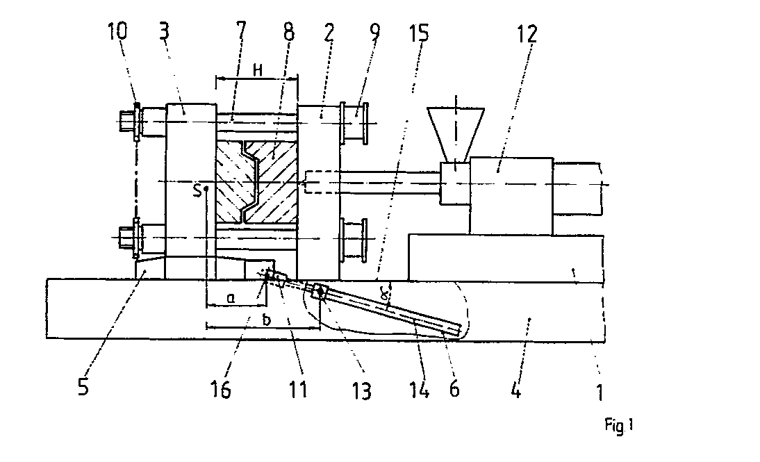
Description
Die Erfindung betrifft eine Spritzgieszmaschine zur Kunststoffverarbeitung, bestehend aus einer Spritzeinheit, einer festen und einer auf einer Fuehrungsbahn eines Grundrahmens auf Gleitschuhen beweglichen Werkzeugaufspannplatte, deren Verschiebebewegung durch langhubige hydraulische Eilgangzylinder erfolgt. Die beiden Werkzeugaufspannplatten sind durch in einer Werkzeugaufspannplatte freitragend gelagerte Saeulen bei geschlossenem Formwerkzeug miteinander verriegelbar, wobei zur Schlieszkrafterzeugung kurzhubige hydraulische Schlieszzylinder dienen. Zur Einstellung der Werkzeugeinbauhoehe ist eine Werkzeughoehenverstellvorrichtung vorhanden, die mit den Saeulen verbunden ist.The invention relates to an injection molding machine for plastics processing, consisting of an injection unit, a fixed and a platen that moves on a guide track of a base frame on slide shoes, the displacement movement of which is effected by long-stroke hydraulic rapid-motion cylinders. The two tool clamping plates can be locked to one another by means of columns supported in a tool clamping plate in a self-supporting manner when the mold is closed, with short-stroke hydraulic locking cylinders being used to generate the closing force. To adjust the tool installation height, a tool height adjustment device is available, which is connected to the columns.
Gattungsgemaesze Schlieszeinheiten mit freitragend in einer Werkzeugaufspannplatte gelagerten Saeulen sind auf dem DD WP 122.667, dem DD WP 146.406 und der US PS 3465.387 bekannt. Unterhalb der Werkzeugaufspannplatte und parallel zur Bewegungsrichtung der beweglichen Werkzeugaufspannplatte sind die Eilgangzylinder angeordnet, wobei sie sich in der DD PS 122.667 und der US PS zwischen dem Untersatz und der beweglichen Platte oder wie im DD WP 145.406 zwischen den beiden Werkzeugaufspannplatten befinden. Beide Loesungen haben den Vorteil, dasz die Zugaenglichkeit zum Werkzeugraum nicht eingeschraenkt wird, wodurch die Vorteile der freitragenden Saeulen hinsichtlich des Werkzeugwechsels und der Entnahme der Spritzguszteile wirksam werden.Generic locking units with cantilevered pillars in a platen are known on the DD WP 122.667, the DD WP 146.406 and the US PS 3465.387. The rapid traverse cylinders are arranged below the platen and parallel to the direction of movement of the movable platen, being located in the DD PS 122.667 and the US PS between the base and the movable platen or, as in DD WP 145.406, between the two platen. Both solutions have the advantage that the accessibility to the tool space is not restricted, as a result of which the advantages of the self-supporting columns with regard to the tool change and the removal of the injection molded parts become effective.
Von Nachteil bei diesen Loesungen ist jedoch, dasz der unterhalb des Massenschwerpunktes der beweglichen Werkzeugaufspannplatte liegende Kraftangriffspunkt beim Beschleunigen und Bremsen ein Kippmoment hervorruft, das zu einer Neigung der beweglichen Aufspannplatte fuehrt. Um diese Neigung moeglichst gering zu halten sind extrem steife und masseintensive Fuehrungselemente zwischen der beweglichen Werkzeugaufspannplatte und dem Maschinenbett erforderlich. Von Nachteil ist ferner der erhoehte Verschleisz der Gleit- und Rollelemente unter der beweglichen Werkzeugaufspannplatte, die durch die zu verhindernde Kippbewegung extrem belastet werden.A disadvantage of these solutions, however, is that the force application point when accelerating lies below the center of mass of the movable platen and braking causes a tilting moment which leads to an inclination of the movable platen. In order to keep this inclination as low as possible, extremely stiff and mass-intensive guide elements between the movable platen and the machine bed are required. Another disadvantage is the increased wear of the sliding and rolling elements under the movable platen, which are extremely stressed by the tilting movement to be prevented.
Bekannt sind auch Schlieszeinheiten, an denen der oder die Eilgangszylinder hinter der beweglichen Werkzeugaufspannplatte etwa im Massenschwerpunkt bzw. symmetrisch zu diesem, angeordnet sind (Kunststoffe Heft 6 von 1977 S. 329 und DE AS 1136.799). Mit einer derartigen Loesung werden zwar die zuvor beschriebenen Nachteile vermieden, jedoch sind durch diese Anordnung zusaetzliche Abstuetzvorrichtungen fuer den oder die Eilgangzylinder erforderlich, und es wird eine groeszere Aufstellflaeche fuer die Schlieszeinheit der Spritzgieszmaschine benoetigt.Locking units are also known, on which the rapid traverse cylinder or cylinders are arranged behind the movable platen approximately at the center of gravity or symmetrically to the latter (
In einer aelteren Anmeldung (WP B29C/322.120.6) wurde ein Eilgangantrieb vorgeschlagen, mit dem die bislang bekannten Nachteile beseitigt werden sollen. Die Loesung sieht vor, dasz ein kurzhubiger Eilgangzylinder, der um einen festen Drehpunkt am Grundrahmen schwenkbar gelagert ist ueber seine Kolbenstange mit einer Koppel verbunden ist. Die Koppel ist wiederum ueber ein Drehgelenk mit dem Endrahmen verbunden. Der Vorteil dieser Loesung besteht darin, dasz die Kraefte fuer den Eilgangantrieb in der Naehe der horizontalen Schwerachse der beweglichen Werkzeugaufspannplatte eingeleitet werden, ohne dasz sich die Baulaenge der Schlieszeinheit vergroeszert. Der Nachteil dieser Loesung besteht jedoch in dem relativ hohen technisch-oekonomisichen Aufwand fuer diesen Eilgangantrieb.In an older application (WP B29C / 322.120.6) a rapid traverse drive was proposed, with which the disadvantages known so far are to be eliminated. The solution provides that a short-stroke rapid-motion cylinder, which is pivotally mounted about a fixed pivot point on the base frame, is connected to a coupling via its piston rod. The coupling is in turn connected to the end frame via a swivel joint. The advantage of this solution is that the forces for the rapid traverse drive are introduced in the vicinity of the horizontal axis of gravity of the movable platen, without the construction length of the locking unit being increased. The disadvantage of this solution, however, is the relatively high technical-economic effort for this rapid traverse drive.
Ziel der Erfindung ist die Senkung des technisch-oekonomischen Aufwandes fuer die Verschiebebewegung der beweglichen Werkzeugaufspannplatte, die Reduzierung des auftretenden Verschleiszes und die Gewaehrleistung einer hohen Funktionssicherheit.The aim of the invention is to reduce the technical-economic effort for the displacement movement of the movable platen, the reduction of wear and the guarantee of a high level of functional reliability.
Aufgabe der Erfindung ist es, einen kostenguenstigen Eilgangantrieb fuer die bewegliche Werkzeugaufspannplatte bei Spritzgieszmaschinen zu entwickeln, der die Zugaenglichkeit zum Werkzeugraum nicht behindert, der eine guenstige Kraftuebertragung auf die bewegliche Werkzeugaufspannplatte gewaehrleistet und die Baulaenge fuer die Schlieszeinheit nicht vergroeszert.The object of the invention is to develop a cost-effective rapid traverse drive for the movable platen in injection molding machines, which does not hinder access to the mold space, which ensures favorable power transmission to the movable platen and does not increase the overall length for the locking unit.
Erfindungsgemaesz wird die Aufgabe dadurch geloest, dasz zwischen der beweglichen Werkzeugaufspannplatte und der Spritzeinheit mindestens ein Eilgangzylinder so angeordnet ist, dasz dessen Laengsachse um einen spitzen Winkel gegenueber der horizontalen Fuehrungsbahn geneigt ist. Am ausfahrseitigen Ende fuer die Kolbenstange ist der Eilgangzylinder um einen Drehpunkt schwenkbar im Grundrahmen der Spritzgieszmaschine gelagert. Das Ende der Kolbenstange ist in einem Drehpunkt gelenkig mit den Gleitschuhen der beweglichen Werkzeugaufspannplatte verbunden. Dabei ist der senkrechte Abstand vom Massenschwerpunkt der beweglichen Werkzeugaufspannplatte mit Formwerkzeughaelfte zum Drehpunkt im Gleitschuh kleiner als zum Drehpunkt des Eilgangzylinders.According to the invention, the object is achieved in that at least one rapid traverse cylinder is arranged between the movable platen and the injection unit in such a way that its longitudinal axis is inclined at an acute angle with respect to the horizontal guide track. At the exit end for the piston rod, the rapid traverse cylinder is pivoted about a pivot point in the base frame of the injection molding machine. The end of the piston rod is pivotally connected to the sliding blocks of the movable platen at a pivot point. The vertical distance from the center of gravity of the movable platen with half of the mold to the pivot point in the slide shoe is smaller than the pivot point of the rapid traverse cylinder.
In der weiteren Ausgestaltung der Erfindung ist es vorteilhaft, wenn der spitze Winkel im eingefahrenen Zustand der Kolbenstange maximal 30° und im ausgefahrenen Zustand minimal 2° betraegt.In a further embodiment of the invention, it is advantageous if the acute angle is a maximum of 30 ° in the retracted state of the piston rod and a minimum of 2 ° in the extended state.
Ferner ist es guenstig, das Ende der Kolbenstange im Drehpunkt gelenkig mit in den Gleitschuhen der beweglichen Werkzeugaufspannplatte verschiebbaren Fuehrungsstangen zu verbinden und den Kettenantrieb fuer die Werkzeughoehenverstellvorrichtung mit dem Antrieb zum Verschieben der Fuehrungsstange zu koppeln. Die Vorteile dieser Loesung bestehen darin, dasz der technisch-oekonomische Aufwand fuer den Eilgangantrieb gering ist. Durch die schraege und schwenkbare Anordnung des bzw. der Eilgangzylinder im Grundrahmen der Spritzgieszmaschine ist einerseits die uneingeschraenkte Zugaenglichkeit zum Werkzeugraum gewaehrleistet. Andererseits wird durch die schraege Krafteinleitung in die bewegliche Werkzeugaufspannplatte eine Kraftkomponente erzeugt, die dem auftretenden Kippmoment beim Beschleunigen und Abbremsen der beweglichen Werkzeugaufspannplatte entgegen wirkt, was zu einer Senkung des Verschleiszes und zu einer groeszeren Funktionssicherheit fuehrt.Furthermore, it is advantageous to connect the end of the piston rod in the pivot point to guide rods which can be displaced in the sliding blocks of the movable platen and to couple the chain drive for the tool height adjustment device to the drive for displacing the guide rod. The advantages of this solution are that the technical-economical effort for the rapid traverse drive is low. The inclined and swiveling arrangement of the rapid traverse cylinder (s) in the base frame of the injection molding machine ensures unrestricted access to the tool room. On the other hand, a force component is generated by the oblique introduction of force into the movable platen, which the counteracts the occurring tipping moment when accelerating and braking the movable platen, which leads to a reduction in wear and greater functional reliability.
Nachstehend wird die Erfindung in einem Ausfuehrungsbeispiel naeher erlaeutert. In den zugehoerigen Figuren ist dargestellt:
- Fig. 1:
- Spritzgieszmaschine mit eingefahrener Kolbenstange des Eilgangzylinders und hinter derfesten Werkzeugaufspannplatte angeordneter Spritzeinheit.
- Fig. 2:
- Spritzgieszmaschine gemaesz Fig. 1 mit ausgefahrener Kolbenstange des Eilgangzylinders.
- Fig. 3:
- Spritzgieszmaschine gemaesz Fig. 2, bei der der Kettentrieb fuer die Werkzeughoehenverstellvorrichtung mit dem Eilgangantrieb gekoppelt ist.
- Fig. 4:
- Spritzgieszmaschine mit eingefahrenem Eilgangzylinder und hinter der beweglichen Werkzeugaufspannplatte angeordneter Spritzeinheit.
- Fig. 1:
- Injection molding machine with retracted piston rod of the rapid traverse cylinder and injection unit arranged behind the fixed platen.
- Fig. 2:
- Injection molding machine according to Fig. 1 with the piston rod of the rapid traverse cylinder extended.
- Fig. 3:
- Injection molding machine according to FIG. 2, in which the chain drive for the tool height adjustment device is coupled to the rapid traverse drive.
- Fig. 4:
- Injection molding machine with retracted rapid traverse cylinder and injection unit arranged behind the movable platen.
Die in den Figuren 1 bis 4 vereinfacht dargestellte Spritzgieszmaschine 1 besteht aus einem Grundrahmen 4, auf dem eine feste Werkzeugaufspannplatte 2 und eine durch Eilgangzylinder 6 auf Gleitschuhen 5 bewegliche Werkzeugaufspannplatte 3, mit dazwischen befindlichen Formwerkzeug 8, angeordnet sind. In den Figuren 1, 2 und 3 ist rechts neben der festen Werkzeugaufspannplatte 2 die Spritzeinheit 12 angeordnet, waehrend sich in Figur 4 die Spritzeinheit 12 links neben der beweglichen Werkzeugaufspannplatte 3 befindet. In Abhaengigkeit vom Standort der Spritzeinheit 12, ergeben sich daraus fuer die Anordnung der Eilgangzylinder 6 unterschiedliche Ausfuehrungsformen, die aus den Figuren 1 und 4 ersichtlich sind. Die beiden Werkzeugaufspannplatten 2 und 3 werden im zusammengefahrenen Zustand mit den beiden Haelften des Formwerkzeuges 8, ueber die in einer der Werkzeugaufspannplatten freitragend gelagerten Saeulen 7 miteinander verriegelt. Ueber die Schlieszzylinder 9 wird die Schlieszkraft aufgebracht, wodurch waehrend des Einspritzvorganges ein Auftreiben der beiden Haelften des Formwerkzeuges verhindert wird. Am anderen Ende der Saeulen 7 befindet sich zur Einstellung dar Werkzeugeinbauhoehe H eine Werkzeughoehenverstellvorrichtung, die ueber einen Kettentrieb 10 betaetigt wird. In allen dargestellten Figuren ist der Eilgangzylinder 6 um einen horizontalen Drehpunkt 13 im Grundrahmen 4 der Spritzgieszmaschine 1 schwenkbar gelagert. In seiner Laengsachse 14 ist der Eilgangzylinder 6 gegenueber der horizontalen Fuehrungsbahn 15 des Grundrahmens 4 um einen Winkel α , der sich waehrend der Eilgangbewegung beim Auf- und Zufahren des Formwerkzeuges 8 veraendert, geneigt.The
Gemaesz der Erfindung musz der Drehpunkt 13 fuer den Eilgangzylinder 6 zwischen der beweglichen Werkzeugaufspannplatte 3 und der Spritzeinheit 12 innerhalb des Grundrahmens 4 angeordnet sein. Das Ende der Kolbenstange 11 hingegen ist in dem Drehpunkt 16 gelenkig mit den Gleitschuhen 5 der beweglichen Werkzeugaufspannplatte 3 verbunden. Ferner musz der senkrechte Abstand a vom Massenschwerpunkt S der beweglichen Werkzeugaufspannplatte 3 mit der Formwerkzeughaelfte 8, den Saeulen 7 und den Gleitschuhen 5 zum Drehpunkt 16 im Gleitschuh 5 kleiner als der Abstand b zum Drehpunkt 13 des Eilgangzylinders 6 sein. Die in Figur 1 gezeichneten Stellung des Eilgangzylinders 6 trifft sowohl fuer die Schlieszbewegung in der Abbremsphase als auch fuer die Auffahrbewegung in der Beschleunigungsphase der beweglichen Werkzeugaufspannplatte 3 zu. Dem in der Abbremsphase als auch in der Beschleunigungsphase der beweglichen Werkzeugaufspannplatte 3 auftretenden Kippmoment, das durch den unterhalb des Massenschwerpunktes S im Drehgelenk 16 liegenden Kraftangriffspunkt verursacht wird, wird nunmehr durch die schraege Anordnug des Eilgangzylinders entgegengewirkt. Beim Abbremsen und Beschleunigen der Eilgangbewegung waehrend des Schliesz- und Oeffnungsvorganges wirkt neben der horizontalen Kraftkomponente entlang der Fuehrungsbahn 15 eine vertikale Kraftkomponente, die die Lagerflaeche des Gleitschuhes 5 auf der Fuehrungsbahn 15 des Grundrahmens 4 entlastet. Dadurch tritt eine teilweise Kompensierung der wirkenden Aktions- und Reaktionskraefte, sowie der sich daraus ergebenden Momente ein, die im Ergebnis zu einer Reduzierung der Verschleiszbeanspruchung fuehren.According to the invention, the
Die Lage des festen Drehpunktes 16 fuer die Kolbenstange 11 im Gleitschuh ist abhaengig von der Anordnung der Spritzeinheit. Befindet sich die Spritzeinheit 12 hinter der festen Werkzeugaufspannplatte 2, so ist der Drehpunkt 13 fuer die Lagerung des Eilgangzylinders 6 im Bereich des Grundrahmens 4 unterhalb der festen Werkzeugaufspannplatte 2 (Fig. 1, 2 und 3) angeordnet. Ist hingegen die Spritzeinheit 12 hinter der beweglichen Werkzeugaufspannplatte 3 (Fig. 4) angeordnet, so befindet sich der Drehpunkt 13 im Bereich des Grundrahmens 4 unterhalb der Spritzeinheit12. Auch in diesem Falle ist der senkrechte Abstand a vom Massenschwerpunkt S der beweglichen Werkzeugaufspannplatte 3 zum Drehpunkt 16 im Gleitschuh 5 kleiner als der senkrechte Abstand b zum Drehpunkt 13 des Eilgangzylinders 6.The position of the
In Figur 2 ist im Unterschied zur Figur 1 die Kolbenstange 11 des Eilgangzylinders 11 ausgefahren und die bewegliche Werkzeugaufspannplatte 3 befindet sich in ihrer Endstellung. Deutlich erkennbar ist, dasz sich in dieser Stellung der Neigungswinkel α verkleinert hat.In Figure 2, in contrast to Figure 1, the
In Figur 3 ist der Drehpunkt 16 zwischen der Kolbenstange 11 und dem Gleitschuh 5 durch eine im Gleitschuh 5 verschiebbar angeordnete Fuehrungsstange 17 laengsverschiebbar gelagert. Ferner ist der Kettentrieb 10 fuer die Werkzeughoehenverstellvorrichtung mit dem Antrieb 18 fuer die Fuehrungsstange 17 gekoppelt. Diese Anordnung hat den Vorteil, dasz sich durch Verlagerung des Massenschwerpunktes S (z.B. groeszere Werkzeughoehe H bedeutet laenger herausragende Saeulen 7) auch der Kraftangriffspunkt im Drehpunkt 16 verschiebt. Das hat zur Folge, dasz durch das groeszer werdende Kippmoment der beweglichen Werkzeugaufspannplatte 3 mit Formwerkzeughaelfte 8, durch die gleichzeitige Verlaengerung der Hebelarme a und b zur Krafteinleitung fuer die Eilgangbewegung ein groeszeres Gegenmoment erzeugt wird.In FIG. 3, the
- 11
- - Spritzgieszmaschine- injection molding machine
- 22nd
- - Werkzeugaufspannplatte (fest)- platen (fixed)
- 33rd
- - Werkzeugaufspannplatte (beweglich)- platen (movable)
- 44th
- - Grundrahmen- base frame
- 55
- - Gleitschuh- sliding shoe
- 66
- - Eilgangzyliner- Rapid traverse cylinder
- 77
- - Saeulen- Columns
- 88th
- - Formwerkzeug- molding tool
- 99
- - Schlieszzylinder- Lock cylinder
- 1010th
- - Kettentrieb fuer Werkzeughoehenverstellvorrichtung- Chain drive for tool height adjustment device
- 1111
- - Kolbenstange- piston rod
- 1212
- - Spritzeinheit- injection unit
- 1313
- - Drehpunkt- Pivot point
- 1414
- - Laengsachse- Longitudinal axis
- 1515
- - Fuehrungsbahn- Guide rail
- 1616
- - Drehpunkt- Pivot point
- 1717th
- - Fuehrungsstange- guide rod
- 1818th
- - Antrieb fuer Fuehrungsstange- Drive for guide rod
- HH
- - Werkzeughoehe- Tool height
- αα
- - Neigungswinkel- angle of inclination
Claims (3)
Applications Claiming Priority (2)
| Application Number | Priority Date | Filing Date | Title |
|---|---|---|---|
| DD337868 | 1990-02-15 | ||
| DD33786890A DD291960A5 (en) | 1990-02-15 | 1990-02-15 | INJECTION MOLDING MACHINE FOR PLASTIC PROCESSING |
Publications (2)
| Publication Number | Publication Date |
|---|---|
| EP0442364A2 true EP0442364A2 (en) | 1991-08-21 |
| EP0442364A3 EP0442364A3 (en) | 1992-03-25 |
Family
ID=5616470
Family Applications (1)
| Application Number | Title | Priority Date | Filing Date |
|---|---|---|---|
| EP19910101603 Withdrawn EP0442364A3 (en) | 1990-02-15 | 1991-02-06 | Injection moulding machine for working with plastics |
Country Status (3)
| Country | Link |
|---|---|
| EP (1) | EP0442364A3 (en) |
| JP (1) | JPH06226804A (en) |
| DD (1) | DD291960A5 (en) |
Cited By (1)
| Publication number | Priority date | Publication date | Assignee | Title |
|---|---|---|---|---|
| EP0993928A3 (en) * | 1998-10-14 | 2000-10-18 | Fischer-W. Müller Blasformtechnik GmbH | Device for adapting a plastics processing machine, especially a blow moulding machine, to different mould sizes |
Family Cites Families (4)
| Publication number | Priority date | Publication date | Assignee | Title |
|---|---|---|---|---|
| DE1136799B (en) * | 1955-03-19 | 1962-09-20 | Iaindustrieia V H V Lohuizen & | Die casting machine |
| DD122667A1 (en) * | 1975-11-20 | 1976-10-20 | ||
| DD146406A1 (en) * | 1979-11-29 | 1981-02-11 | Lothar Elsner | METHOD AND HYDRAULIC CIRCUIT ARRANGEMENT FOR INJECTION MOLDING |
| DE3934622C2 (en) * | 1988-11-24 | 1994-02-24 | Hemscheidt Maschtech Schwerin | Rapid traverse drive for the clamping unit of an injection molding machine |
-
1990
- 1990-02-15 DD DD33786890A patent/DD291960A5/en not_active IP Right Cessation
-
1991
- 1991-02-06 EP EP19910101603 patent/EP0442364A3/en not_active Withdrawn
- 1991-02-15 JP JP4279391A patent/JPH06226804A/en active Pending
Cited By (1)
| Publication number | Priority date | Publication date | Assignee | Title |
|---|---|---|---|---|
| EP0993928A3 (en) * | 1998-10-14 | 2000-10-18 | Fischer-W. Müller Blasformtechnik GmbH | Device for adapting a plastics processing machine, especially a blow moulding machine, to different mould sizes |
Also Published As
| Publication number | Publication date |
|---|---|
| JPH06226804A (en) | 1994-08-16 |
| EP0442364A3 (en) | 1992-03-25 |
| DD291960A5 (en) | 1991-07-18 |
Similar Documents
| Publication | Publication Date | Title |
|---|---|---|
| EP0311133B1 (en) | Injection moulding machine | |
| DE2625323A1 (en) | MOLDING PRESS AND METHOD FOR CASTING REACTIVE AND REACTIVE MASSES | |
| EP0668817B1 (en) | Injection moulding machine | |
| DE3722340A1 (en) | CLOSING DEVICE FOR MOLDS FOR PRODUCING OBJECTS FROM THERMOPLASTIC PLASTIC | |
| EP0722820A1 (en) | Tie bar-less mould clamping device | |
| DE9212480U1 (en) | Injection molding machine | |
| AT403777B (en) | MOLD LOCKING DEVICE | |
| EP0273405A2 (en) | Mould exchanging apparatus for a plastic injection-moulding machine | |
| DE69805747T2 (en) | Clamping device for a tie-bar-less injection molding machine | |
| EP0687541A1 (en) | Tie bar-less mould clamping device for injection moulding machines | |
| DE60121915T2 (en) | Radial press for pressing on hose sleeves | |
| EP2321462B1 (en) | Slipform paver | |
| DE69917713T2 (en) | Connecting device for floor forms with variable stroke | |
| DE19507009A1 (en) | Method and device for demolding cast parts | |
| EP0442364A2 (en) | Injection moulding machine for working with plastics | |
| EP1145785B1 (en) | Arrangement of bearings of an upper mould | |
| DE102004023525A1 (en) | Device for stepwise movement of workpieces | |
| DE1920799A1 (en) | Foundry machine | |
| DE3934622C2 (en) | Rapid traverse drive for the clamping unit of an injection molding machine | |
| DE19545980C1 (en) | Tool closure arrangement for plastics processing machine, esp. injection moulding machine | |
| DE112008001581B4 (en) | Positive connection of an injection molding machine | |
| DE29919086U1 (en) | Injection molding and die casting machines | |
| DE4131961A1 (en) | Injection moulding machine with exchangeable cylinder - held by retractable pivot pins to swing out of line for easy removal | |
| DE69214469T2 (en) | Device for transporting core boxes | |
| DD277237A1 (en) | RUNNING DRIVE FOR THE CLOSING UNIT OF AN INJECTION MOLDING MACHINE FOR PLASTIC PROCESSING |
Legal Events
| Date | Code | Title | Description |
|---|---|---|---|
| PUAI | Public reference made under article 153(3) epc to a published international application that has entered the european phase |
Free format text: ORIGINAL CODE: 0009012 |
|
| AK | Designated contracting states |
Kind code of ref document: A2 Designated state(s): AT DE FR GB IT |
|
| RAP1 | Party data changed (applicant data changed or rights of an application transferred) |
Owner name: HEMSCHEIDT MASCHINENTECHNIK SCHWERIN GMBH & CO. |
|
| PUAL | Search report despatched |
Free format text: ORIGINAL CODE: 0009013 |
|
| AK | Designated contracting states |
Kind code of ref document: A3 Designated state(s): AT DE FR GB IT |
|
| 17P | Request for examination filed |
Effective date: 19920601 |
|
| 17Q | First examination report despatched |
Effective date: 19940210 |
|
| STAA | Information on the status of an ep patent application or granted ep patent |
Free format text: STATUS: THE APPLICATION IS DEEMED TO BE WITHDRAWN |
|
| 18D | Application deemed to be withdrawn |
Effective date: 19940809 |