EP0442411B1 - Ressort du type conique pour contact électrique - Google Patents
Ressort du type conique pour contact électrique Download PDFInfo
- Publication number
- EP0442411B1 EP0442411B1 EP91101862A EP91101862A EP0442411B1 EP 0442411 B1 EP0442411 B1 EP 0442411B1 EP 91101862 A EP91101862 A EP 91101862A EP 91101862 A EP91101862 A EP 91101862A EP 0442411 B1 EP0442411 B1 EP 0442411B1
- Authority
- EP
- European Patent Office
- Prior art keywords
- spring
- electrical contact
- conical
- conductor
- contact spring
- Prior art date
- Legal status (The legal status is an assumption and is not a legal conclusion. Google has not performed a legal analysis and makes no representation as to the accuracy of the status listed.)
- Expired - Lifetime
Links
Images
Classifications
-
- H—ELECTRICITY
- H01—ELECTRIC ELEMENTS
- H01R—ELECTRICALLY-CONDUCTIVE CONNECTIONS; STRUCTURAL ASSOCIATIONS OF A PLURALITY OF MUTUALLY-INSULATED ELECTRICAL CONNECTING ELEMENTS; COUPLING DEVICES; CURRENT COLLECTORS
- H01R11/00—Individual connecting elements providing two or more spaced connecting locations for conductive members which are, or may be, thereby interconnected, e.g. end pieces for wires or cables supported by the wire or cable and having means for facilitating electrical connection to some other wire, terminal, or conductive member, blocks of binding posts
- H01R11/11—End pieces or tapping pieces for wires, supported by the wire and for facilitating electrical connection to some other wire, terminal or conductive member
- H01R11/22—End pieces terminating in a spring clip
-
- H—ELECTRICITY
- H01—ELECTRIC ELEMENTS
- H01M—PROCESSES OR MEANS, e.g. BATTERIES, FOR THE DIRECT CONVERSION OF CHEMICAL ENERGY INTO ELECTRICAL ENERGY
- H01M50/00—Constructional details or processes of manufacture of the non-active parts of electrochemical cells other than fuel cells, e.g. hybrid cells
- H01M50/50—Current conducting connections for cells or batteries
-
- H—ELECTRICITY
- H01—ELECTRIC ELEMENTS
- H01R—ELECTRICALLY-CONDUCTIVE CONNECTIONS; STRUCTURAL ASSOCIATIONS OF A PLURALITY OF MUTUALLY-INSULATED ELECTRICAL CONNECTING ELEMENTS; COUPLING DEVICES; CURRENT COLLECTORS
- H01R4/00—Electrically-conductive connections between two or more conductive members in direct contact, i.e. touching one another; Means for effecting or maintaining such contact; Electrically-conductive connections having two or more spaced connecting locations for conductors and using contact members penetrating insulation
- H01R4/28—Clamped connections, spring connections
- H01R4/48—Clamped connections, spring connections utilising a spring, clip, or other resilient member
- H01R4/4854—Clamped connections, spring connections utilising a spring, clip, or other resilient member using a wire spring
- H01R4/4863—Coil spring
-
- Y—GENERAL TAGGING OF NEW TECHNOLOGICAL DEVELOPMENTS; GENERAL TAGGING OF CROSS-SECTIONAL TECHNOLOGIES SPANNING OVER SEVERAL SECTIONS OF THE IPC; TECHNICAL SUBJECTS COVERED BY FORMER USPC CROSS-REFERENCE ART COLLECTIONS [XRACs] AND DIGESTS
- Y02—TECHNOLOGIES OR APPLICATIONS FOR MITIGATION OR ADAPTATION AGAINST CLIMATE CHANGE
- Y02E—REDUCTION OF GREENHOUSE GAS [GHG] EMISSIONS, RELATED TO ENERGY GENERATION, TRANSMISSION OR DISTRIBUTION
- Y02E60/00—Enabling technologies; Technologies with a potential or indirect contribution to GHG emissions mitigation
- Y02E60/10—Energy storage using batteries
Definitions
- the present invention relates to a spring of the conical type which simultaneously provides pressure and electrical contact (see US-A-3,885,848).
- Self-contained electrical equipment which is not connected to an external energy source is provided with its own generators such as batteries or accumulators. These generators are often removable and it is therefore necessary to use a device which holds them in place and which establishes electrical contact. It is thus known to use springs made of an electrically conductive material to perform these two functions.
- the springs intended for this application are generally leaf springs or conical coil springs.
- Conical helical springs are commonly produced by winding an electrically conductive wire of constant section on a truncated cone.
- the stiffness of a filiform spring directly dependent on the ratio of its section to its length, a turn of such a spring will be all the stiffer the smaller its diameter.
- this spring In the receptacle of a generator, this spring is fixed by its largest turn, the turn of the other end, the smallest, coming into contact with this generator.
- the spring is mounted in this way to facilitate centering and to make the assembly more solid.
- the generator is in contact only with the smallest turn of the spring, all of the other turns having previously compressed. In certain applications where the generator must convey a large current, this contact surface proves to be insufficient.
- the conical coil springs can be damaged by foreign bodies, especially if these are introduced perpendicular to their axes.
- the present invention thus relates to a spring of the conical type for electrical contact having an increased contact surface with the movable member to which it is connected. It also makes it possible to strengthen this spring vis-à-vis the introduction of foreign bodies.
- the spring of the conical type for electrical contact according to the invention comprises an electrical conductor wound around an axis and is characterized in that at least a portion of this conductor delimited longitudinally by a thin edge has a section which is an increasing function of its distance to this thin edge.
- At least one segment of this conductor has a constant section.
- the electrical conductor is produced from a plate of uniform thickness.
- the electrical conductor is made from a wire.
- the conical type spring for electrical contact includes a fixed contact member at its fixed end.
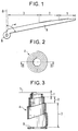
- the spring of the conical type for electrical contact of the invention is produced from a plate of uniform thickness of electrically conductive material whose mechanical characteristics effectively make it possible to produce a spring. It will be fixed on a support by a fixed end while its other end will be mobile. It is shown flat in Figure 1. It comprises an elongated body A which is a narrower electrical conductor at its movable end than at its fixed end where it is extended by a fixed contact member such as a washer B. Body A is broken down into three contiguous portions which are quadrilaterals of which one of the sides, the base, is carried by the same straight line for each of them. The first portion 1, starting with a thin edge at the first end of the body A has a width which increases linearly from this end.
- the second portion 2 also starting with a thin edge where the first portion 1 ends, has at this location a width identical to that of the first portion.
- the width of the second portion increases linearly up to its common border with the third portion, the increase in width per unit of length being less significant than in the case of the first portion.
- the third portion 3, also called segment, has a constant width equal to the maximum width of the second portion 2.
- the axis ⁇ which is in the plane of the plate, passes through the center of the washer B and makes an angle ⁇ with the bases of the three portions 1, 2, 3.
- the washer B is then folded to be perpendicular to this axis ⁇ .
- the spring thus shaped is shown seen from above, in FIG. 2, and seen in section during the start of compression in FIG. 3.
- the first portion 1 having the smallest section to length ratio, is the most flexible and the various turns which constitute it will gradually come into contact with a bearing face 5, that of 'a generator, for example, perpendicular to the axis and opposite to the washer B by which the spring is held. Then, the portion 2 will deform in turn by exerting greater pressure and also participating in contact with the bearing face 5. Finally, the portion 3, of constant section, in the final phase of compression, will provide the 'essential force applied to this bearing face.
- the embodiment described and shown in the figures can give rise to numerous variants.
- the body A of the spring which is here subdivided into three portions presenting section to defined length ratios, can take a completely different form. The important thing is that a turn will deform as much more easily that the ratio of its section to its diameter will be small.
- it is possible to choose the number of turns which will actually be in contact with the bearing face by defining the relationship which links the width of a section of the body. and the position of this section along this body.
- the fixed contact member whose function is to allow the connection of the spring to an external electrical connection has been represented by a washer B. This is not a limitation of the invention because a member of any other form can suit to fulfill this function.
- the body A of the spring is not produced from a plate but from a wire.
- This wire comprises a frustoconical part which has the same characteristic as the first 1 and second 2 portions of the previous embodiment, namely a section decreasing regularly from one to the other of its ends.
- This wire can, moreover, comprise a cylindrical part of constant section corresponding to the third portion 3 of the spring produced from a plate.
- the conical type spring object of the invention thus improves the electrical contact with the bearing face on the one hand by increasing the contact surface, on the other hand by acting on the contact pressure of each turn.
- the spring of the conical type is thus called, because according to the invention, it is not essential that the conductor is wound on a truncated cone.
- the shape of the winding can indeed be very different provided that two separate sections of the conductor in no case give orthogonal projections on the support plane 5 having a common part.
Landscapes
- Chemical & Material Sciences (AREA)
- Chemical Kinetics & Catalysis (AREA)
- Electrochemistry (AREA)
- General Chemical & Material Sciences (AREA)
- Contacts (AREA)
- Springs (AREA)
- Coupling Device And Connection With Printed Circuit (AREA)
- Manufacture Of Switches (AREA)
Applications Claiming Priority (2)
| Application Number | Priority Date | Filing Date | Title |
|---|---|---|---|
| FR9001749 | 1990-02-14 | ||
| FR9001749A FR2658365B1 (fr) | 1990-02-14 | 1990-02-14 | Ressort du type conique pour contact electrique. |
Publications (2)
| Publication Number | Publication Date |
|---|---|
| EP0442411A1 EP0442411A1 (fr) | 1991-08-21 |
| EP0442411B1 true EP0442411B1 (fr) | 1995-03-15 |
Family
ID=9393705
Family Applications (1)
| Application Number | Title | Priority Date | Filing Date |
|---|---|---|---|
| EP91101862A Expired - Lifetime EP0442411B1 (fr) | 1990-02-14 | 1991-02-11 | Ressort du type conique pour contact électrique |
Country Status (8)
| Country | Link |
|---|---|
| EP (1) | EP0442411B1 (da) |
| AT (1) | ATE120043T1 (da) |
| DE (1) | DE69108072T2 (da) |
| DK (1) | DK0442411T3 (da) |
| ES (1) | ES2070352T3 (da) |
| FI (1) | FI99059C (da) |
| FR (1) | FR2658365B1 (da) |
| NO (1) | NO180608C (da) |
Families Citing this family (2)
| Publication number | Priority date | Publication date | Assignee | Title |
|---|---|---|---|---|
| FR2806537B1 (fr) * | 2000-03-16 | 2002-06-07 | Socapex Amphenol | Connecteur electrique |
| DE102013107450B3 (de) * | 2013-07-15 | 2015-01-15 | Phoenix Contact Gmbh & Co. Kg | Elektrische Anschlussklemme |
Family Cites Families (2)
| Publication number | Priority date | Publication date | Assignee | Title |
|---|---|---|---|---|
| US3885848A (en) * | 1974-06-03 | 1975-05-27 | Corning Glass Works | Electrical connection and method of making same |
| US4554226A (en) * | 1983-10-07 | 1985-11-19 | Simonton Robert D | Flat cell battery connector seal |
-
1990
- 1990-02-14 FR FR9001749A patent/FR2658365B1/fr not_active Expired - Lifetime
-
1991
- 1991-02-11 ES ES91101862T patent/ES2070352T3/es not_active Expired - Lifetime
- 1991-02-11 FI FI910650A patent/FI99059C/fi active
- 1991-02-11 DK DK91101862.0T patent/DK0442411T3/da active
- 1991-02-11 AT AT91101862T patent/ATE120043T1/de not_active IP Right Cessation
- 1991-02-11 EP EP91101862A patent/EP0442411B1/fr not_active Expired - Lifetime
- 1991-02-11 DE DE69108072T patent/DE69108072T2/de not_active Expired - Fee Related
- 1991-02-12 NO NO910547A patent/NO180608C/no unknown
Also Published As
| Publication number | Publication date |
|---|---|
| DK0442411T3 (da) | 1995-06-19 |
| DE69108072T2 (de) | 1995-07-20 |
| FI910650A0 (fi) | 1991-02-11 |
| FI910650L (fi) | 1991-08-15 |
| NO180608C (no) | 1997-05-14 |
| ES2070352T3 (es) | 1995-06-01 |
| FI99059B (fi) | 1997-06-13 |
| NO180608B (no) | 1997-02-03 |
| FR2658365B1 (fr) | 1992-04-24 |
| ATE120043T1 (de) | 1995-04-15 |
| FR2658365A1 (fr) | 1991-08-16 |
| FI99059C (fi) | 1997-09-25 |
| NO910547L (no) | 1991-08-15 |
| DE69108072D1 (de) | 1995-04-20 |
| NO910547D0 (no) | 1991-02-12 |
| EP0442411A1 (fr) | 1991-08-21 |
Similar Documents
| Publication | Publication Date | Title |
|---|---|---|
| EP1134820B1 (fr) | Procédé de raccordement des lamelles d'une électrode à une borne d'un générateur électrochimique et générateur en résultant. | |
| EP0121467B1 (fr) | Microconnecteur à haute densité de contacts | |
| EP1042768A1 (fr) | Bobinage pour transformateur planar | |
| EP0162766B1 (fr) | Dispositif de stockage à haute tension et à haute énergie et générateur d'impulsions en comportant application | |
| EP0205360B1 (fr) | Bande de connexion pour la fabrication de composants électriques à report direct et procédé de fabrication de ces composants | |
| WO2010057950A1 (fr) | Cablage electrique dans une articulation | |
| EP2846412B1 (fr) | Connecteur électrique à effort d'insertion réduit | |
| EP0130902B1 (fr) | Composant électronique inductif pour le report à plat | |
| FR2734970A1 (fr) | Ligne de liaison electrique coaxiale | |
| EP0442411A1 (fr) | Ressort du type conique pour contact électrique | |
| EP0160594A1 (fr) | Résonateur piézo-électrique | |
| EP0238585A1 (fr) | Perfectionnements aux douilles de contact electrique | |
| FR2754393A1 (fr) | Dispositif d'introduction et de maintien d'un faisceau d'electrodes dans un conteneur de generateur electrochimique | |
| CA2085864C (fr) | Parafoudre a proprietes mecaniques perfectionnees | |
| EP0303547A1 (fr) | Transducteur omnidirectionnel d'ondes élastiques à large bande passante | |
| EP0035942B1 (fr) | Dynamomètre à fil de jauge enroulé et branché dans un montage électrique en pont | |
| WO1992014510A1 (fr) | Sonde vaginale | |
| WO1991010244A1 (fr) | Transformateur de type torique | |
| EP0340081B1 (fr) | Dispositif de tronçonnage de tubes | |
| EP1134846B1 (fr) | Connecteur électrique | |
| EP0147260B1 (fr) | Connecteur électrique à continuité de masse améliorée, et son procédé de fabrication | |
| EP0836205B1 (fr) | Procédé de bobinage de spires en couches radiales | |
| FR2820878A1 (fr) | Perfectionnement a un dispositif de manoeuvre bistable en translation d'un axe mobile | |
| EP0225206B1 (fr) | Pièce de connexion pour composant électrique | |
| EP1054187B1 (fr) | Actionneur electromagnétique |
Legal Events
| Date | Code | Title | Description |
|---|---|---|---|
| PUAI | Public reference made under article 153(3) epc to a published international application that has entered the european phase |
Free format text: ORIGINAL CODE: 0009012 |
|
| AK | Designated contracting states |
Kind code of ref document: A1 Designated state(s): AT BE CH DE DK ES FR GB GR IT LI LU NL SE |
|
| 17P | Request for examination filed |
Effective date: 19920217 |
|
| 17Q | First examination report despatched |
Effective date: 19940516 |
|
| RAP1 | Party data changed (applicant data changed or rights of an application transferred) |
Owner name: ALCATEL MOBILE COMMUNICATION FRANCE |
|
| GRAA | (expected) grant |
Free format text: ORIGINAL CODE: 0009210 |
|
| AK | Designated contracting states |
Kind code of ref document: B1 Designated state(s): AT BE CH DE DK ES FR GB GR IT LI LU NL SE |
|
| REF | Corresponds to: |
Ref document number: 120043 Country of ref document: AT Date of ref document: 19950415 Kind code of ref document: T |
|
| REF | Corresponds to: |
Ref document number: 69108072 Country of ref document: DE Date of ref document: 19950420 |
|
| ITF | It: translation for a ep patent filed | ||
| REG | Reference to a national code |
Ref country code: ES Ref legal event code: FG2A Ref document number: 2070352 Country of ref document: ES Kind code of ref document: T3 |
|
| REG | Reference to a national code |
Ref country code: DK Ref legal event code: T3 |
|
| GBT | Gb: translation of ep patent filed (gb section 77(6)(a)/1977) |
Effective date: 19950601 |
|
| REG | Reference to a national code |
Ref country code: GR Ref legal event code: FG4A Free format text: 3016345 |
|
| PLBE | No opposition filed within time limit |
Free format text: ORIGINAL CODE: 0009261 |
|
| STAA | Information on the status of an ep patent application or granted ep patent |
Free format text: STATUS: NO OPPOSITION FILED WITHIN TIME LIMIT |
|
| 26N | No opposition filed | ||
| PGFP | Annual fee paid to national office [announced via postgrant information from national office to epo] |
Ref country code: CH Payment date: 20000117 Year of fee payment: 10 |
|
| PGFP | Annual fee paid to national office [announced via postgrant information from national office to epo] |
Ref country code: SE Payment date: 20000124 Year of fee payment: 10 Ref country code: LU Payment date: 20000124 Year of fee payment: 10 |
|
| PGFP | Annual fee paid to national office [announced via postgrant information from national office to epo] |
Ref country code: AT Payment date: 20000125 Year of fee payment: 10 |
|
| PGFP | Annual fee paid to national office [announced via postgrant information from national office to epo] |
Ref country code: BE Payment date: 20000208 Year of fee payment: 10 |
|
| PGFP | Annual fee paid to national office [announced via postgrant information from national office to epo] |
Ref country code: ES Payment date: 20000217 Year of fee payment: 10 |
|
| PGFP | Annual fee paid to national office [announced via postgrant information from national office to epo] |
Ref country code: GR Payment date: 20000218 Year of fee payment: 10 |
|
| PG25 | Lapsed in a contracting state [announced via postgrant information from national office to epo] |
Ref country code: AT Free format text: LAPSE BECAUSE OF NON-PAYMENT OF DUE FEES Effective date: 20010211 Ref country code: LU Free format text: LAPSE BECAUSE OF NON-PAYMENT OF DUE FEES Effective date: 20010211 |
|
| PG25 | Lapsed in a contracting state [announced via postgrant information from national office to epo] |
Ref country code: ES Free format text: LAPSE BECAUSE OF NON-PAYMENT OF DUE FEES Effective date: 20010212 Ref country code: SE Free format text: LAPSE BECAUSE OF NON-PAYMENT OF DUE FEES Effective date: 20010212 |
|
| PG25 | Lapsed in a contracting state [announced via postgrant information from national office to epo] |
Ref country code: GR Free format text: LAPSE BECAUSE OF NON-PAYMENT OF DUE FEES Effective date: 20010228 Ref country code: LI Free format text: LAPSE BECAUSE OF NON-PAYMENT OF DUE FEES Effective date: 20010228 Ref country code: CH Free format text: LAPSE BECAUSE OF NON-PAYMENT OF DUE FEES Effective date: 20010228 Ref country code: BE Free format text: LAPSE BECAUSE OF NON-PAYMENT OF DUE FEES Effective date: 20010228 |
|
| BERE | Be: lapsed |
Owner name: ALCATEL MOBILE COMMUNICATION FRANCE Effective date: 20010228 |
|
| REG | Reference to a national code |
Ref country code: CH Ref legal event code: PL |
|
| EUG | Se: european patent has lapsed |
Ref document number: 91101862.0 |
|
| REG | Reference to a national code |
Ref country code: GB Ref legal event code: IF02 |
|
| PGFP | Annual fee paid to national office [announced via postgrant information from national office to epo] |
Ref country code: NL Payment date: 20020129 Year of fee payment: 12 |
|
| PGFP | Annual fee paid to national office [announced via postgrant information from national office to epo] |
Ref country code: DK Payment date: 20020204 Year of fee payment: 12 |
|
| REG | Reference to a national code |
Ref country code: ES Ref legal event code: FD2A Effective date: 20020916 |
|
| PG25 | Lapsed in a contracting state [announced via postgrant information from national office to epo] |
Ref country code: DK Free format text: LAPSE BECAUSE OF NON-PAYMENT OF DUE FEES Effective date: 20030228 |
|
| PG25 | Lapsed in a contracting state [announced via postgrant information from national office to epo] |
Ref country code: NL Free format text: LAPSE BECAUSE OF NON-PAYMENT OF DUE FEES Effective date: 20030901 |
|
| REG | Reference to a national code |
Ref country code: DK Ref legal event code: EBP |
|
| NLV4 | Nl: lapsed or anulled due to non-payment of the annual fee |
Effective date: 20030901 |
|
| PG25 | Lapsed in a contracting state [announced via postgrant information from national office to epo] |
Ref country code: IT Free format text: LAPSE BECAUSE OF NON-PAYMENT OF DUE FEES;WARNING: LAPSES OF ITALIAN PATENTS WITH EFFECTIVE DATE BEFORE 2007 MAY HAVE OCCURRED AT ANY TIME BEFORE 2007. THE CORRECT EFFECTIVE DATE MAY BE DIFFERENT FROM THE ONE RECORDED. Effective date: 20050211 |
|
| PGFP | Annual fee paid to national office [announced via postgrant information from national office to epo] |
Ref country code: DE Payment date: 20080219 Year of fee payment: 18 Ref country code: GB Payment date: 20080220 Year of fee payment: 18 |
|
| PGFP | Annual fee paid to national office [announced via postgrant information from national office to epo] |
Ref country code: FR Payment date: 20080214 Year of fee payment: 18 |
|
| GBPC | Gb: european patent ceased through non-payment of renewal fee |
Effective date: 20090211 |
|
| REG | Reference to a national code |
Ref country code: FR Ref legal event code: ST Effective date: 20091030 |
|
| PG25 | Lapsed in a contracting state [announced via postgrant information from national office to epo] |
Ref country code: DE Free format text: LAPSE BECAUSE OF NON-PAYMENT OF DUE FEES Effective date: 20090901 |
|
| PG25 | Lapsed in a contracting state [announced via postgrant information from national office to epo] |
Ref country code: GB Free format text: LAPSE BECAUSE OF NON-PAYMENT OF DUE FEES Effective date: 20090211 Ref country code: FR Free format text: LAPSE BECAUSE OF NON-PAYMENT OF DUE FEES Effective date: 20090302 |