EP0442429A2 - Safety catch for a carriage guided along stair rail - Google Patents
Safety catch for a carriage guided along stair rail Download PDFInfo
- Publication number
- EP0442429A2 EP0442429A2 EP91101901A EP91101901A EP0442429A2 EP 0442429 A2 EP0442429 A2 EP 0442429A2 EP 91101901 A EP91101901 A EP 91101901A EP 91101901 A EP91101901 A EP 91101901A EP 0442429 A2 EP0442429 A2 EP 0442429A2
- Authority
- EP
- European Patent Office
- Prior art keywords
- lever
- safety
- arm
- rungs
- catch
- Prior art date
- Legal status (The legal status is an assumption and is not a legal conclusion. Google has not performed a legal analysis and makes no representation as to the accuracy of the status listed.)
- Granted
Links
Images

Classifications
-
- B—PERFORMING OPERATIONS; TRANSPORTING
- B66—HOISTING; LIFTING; HAULING
- B66B—ELEVATORS; ESCALATORS OR MOVING WALKWAYS
- B66B9/00—Kinds or types of lifts in, or associated with, buildings or other structures
- B66B9/06—Kinds or types of lifts in, or associated with, buildings or other structures inclined, e.g. serving blast furnaces
- B66B9/08—Kinds or types of lifts in, or associated with, buildings or other structures inclined, e.g. serving blast furnaces associated with stairways, e.g. for transporting disabled persons
- B66B9/0807—Driving mechanisms
- B66B9/0815—Rack and pinion, friction rollers
Definitions
- the invention relates to a safety device for a guided on a railing carriage, on which a two-armed, pivotally mounted catch lever is provided, which stops the carriage by swiveling against rungs arranged transversely to the direction of the rungs at impermissibly high speed.
- a safety device for an elevator in which rotatable pendulums are attached to the side of the elevator floor, which are pivoted out when the elevator moves up or down by hitting curved elevations on the guide rails. If a predetermined maximum speed is reached during the downward movement of the elevator, the pendulums cannot return to their normal position quickly enough and then hit protrusions of the guide rail by which the elevator is stopped.
- This known device is complex and costly due to the high number of curved elevations and the additional projections required and cannot be set to different response speeds.
- the invention has for its object to show a simpler solution for a safety device for a sled guided on a railing, which also allows an advantageous setting to different response speeds.
- the object is achieved by the features specified in the characterizing part of patent claim 1. Further features are listed in the subclaims. An embodiment of the invention will now be explained on a stair lift with a load-bearing device designed as a platform or seat with reference to the drawings.
- the railing for guiding the load-bearing device - hereinafter referred to briefly as a carriage - essentially consists of a stable guide tube 1 (FIG. 1), a toothed rack 5 guided close above the floor 2 or the steps 3 and arranged between the guide tube 1 and the toothed rack 5 Rungs 7, which have the same distances in their upper area.
- a guide cage 10 is mounted on a pivot axis 12 on the base plate 9 of the sled, which carries a person seat or a platform for a disabled lift (not shown).
- Four guide rollers 14, which are adapted to the diameter of the guide tube 1, are rotatably mounted in the guide cage 10 and allow safe and smooth guidance of the slide on the guide railing.
- the carriage is supported in its lower section in the region of the rack 5 (FIG. 2) and driven at the same time.
- the rack 5 is covered over its entire length on its side facing the steps by a screen 16 (not shown in FIG. 1).
- a screen 16 (not shown in FIG. 1).
- On a strut 18 fastened to the base plate 9 are two lower support rollers 20 rotatably mounted, which run on the lower edges of the rack 5 and the screen 18.
- An electric motor 22 drives a gearwheel 24 which engages in the rack and has a lateral guide on the screen 16 via a gearbox 23.
- the carriage is supported by an upper support roller 26 on the outside of the screen 16.
- the massive catch lever 28 (FIGS. 2 and 3) is pivotably mounted on two bearing plates 30, which are fixedly connected to the base plate 9, and has a length which corresponds approximately to the mean distance between two rungs 7.
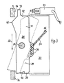
- the two-armed catch lever 28 is held in the position shown by the solid line in FIG. 3 by a tension spring 34, which is fastened on the one hand to a holding pin 35 of the one bearing plate 30 and on the other hand is suspended in one of the holes in the row of holes 36.
- an acute-angled recess 40 is worked in, which guarantees that the catch arm 39 will snap securely into the rung 7a.
- an extension 43 is provided which, when the catch lever 28 is pivoted into the latching position, serves a switch 44 for switching off the power supply to the electric motor 22 (FIG. 1) and possibly for triggering an alarm signal.
- the mountain-side catch lever arm 41 has on its side facing the rungs 7 a cam-like projection 45 which pivots the catch lever 28 when the slide descends on each rung 7 in such a way that the valley-side catch lever arm 39 enters the space between the next rung 7.
- the maximum angle of the pivoting-in process is determined by the maximum increase of the projection 45 when sliding along the long side 46 of the rung 7. As the apex of the projection 45 leaves the longitudinal side 46 of the rung 7 during the downward movement in the direction of arrow 32, the return movement of the catch lever 28 will begin under the action of the tension spring 34. Because of the inertia of the relatively massive catch lever 28, a certain time is required for the pivoting back of the catch lever, since this movement begins after the release of the projection on the rung 7 at zero and increases with the acceleration determined by the force of the tension spring 34. However, if the speed of the downward movement is greater than the defined normal speed, the catch lever 28 will not have left the area between the rungs 7 and 7a (FIG. 3) and will apply it to the rung 7a and assume the position shown in broken lines in FIG.
- the main advantage of the safety device according to the invention is the particularly cost-effective and reliable design solution that does not require any additional monitoring device.
Landscapes
- Engineering & Computer Science (AREA)
- Mechanical Engineering (AREA)
- Transportation (AREA)
- Automation & Control Theory (AREA)
- Structural Engineering (AREA)
- Types And Forms Of Lifts (AREA)
Abstract
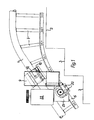
Der an einem Geländer geführte Schlitten ist mit einem massiv ausgebildeten Fanghebel (28) ausgerüstet, der quer zur Fahrtrichtung (32) schwenkbar so nahe am Geländer angeordnet ist, daß er mit seinem talseitigen Hebelarm (39) gegen die Wirkung einer Zugfeder (34) in den Bereich zwischen zwei benachbarten Sprossen (7) und (7a), die senkrecht zur Fahrtrichtung (32) am Geländer angeordnet sind, einschwenken kann. Die Zugfeder (34) versucht, den Fanghebel (28) in eine längs zur Fahrtrichtung (32) weisende Lage zu bringen. An der einen auf der zum Geländer weisenden Längsseite des Fanghebels (28) weist dieser an seinem bergseitigen Arm einen nockenartigen Vorsprung (45) auf, der den Fanghebel (28) bei einer Talfahrt an jeder Sprosse (7) so verschwenkt, daß der talseitige Arm des Fanghebels (39) in den Zwischenraum zur nächsten Sprosse (7) eintritt. Wenn die Talfahrt eine vorherbestimmte Geschwindigkeit überschreitet, kann der Fanghebel (28) aufgrund seiner Massenträgheit nicht schnell genug aus dem Bereich der Sprossen(7)austreten und stoppt den Schlitten. <IMAGE>The carriage guided on a railing is equipped with a solidly designed safety lever (28) which is arranged so that it can be swiveled transversely to the direction of travel (32) so close to the railing that its valley lever arm (39) counteracts the action of a tension spring (34) can pivot the area between two adjacent rungs (7) and (7a), which are arranged perpendicular to the direction of travel (32) on the railing. The tension spring (34) tries to bring the catch lever (28) into a position pointing longitudinally to the direction of travel (32). On one side of the safety lever (28) pointing towards the railing, this has on its arm on the mountain side a cam-like projection (45) which pivots the safety lever (28) on each rung (7) during a descent so that the arm on the valley side of the catch lever (39) enters the space between the next rung (7). If the descent exceeds a predetermined speed, the catch lever (28) cannot exit the area of the rungs (7) quickly enough due to its inertia and stops the carriage. <IMAGE>
Description
Die Erfindung betrifft eine Fangvorrichtung für einen an einem Geländer geführten Schlitten, an dem ein zweiarmiger, quer zur Fahrtrichtung schwenkbar gelagerter Fanghebel vorgesehen ist, der bei unzulässig erhöhter Geschwindigkeit den Schlitten durch Einschwenken gegen quer zur Fahrtrichtung am Geländer angeordnete Sprossen stoppt.The invention relates to a safety device for a guided on a railing carriage, on which a two-armed, pivotally mounted catch lever is provided, which stops the carriage by swiveling against rungs arranged transversely to the direction of the rungs at impermissibly high speed.
Aus der CH-PS 6617 ist bereits eine Fangvorrichtung für einen Fahrstuhl bekannt geworden, bei dem seitlich am Fahrstuhlboden drehbare Pendel angebracht sind, die bei Auf- oder Abwärtsbewegung des Fahrstuhls durch Auftreffen auf kurvenartige Erhöhungen an den Führungsschienen ausgeschwenkt werden. Wenn bei der Abwärtsbewegung des Fahrstuhls eine im voraus bestimmte Maximalgeschwindigkeit erreicht wird, können die Pendel nicht schnell genug in ihre Normallage zurückkehren und treffen dann auf Vorsprünge der Führungsschiene, durch die der Fahrstuhl angehalten wird. Diese bekannte Vorrichtung ist durch die erforderliche hohe Anzahl der kurvenartigen Erhöhungen und der zusätzlichen Vorsprünge aufwendig und kostspielig und läßt sich nicht auf unterschiedliche Ansprechgeschwindigkeiten einstellen.From CH-PS 6617 a safety device for an elevator is already known, in which rotatable pendulums are attached to the side of the elevator floor, which are pivoted out when the elevator moves up or down by hitting curved elevations on the guide rails. If a predetermined maximum speed is reached during the downward movement of the elevator, the pendulums cannot return to their normal position quickly enough and then hit protrusions of the guide rail by which the elevator is stopped. This known device is complex and costly due to the high number of curved elevations and the additional projections required and cannot be set to different response speeds.
Der Erfindung liegt die Aufgabe zugrunde, eine einfachere Lösung für eine Fangvorrichtung für einen an einem Geländer geführten Schlitten aufzuzeigen, die auch eine vorteilhafte Einstellung auf verschiedene Ansprechgeschwindigkeiten gestattet. Die gestellte Aufgabe wird durch die im Kennzeichen des Patentanspruchs 1 angegebenen Mekrmale gelöst. Weitere Merkmale sind in den Unteransprüchen aufgeführt. Ein Ausführungsbeispiel der Erfindung wird nun an einem Treppenaufzug mit einer als Plattform oder Sitz ausgebildeten Lastaufnahmeeinrichtung anhand der Zeichnungen erläutert.The invention has for its object to show a simpler solution for a safety device for a sled guided on a railing, which also allows an advantageous setting to different response speeds. The object is achieved by the features specified in the characterizing part of patent claim 1. Further features are listed in the subclaims. An embodiment of the invention will now be explained on a stair lift with a load-bearing device designed as a platform or seat with reference to the drawings.
Es zeigen:
- Fig.1
- eine vereinfachte Seitenansicht des Treppenaufzugs,
- Fig.2
- eine Frontansicht des Treppenaufzugs,teilweise geschnitten und
- Fig.3
- eine Darstellung und Lagerung des Fanghebels.
- Fig. 1
- a simplified side view of the stair lift,
- Fig. 2
- a front view of the elevator, partially cut and
- Fig. 3
- a representation and storage of the catch lever.
Das Geländer zur Führung der Lastaufnahmeeinrichtung - nachfolgend kurz als Schlitten bezeichnet - besteht im wesentlichen aus einem stabilen Führungsrohr 1 (Fig.1), einer dicht über dem Fußboden 2 oder den Treppenstufen 3 geführten Zahnstange 5 und zwischen dem Führungsrohr 1 und der Zahnstange 5 angeordneten Sprossen 7, die in ihrem oberen Bereich gleiche Abstände aufweisen. An der Grundplatte 9 des Schlittens, der einen Personensitz oder eine Plattform für einen Behindertenfahrstuhl (nicht dargestellt) trägt, ist ein Führungskäfig 10 auf einer Schwenkachse 12 gelagert. Im Führungskäfig 10 sind vier an den Durchmesser des Führungsrohres 1 angepaßte Führungsrollen 14 drehbar gelagert, die eine sichere und leichtgängige Führung des Schlittens am Führungsgeländer gestatten.The railing for guiding the load-bearing device - hereinafter referred to briefly as a carriage - essentially consists of a stable guide tube 1 (FIG. 1), a
Der Schlitten wird in seinem unteren Abschnitt im Bereich der Zahnstange 5 (Fig. 2) abgestützt und zugleich angetrieben. die Zahnstange 5 ist auf ihrer zu den Treppenstufen weisenden Seite in ihrer ganzen Länge durch eine Sichtblende 16 abgedeckt (in Fig.1 nicht dargestellt). An einer an der Grundplatte 9 befestigten Strebe 18 sind zwei untere Stützrollen 20 drehbar gelagert, die an den Unterkanten der Zahnstange 5 und der Sichtblende 18 laufen.The carriage is supported in its lower section in the region of the rack 5 (FIG. 2) and driven at the same time. The
Ein Elektromotor 22 treibt über ein Getriebe 23 ein in die Zahnstange eingreifendes Zahnrad 24 an, das an der Sichtblende 16 eine seitliche Führung besitzt. Der Schlitten stützt sich mit einer oberen Stützrolle 26 an der Außenseite der Sichtblende 16 ab.An
Der massive Fanghebel 28 (Fig.2 und 3) ist auf zwei mit der Grundplatte 9 fest verbundenen Lagerplatten 30 mit einem Lagerbolzen 31 schwenkbar gelagert und besitzt eine Länge, die etwa dem mittleren Abstand zweier Sprossen 7 entspricht. Der zweiarmige Fanghebel 28 wird durch eine Zugfeder 34, die einerseits an einem Haltestift 35 der einen Lagerplatte 30 befestigt und andererseits in eines der Löcher der Lochreihe 36 eingehängt ist, in der in Fig .3 mit ausgezogener Linie dargestellten Lage gehalten.The massive catch lever 28 (FIGS. 2 and 3) is pivotably mounted on two
An der Stirnseite 38 des talseitigen Fanghebelarms 39 ist eine spitzwinkelige Aussparung 40 eingearbeitet, die ein sicheres Einrasten des Fanghebelarms 39 an der Sprosse 7a garantiert. An der Stirnseite 42 des bergseitigen Fanghebelarms 41 ist ein Fortsatz 43 vorgesehen, der bei Schwenkung des Fanghebels 28 in die Raststellung einen Schalter 44 zur Abschaltung der Stromversorgung des Elektromotors 22 (Fig. 1) und gegebenenfalls zur Auslösung eines Alarmsignals dient. Der bergseitige Fanghebelarm 41 weist auf seiner den Sprossen 7 zugewandten Seite einen nockenartigen Vorsprung 45 auf, der den Fanghebel 28 bei einer Talfahrt des Schlittens an jeder Sprosse 7 so verschwenkt, daß der talseitige Fanghebelarm 39 in den Zwischenraum zur nächsten Sprosse 7 eintritt. Der maximale Winkel des Einschwenkvorgangs wird bestimmt durch die maximale Erhöhung des Vorsprungs 45 beim Entlanggleiten an der Längsseite 46 der Sprosse 7. Sowie der Scheitel des Vorsprungs 45 bei der Abwärtsbewegung in Richtung des Pfeiles 32 die Längsseite 46 der Sprosse 7 verläßt, wird die Rückstellbewegung des Fanghebels 28 unter der Wirkung der Zugfeder 34 einsetzen. Wegen der Massenträgheit des verhältnismäßig massiven Fanghebels 28, wird für die Rückschwenkung des Fanghebels eine bestimmte Zeit benötigt, da diese Bewegung nach der Freigabe des Vorsprungs an der Sprosse 7 bei Null beginnt und mit der durch die Kraft der Zugfeder 34 bestimmten Beschleunigung ansteigt. Ist jedoch die Geschwindigkeit der Abwärtsbewegung größer als die festgelegte Normalgeschwindigkeit, wird der Fanghebel 28 den Bereich zwischen den Sprossen 7 und 7a (Fig.3) noch nicht verlassen haben und auf die Sprosse 7a auftraffen und die in Fig.3 gestrichelt eingezeichnete Lage einnehmen.On the
Der wesentliche Vorteil der erfindungsgemäßen Fangvorrichtung ist die besonders kostengünstige und betriebssichere konstruktive Lösung, die keine weitere zusätzliche Überwachungseinrichtung erforderlich macht.The main advantage of the safety device according to the invention is the particularly cost-effective and reliable design solution that does not require any additional monitoring device.
Claims (5)
Applications Claiming Priority (2)
| Application Number | Priority Date | Filing Date | Title |
|---|---|---|---|
| DE4004190 | 1990-02-12 | ||
| DE4004190 | 1990-02-12 |
Publications (3)
| Publication Number | Publication Date |
|---|---|
| EP0442429A2 true EP0442429A2 (en) | 1991-08-21 |
| EP0442429A3 EP0442429A3 (en) | 1992-02-19 |
| EP0442429B1 EP0442429B1 (en) | 1994-11-30 |
Family
ID=6399927
Family Applications (1)
| Application Number | Title | Priority Date | Filing Date |
|---|---|---|---|
| EP91101901A Expired - Lifetime EP0442429B1 (en) | 1990-02-12 | 1991-02-11 | Safety catch for a carriage guided along stair rail |
Country Status (2)
| Country | Link |
|---|---|
| EP (1) | EP0442429B1 (en) |
| DE (1) | DE59103604D1 (en) |
Cited By (1)
| Publication number | Priority date | Publication date | Assignee | Title |
|---|---|---|---|---|
| US6659230B1 (en) * | 2000-01-17 | 2003-12-09 | Stannah Stairlifts Limited | Safety brake for stairlifts |
Families Citing this family (1)
| Publication number | Priority date | Publication date | Assignee | Title |
|---|---|---|---|---|
| CN102936959B (en) * | 2012-11-28 | 2014-11-19 | 无锡威华电焊机制造有限公司 | Device for adjusting section distance of steel bar truss |
Family Cites Families (4)
| Publication number | Priority date | Publication date | Assignee | Title |
|---|---|---|---|---|
| US4046226A (en) * | 1976-07-08 | 1977-09-06 | Flinchbaugh-Murray Corporation | Elevator system for transporting wheelchair patients |
| DE2719120C2 (en) * | 1977-04-29 | 1987-08-20 | Kleindienst GmbH, 8900 Augsburg | lift |
| EP0137577A1 (en) * | 1983-10-10 | 1985-04-17 | Antony Stopher | A stair lift |
| GB8531094D0 (en) * | 1985-12-18 | 1986-01-29 | Ease Ltd | Stairlift |
-
1991
- 1991-02-11 EP EP91101901A patent/EP0442429B1/en not_active Expired - Lifetime
- 1991-02-11 DE DE59103604T patent/DE59103604D1/en not_active Expired - Fee Related
Cited By (1)
| Publication number | Priority date | Publication date | Assignee | Title |
|---|---|---|---|---|
| US6659230B1 (en) * | 2000-01-17 | 2003-12-09 | Stannah Stairlifts Limited | Safety brake for stairlifts |
Also Published As
| Publication number | Publication date |
|---|---|
| EP0442429B1 (en) | 1994-11-30 |
| EP0442429A3 (en) | 1992-02-19 |
| DE59103604D1 (en) | 1995-01-12 |
Similar Documents
| Publication | Publication Date | Title |
|---|---|---|
| DE69611064T2 (en) | Movable fall protection device for flexible rescue rope | |
| AT504458B1 (en) | SELF-LOCKING SET AND ATTACHMENT TO SAFETY DEVICES | |
| DE60222239T2 (en) | MOVABLE FALLING SAFETY DEVICE FOR RESCUE ROPE | |
| EP0076974B1 (en) | Lifting platform for persons | |
| DE102011009049A1 (en) | Fall protection device for climbing device, particularly ladder and manhole step, comprises running rail reaching over ceiling and safety runner connected with person climbing ladder | |
| DE2753445A1 (en) | SAFETY DEVICE FOR AN ELEVATOR SYSTEM | |
| WO2020201254A1 (en) | Cable-car support comprising a climb-over apparatus | |
| DE3728282A1 (en) | Fall-prevention means, in particular for roofing work | |
| DE2807267C2 (en) | ||
| WO2000060209A1 (en) | Catching unit | |
| EP1514994B1 (en) | Catching device for a climbing safety system | |
| EP0442429B1 (en) | Safety catch for a carriage guided along stair rail | |
| WO2012175394A1 (en) | Firefighting elevator | |
| DE9013718U1 (en) | Safety device for a sledge guided on a railing | |
| DE3216231A1 (en) | Safety rope clamp for persons at risk of falling | |
| EP0129241B1 (en) | Device for moving a climbing safety arrangement from a first climbing path to a second climbing path | |
| EP0351448B1 (en) | Device for safely leaving a climbing way when turning to a platform, a building-roof, a podium or the like | |
| DE3810359C2 (en) | Motor vehicle aerial ladder with car, in particular fire aerial aerial ladder | |
| EP1780358A2 (en) | Door drive with anti-dropping device | |
| EP0187976B1 (en) | Locking device for telescopic elements of a lift | |
| DE69015001T2 (en) | Fall protection device to a ladder from a floor above. | |
| WO1992019325A1 (en) | Jumping device for sports jumping from great heights | |
| DE9107493U1 (en) | Tower crane - crane operator lift with elevator car | |
| DE3101944C2 (en) | Sunroof for buildings | |
| DE1295150B (en) | Elevator with a locking device on the lower pulley |
Legal Events
| Date | Code | Title | Description |
|---|---|---|---|
| PUAI | Public reference made under article 153(3) epc to a published international application that has entered the european phase |
Free format text: ORIGINAL CODE: 0009012 |
|
| AK | Designated contracting states |
Kind code of ref document: A2 Designated state(s): DE GB NL SE |
|
| PUAL | Search report despatched |
Free format text: ORIGINAL CODE: 0009013 |
|
| AK | Designated contracting states |
Kind code of ref document: A3 Designated state(s): DE GB NL SE |
|
| 17P | Request for examination filed |
Effective date: 19920304 |
|
| 17Q | First examination report despatched |
Effective date: 19940228 |
|
| GRAA | (expected) grant |
Free format text: ORIGINAL CODE: 0009210 |
|
| AK | Designated contracting states |
Kind code of ref document: B1 Designated state(s): DE GB NL SE |
|
| REF | Corresponds to: |
Ref document number: 59103604 Country of ref document: DE Date of ref document: 19950112 |
|
| GBT | Gb: translation of ep patent filed (gb section 77(6)(a)/1977) |
Effective date: 19950116 |
|
| NLS | Nl: assignments of ep-patents |
Owner name: GRASS GMBH |
|
| RAP2 | Party data changed (patent owner data changed or rights of a patent transferred) |
Owner name: GRASS GMBH |
|
| RIN2 | Information on inventor provided after grant (corrected) |
Free format text: GRASS, GERD |
|
| PLBE | No opposition filed within time limit |
Free format text: ORIGINAL CODE: 0009261 |
|
| STAA | Information on the status of an ep patent application or granted ep patent |
Free format text: STATUS: NO OPPOSITION FILED WITHIN TIME LIMIT |
|
| REG | Reference to a national code |
Ref country code: GB Ref legal event code: 732E |
|
| NLT2 | Nl: modifications (of names), taken from the european patent patent bulletin |
Owner name: GRASS GMBH |
|
| 26N | No opposition filed | ||
| NLS | Nl: assignments of ep-patents |
Owner name: THYSSEN TREPPENLIFTE GMBH |
|
| PGFP | Annual fee paid to national office [announced via postgrant information from national office to epo] |
Ref country code: SE Payment date: 19990111 Year of fee payment: 9 |
|
| PGFP | Annual fee paid to national office [announced via postgrant information from national office to epo] |
Ref country code: GB Payment date: 19990205 Year of fee payment: 9 |
|
| PGFP | Annual fee paid to national office [announced via postgrant information from national office to epo] |
Ref country code: NL Payment date: 19990228 Year of fee payment: 9 |
|
| PGFP | Annual fee paid to national office [announced via postgrant information from national office to epo] |
Ref country code: DE Payment date: 19990331 Year of fee payment: 9 |
|
| PG25 | Lapsed in a contracting state [announced via postgrant information from national office to epo] |
Ref country code: GB Free format text: LAPSE BECAUSE OF NON-PAYMENT OF DUE FEES Effective date: 20000211 |
|
| PG25 | Lapsed in a contracting state [announced via postgrant information from national office to epo] |
Ref country code: SE Free format text: LAPSE BECAUSE OF NON-PAYMENT OF DUE FEES Effective date: 20000212 |
|
| PG25 | Lapsed in a contracting state [announced via postgrant information from national office to epo] |
Ref country code: NL Free format text: LAPSE BECAUSE OF NON-PAYMENT OF DUE FEES Effective date: 20000901 |
|
| GBPC | Gb: european patent ceased through non-payment of renewal fee |
Effective date: 20000211 |
|
| EUG | Se: european patent has lapsed |
Ref document number: 91101901.6 |
|
| NLV4 | Nl: lapsed or anulled due to non-payment of the annual fee |
Effective date: 20000901 |
|
| PG25 | Lapsed in a contracting state [announced via postgrant information from national office to epo] |
Ref country code: DE Free format text: LAPSE BECAUSE OF NON-PAYMENT OF DUE FEES Effective date: 20001201 |