EP0442487A2 - Elément de liaison entre deux éléments de structure de construction - Google Patents
Elément de liaison entre deux éléments de structure de construction Download PDFInfo
- Publication number
- EP0442487A2 EP0442487A2 EP91102067A EP91102067A EP0442487A2 EP 0442487 A2 EP0442487 A2 EP 0442487A2 EP 91102067 A EP91102067 A EP 91102067A EP 91102067 A EP91102067 A EP 91102067A EP 0442487 A2 EP0442487 A2 EP 0442487A2
- Authority
- EP
- European Patent Office
- Prior art keywords
- connecting element
- spring
- spring tongue
- element according
- locking
- Prior art date
- Legal status (The legal status is an assumption and is not a legal conclusion. Google has not performed a legal analysis and makes no representation as to the accuracy of the status listed.)
- Granted
Links
- 238000010276 construction Methods 0.000 title 1
- 210000002105 tongue Anatomy 0.000 claims abstract description 49
- 230000008878 coupling Effects 0.000 claims abstract description 18
- 238000010168 coupling process Methods 0.000 claims abstract description 18
- 238000005859 coupling reaction Methods 0.000 claims abstract description 18
- 230000003068 static effect Effects 0.000 claims abstract description 6
- 238000000926 separation method Methods 0.000 abstract description 6
- 230000001066 destructive effect Effects 0.000 abstract 1
- XEEYBQQBJWHFJM-UHFFFAOYSA-N Iron Chemical compound [Fe] XEEYBQQBJWHFJM-UHFFFAOYSA-N 0.000 description 2
- 229910052782 aluminium Inorganic materials 0.000 description 2
- XAGFODPZIPBFFR-UHFFFAOYSA-N aluminium Chemical compound [Al] XAGFODPZIPBFFR-UHFFFAOYSA-N 0.000 description 2
- 238000004873 anchoring Methods 0.000 description 2
- 230000006378 damage Effects 0.000 description 2
- 241001295925 Gegenes Species 0.000 description 1
- 238000005452 bending Methods 0.000 description 1
- 230000006835 compression Effects 0.000 description 1
- 238000007906 compression Methods 0.000 description 1
- 230000001419 dependent effect Effects 0.000 description 1
- 230000002349 favourable effect Effects 0.000 description 1
- 229910052742 iron Inorganic materials 0.000 description 1
- 229910052751 metal Inorganic materials 0.000 description 1
- 239000002184 metal Substances 0.000 description 1
- 230000003287 optical effect Effects 0.000 description 1
- 229920000642 polymer Polymers 0.000 description 1
- 230000008092 positive effect Effects 0.000 description 1
Images
Classifications
-
- E—FIXED CONSTRUCTIONS
- E04—BUILDING
- E04B—GENERAL BUILDING CONSTRUCTIONS; WALLS, e.g. PARTITIONS; ROOFS; FLOORS; CEILINGS; INSULATION OR OTHER PROTECTION OF BUILDINGS
- E04B2/00—Walls, e.g. partitions, for buildings; Wall construction with regard to insulation; Connections specially adapted to walls
- E04B2/88—Curtain walls
- E04B2/96—Curtain walls comprising panels attached to the structure through mullions or transoms
- E04B2/967—Details of the cross-section of the mullions or transoms
Definitions
- the invention relates to a releasable, the static connection function taking over connecting element between two frame components, in particular an inner and outer post or transom of a mullion-transom facade, each of which faces a mutually facing, undercut on both sides, extending in the longitudinal direction of the profile for the positive reception of one end have the connecting element.
- the connecting element has a rotating part which can be rotated manually from the outside via a handle about its longitudinal axis in the coupling or decoupling position, in its coupling position at one end with a hammer head in an undercut groove and at its other end with anchoring means in the engages other undercut groove and can be locked in this coupling position by a rotation lock.
- the anchoring means have a slider which is arranged to be longitudinally displaceable in the groove and carries the rotating part.
- the handle consists of a spring-elastic element that is non-rotatably connected to the rotating part, which protrudes between the two components in the uncoupling position and engages behind a holder in the coupling position under bending stress.
- the invention has for its object to develop an easily assembled and non-destructively removable connector that not only takes over the static connection function between the two frame components, but also their thermal separation.
- each spring tongue has a nose-shaped or strip-shaped handle, which is a shorter distance from the other end of the connecting element in comparison to the latching nose has and protrudes in the coupling position over the outer contour of the body.
- the handle is therefore outside the assigned undercut groove of the frame component and is therefore freely accessible to a tool.
- the connecting element is characterized according to the invention by a flat, square or rectangular body which has on its two opposite flat sides each a plurality of spring tongues, each arranged in a row at a distance from one another, each around the opposite row of spring tongues about half a spring tongue distance are arranged offset. Due to the offset arrangement of the spring tongues, the connecting element can be kept very flat, which has a positive effect on the thermal separation.
- the handling that protrudes on both flat sides of the connecting element can be done with a tool, e.g. a flat iron, act together so that the associated frame component can be removed in a simple manner without destruction.
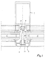
- FIG. 1 shows an inner post 1, preferably formed by an aluminum profile, which is connected to an outer post 3 via a releasable connecting element 2, which takes over the static connection function, which also preferably consists of an aluminum profile.
- Two insulating glazings 4 are clamped between the inner and outer posts 1, 3.
- Inner and outer posts 1, 3 each have a mutually facing, undercut groove 5 and 6 in the longitudinal direction of the profile, for the positive reception of one end of the connecting element 2.
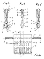
- the connecting element 2 shown in more detail in FIGS. 2 to 5 is made of plastic and has a flat body 7 which is at least approximately square in accordance with FIG. 2 and which is equipped at its lower end in the figures with spring tongues 9 forming a releasable coupling.
- These spring tongues 9 are on the two opposite flat sides 8 of the body 7 arranged in a row next to each other at a distance, the two rows of spring tongues lying opposite one another being offset from one another by about half the spring tongue distance, so that each spring tongue is arranged between two opposite spring tongues.
- Each spring tongue 9 can be pivoted about its spring tongue foot 10 lying at the extreme end of the body 7 into an inner cavity 11 of the body 7 into a decoupling position, specifically against the action of a counter spring 12 projecting into this cavity 11.
- Each spring tongue 9 is equipped with a latching lug 13 which, in the coupling position of the spring tongue 9, projects beyond the outer contour of the body 7 and engages behind the associated undercut groove 6 of the outer post 3 (see FIG. 1).
- each spring tongue 9 is pressed against the action of the counter spring 12 acting on it into said cavity 11 until the counter spring 12 engages behind the free end of the spring tongue 9 in a locking manner.
- a recess 14 is provided at the free end of each spring tongue 9, in which the counter spring 12 can engage in a locking manner.
- the latching lug 13 then lies at least largely within the outer contour of the body 7, so that the one end of the connecting element 2 can be pulled out of the groove 6 of the outer post 3.
- each spring tongue 9 has a nose-shaped or strip-shaped handle 15, which has a shorter distance from the other end of the connecting element 2 in comparison to the latching lug 13 and which is shown in FIG. 1 Clutch position protrudes beyond the outer contour of the body 7. This makes it possible, without optical control and complex manipulation, for example with flat-nose pliers, to simultaneously press the opposing spring tongues 9 into their unlocked position in the cavity 11 of the connecting element 2, where the spring tongues 9 are then automatically locked by the associated counter springs 12.
- the upper end of the connecting element 2 is designed as a resilient fork, the two spring tines 16 of which can be pressed resiliently against one another at their free end each have a detent 17 projecting in a spread coupling position over the outer contour of the body 7, which in the coupling position has the associated one reach behind the undercut groove 5 of the inner post 1 on both sides.
- the connecting element 2 is inserted with its fork tines 16 into the groove 5, the bevels provided on the latching lugs 17 leading to a compression of the fork tines 16 when the connecting element 2 is pushed in, which automatically reach the locking position when the groove bottom is reached due to their inherent elasticity rebound.
- the bolts 18 indicated in FIG. 2 are inserted between the fork tines 16.
- the bolts 18 can have longitudinal teeth 19 and can be fixed in their locking position by local brackets 20.
- the connecting element 2 combines both a thermal separation and a static connection of the metal components 1, 3, without thereby generating new cold bridges. Nevertheless, it is an easily detachable connection that can be dismantled e.g. of the outer post 3 enables without destruction.
- the spring tongues 9 engage behind the undercut groove 6 on both sides, i.e. for decoupling the spring tongues 9 provided on both flat sides 8 of the connecting element 2 must be pressed into the body 7, this body can be made very flat due to the offset arrangement of the spring tongues 9 and has in a special embodiment has a thickness of only 11.5 mm. This enables very favorable values for the thermal separation of the frame profiles.
- each spring tongue 9 lies outside the groove 6, the handles 15 are easily accessible to a tool.
Landscapes
- Engineering & Computer Science (AREA)
- Architecture (AREA)
- Physics & Mathematics (AREA)
- Electromagnetism (AREA)
- Civil Engineering (AREA)
- Structural Engineering (AREA)
- Mutual Connection Of Rods And Tubes (AREA)
- Joining Of Building Structures In Genera (AREA)
- Load-Bearing And Curtain Walls (AREA)
- Building Awnings And Sunshades (AREA)
- Electrotherapy Devices (AREA)
- Paper (AREA)
- Coupling Device And Connection With Printed Circuit (AREA)
Applications Claiming Priority (2)
| Application Number | Priority Date | Filing Date | Title |
|---|---|---|---|
| DE4004586 | 1990-02-15 | ||
| DE4004586A DE4004586A1 (de) | 1990-02-15 | 1990-02-15 | Verbindungselement zwischen zwei rahmenbauteilen |
Publications (3)
| Publication Number | Publication Date |
|---|---|
| EP0442487A2 true EP0442487A2 (fr) | 1991-08-21 |
| EP0442487A3 EP0442487A3 (en) | 1992-03-04 |
| EP0442487B1 EP0442487B1 (fr) | 1993-05-26 |
Family
ID=6400148
Family Applications (1)
| Application Number | Title | Priority Date | Filing Date |
|---|---|---|---|
| EP91102067A Expired - Lifetime EP0442487B1 (fr) | 1990-02-15 | 1991-02-14 | Elément de liaison entre deux éléments de structure de construction |
Country Status (4)
| Country | Link |
|---|---|
| EP (1) | EP0442487B1 (fr) |
| AT (1) | ATE89886T1 (fr) |
| DE (2) | DE4004586A1 (fr) |
| DK (1) | DK0442487T3 (fr) |
Cited By (5)
| Publication number | Priority date | Publication date | Assignee | Title |
|---|---|---|---|---|
| WO1999058782A1 (fr) * | 1998-05-11 | 1999-11-18 | Naimon Investments Limited | Systeme fixation de panneaux |
| WO2004088170A1 (fr) * | 2003-04-04 | 2004-10-14 | Murtfeldt Kunstostoffe Gmbh & Co. Kg | Procede et dispositif permettant de relier deux profiles de fonction differente |
| WO2018114353A1 (fr) * | 2016-12-21 | 2018-06-28 | Frener & Reifer Gmbh / Srl | Élément de fixation pour système de montants et de traverses de façade et système de montants et de traverses de façade |
| CN112031219A (zh) * | 2020-05-27 | 2020-12-04 | 浙江斯泰新材料科技股份有限公司 | 槽式埋件及其制造方法 |
| CN112982759A (zh) * | 2021-03-12 | 2021-06-18 | 中建八局第二建设有限公司 | 一种超高层单元式幕墙新型节能系统 |
Families Citing this family (10)
| Publication number | Priority date | Publication date | Assignee | Title |
|---|---|---|---|---|
| DE4105208C2 (de) * | 1991-02-20 | 1997-08-07 | Trube & Kings Kg | Pfosten- oder Riegelprofil für Gebäudefassadenkonstruktionen |
| EP0821127A3 (fr) * | 1996-07-23 | 1998-09-16 | Ulrich Knak | Dispositif pour fixer des éléments de construction plans de manière thermiquement isolante |
| DE29612381U1 (de) * | 1996-07-23 | 1996-09-12 | Knak, Ulrich-Joachim, 40723 Hilden | Vorrichtung zur thermisch isolierten Befestigung von flachen Bauelementen |
| DE19833029C2 (de) * | 1997-07-25 | 2001-05-31 | Linnenbrink Hans Josef | Vorsatzrahmen für Türen mit einem Ausschnitt |
| DE29912298U1 (de) | 1999-07-20 | 1999-12-02 | Eternit AG, 41464 Neuss | Vorrichtung zur Befestigung von Bauelementen |
| DE10058159A1 (de) * | 2000-11-22 | 2002-05-23 | Gunvar Blanck | Thermisch trennende Fassade |
| DE20305555U1 (de) * | 2003-04-04 | 2004-07-01 | Murtfeldt Kunststoffe Gmbh & Co. Kg | Vorrichtung zum Verbinden zweier Profile unterschiedlicher Funktion |
| DE102004016215B4 (de) * | 2004-04-01 | 2008-11-06 | Frener & Reifer - Metallbau Gmbh | Pfosten-Riegel-System mit geringer Ansichtsbreite |
| WO2010126433A1 (fr) * | 2009-04-28 | 2010-11-04 | Ge Healthcare Bio-Sciences Ab | Agencement de fixation pour un support de colonne |
| SE2151599A1 (en) * | 2021-12-22 | 2023-06-23 | Bark Fasadsystem Ab | Construction system comprising carrying profile and an isolating element |
Family Cites Families (3)
| Publication number | Priority date | Publication date | Assignee | Title |
|---|---|---|---|---|
| US4008552A (en) * | 1973-07-11 | 1977-02-22 | Howmet Corporation | Wall structure and elements therefor |
| US4428171A (en) * | 1982-03-12 | 1984-01-31 | Atlantic Richfield Company | Thermal storefront system |
| DE3539003C1 (de) * | 1985-11-02 | 1987-01-15 | Eltreva Ag | Rahmenkonstruktion |
-
1990
- 1990-02-15 DE DE4004586A patent/DE4004586A1/de not_active Withdrawn
-
1991
- 1991-02-14 AT AT91102067T patent/ATE89886T1/de not_active IP Right Cessation
- 1991-02-14 DK DK91102067.5T patent/DK0442487T3/da active
- 1991-02-14 EP EP91102067A patent/EP0442487B1/fr not_active Expired - Lifetime
- 1991-02-14 DE DE9191102067T patent/DE59100124D1/de not_active Expired - Fee Related
Cited By (5)
| Publication number | Priority date | Publication date | Assignee | Title |
|---|---|---|---|---|
| WO1999058782A1 (fr) * | 1998-05-11 | 1999-11-18 | Naimon Investments Limited | Systeme fixation de panneaux |
| WO2004088170A1 (fr) * | 2003-04-04 | 2004-10-14 | Murtfeldt Kunstostoffe Gmbh & Co. Kg | Procede et dispositif permettant de relier deux profiles de fonction differente |
| WO2018114353A1 (fr) * | 2016-12-21 | 2018-06-28 | Frener & Reifer Gmbh / Srl | Élément de fixation pour système de montants et de traverses de façade et système de montants et de traverses de façade |
| CN112031219A (zh) * | 2020-05-27 | 2020-12-04 | 浙江斯泰新材料科技股份有限公司 | 槽式埋件及其制造方法 |
| CN112982759A (zh) * | 2021-03-12 | 2021-06-18 | 中建八局第二建设有限公司 | 一种超高层单元式幕墙新型节能系统 |
Also Published As
| Publication number | Publication date |
|---|---|
| DK0442487T3 (da) | 1993-07-26 |
| EP0442487B1 (fr) | 1993-05-26 |
| EP0442487A3 (en) | 1992-03-04 |
| DE59100124D1 (de) | 1993-07-01 |
| DE4004586A1 (de) | 1991-08-29 |
| ATE89886T1 (de) | 1993-06-15 |
Similar Documents
| Publication | Publication Date | Title |
|---|---|---|
| EP0220389B1 (fr) | Panneau pour couvrir les murs ou les plafonds | |
| EP0442487B1 (fr) | Elément de liaison entre deux éléments de structure de construction | |
| EP0526873A1 (fr) | Assemblage de profilés, notamment en aluminium | |
| DE2809811A1 (de) | Bausatz | |
| EP0266500A2 (fr) | Moyens de connexion à recouvrement | |
| DE1140330B (de) | Bauteil aus plattenfoermigen Leichtmetall- oder Kunststoffelementen | |
| DE3609584A1 (de) | Vorrichtung zur verriegelung eines fluegelrahmens | |
| AT396384B (de) | Metallprofile zur herstellung von tueren und fenstern und aehnlichem | |
| EP0059458A1 (fr) | Dispositif de liaison | |
| DE9207859U1 (de) | Glasscheibenhalter | |
| DE69208864T2 (de) | Einrichtung zum Befestigen eines Führungsschuhs auf dem unteren Teil einer Aufzugsschiebetür | |
| EP0178369B1 (fr) | Elément de fixation | |
| DE2921599C2 (fr) | ||
| DE8134756U1 (de) | "plattenfoermiges bauelement aus hartschaumkunststoffo.dgl., insbesondere zur waermeisolierung von dach- und wandflaechen von gebaeuden" | |
| DE2302538C3 (de) | Stulpschienen-Eckverbindung, insbesondere von Treibstangenbeschlägen | |
| CH624449A5 (en) | Device for connecting a covering frame to a base frame for windows, facades or room partitions | |
| DE4315534A1 (de) | Steigleitung mit Abdeckrahmen | |
| EP0475031B1 (fr) | Mur de façade | |
| DE3200078A1 (de) | Verbindung zwischen einem ersten und einem zweiten teil | |
| DE2525968A1 (de) | Verbundprofilstab, insbesondere fuer fenster- und tuerrahmen | |
| DE102007009667A1 (de) | Profilkonstruktion | |
| DE8701626U1 (de) | Verbindungsvorrichtung zur Kupplung von lösbaren Konstruktionsteilen, insbesondere Schichtkörper-Bauteilen | |
| DE2942555A1 (de) | Wechselrahmen | |
| DE9307769U1 (de) | Vorrichtung zum Verbinden von parallel liegenden mit einer T-Nut versehenen Profilleisten | |
| DE102023136225A1 (de) | T-Verbindung und Verfahren zur Montage einer T-Verbindung |
Legal Events
| Date | Code | Title | Description |
|---|---|---|---|
| PUAI | Public reference made under article 153(3) epc to a published international application that has entered the european phase |
Free format text: ORIGINAL CODE: 0009012 |
|
| AK | Designated contracting states |
Kind code of ref document: A2 Designated state(s): AT BE CH DE DK FR GB GR IT LI LU NL |
|
| PUAL | Search report despatched |
Free format text: ORIGINAL CODE: 0009013 |
|
| AK | Designated contracting states |
Kind code of ref document: A3 Designated state(s): AT BE CH DE DK FR GB GR IT LI LU NL |
|
| 17P | Request for examination filed |
Effective date: 19920304 |
|
| 17Q | First examination report despatched |
Effective date: 19920923 |
|
| GRAA | (expected) grant |
Free format text: ORIGINAL CODE: 0009210 |
|
| AK | Designated contracting states |
Kind code of ref document: B1 Designated state(s): AT BE CH DE DK FR GB GR IT LI LU NL |
|
| REF | Corresponds to: |
Ref document number: 89886 Country of ref document: AT Date of ref document: 19930615 Kind code of ref document: T |
|
| GBT | Gb: translation of ep patent filed (gb section 77(6)(a)/1977) |
Effective date: 19930601 |
|
| REF | Corresponds to: |
Ref document number: 59100124 Country of ref document: DE Date of ref document: 19930701 |
|
| ET | Fr: translation filed | ||
| REG | Reference to a national code |
Ref country code: DK Ref legal event code: T3 |
|
| ITF | It: translation for a ep patent filed | ||
| REG | Reference to a national code |
Ref country code: GR Ref legal event code: FG4A Free format text: 3008275 |
|
| EPTA | Lu: last paid annual fee | ||
| PLBE | No opposition filed within time limit |
Free format text: ORIGINAL CODE: 0009261 |
|
| STAA | Information on the status of an ep patent application or granted ep patent |
Free format text: STATUS: NO OPPOSITION FILED WITHIN TIME LIMIT |
|
| 26N | No opposition filed | ||
| PGFP | Annual fee paid to national office [announced via postgrant information from national office to epo] |
Ref country code: FR Payment date: 19950203 Year of fee payment: 5 |
|
| PGFP | Annual fee paid to national office [announced via postgrant information from national office to epo] |
Ref country code: GB Payment date: 19950206 Year of fee payment: 5 |
|
| PGFP | Annual fee paid to national office [announced via postgrant information from national office to epo] |
Ref country code: LU Payment date: 19960101 Year of fee payment: 6 |
|
| PGFP | Annual fee paid to national office [announced via postgrant information from national office to epo] |
Ref country code: GR Payment date: 19960124 Year of fee payment: 6 |
|
| PGFP | Annual fee paid to national office [announced via postgrant information from national office to epo] |
Ref country code: BE Payment date: 19960207 Year of fee payment: 6 |
|
| PGFP | Annual fee paid to national office [announced via postgrant information from national office to epo] |
Ref country code: AT Payment date: 19960209 Year of fee payment: 6 |
|
| PG25 | Lapsed in a contracting state [announced via postgrant information from national office to epo] |
Ref country code: GB Effective date: 19960214 |
|
| PGFP | Annual fee paid to national office [announced via postgrant information from national office to epo] |
Ref country code: DK Payment date: 19960227 Year of fee payment: 6 |
|
| GBPC | Gb: european patent ceased through non-payment of renewal fee |
Effective date: 19960214 |
|
| PG25 | Lapsed in a contracting state [announced via postgrant information from national office to epo] |
Ref country code: FR Effective date: 19961031 |
|
| REG | Reference to a national code |
Ref country code: FR Ref legal event code: ST |
|
| PG25 | Lapsed in a contracting state [announced via postgrant information from national office to epo] |
Ref country code: LU Free format text: LAPSE BECAUSE OF NON-PAYMENT OF DUE FEES Effective date: 19970214 Ref country code: DK Effective date: 19970214 Ref country code: AT Effective date: 19970214 |
|
| REG | Reference to a national code |
Ref country code: DK Ref legal event code: EBP |
|
| PG25 | Lapsed in a contracting state [announced via postgrant information from national office to epo] |
Ref country code: BE Effective date: 19970228 |
|
| PGFP | Annual fee paid to national office [announced via postgrant information from national office to epo] |
Ref country code: NL Payment date: 19970228 Year of fee payment: 7 |
|
| BERE | Be: lapsed |
Owner name: ELTREVA A.G. Effective date: 19970228 |
|
| PG25 | Lapsed in a contracting state [announced via postgrant information from national office to epo] |
Ref country code: GR Free format text: THE PATENT HAS BEEN ANNULLED BY A DECISION OF A NATIONAL AUTHORITY Effective date: 19970831 |
|
| REG | Reference to a national code |
Ref country code: GR Ref legal event code: MM2A Free format text: 3008275 |
|
| PGFP | Annual fee paid to national office [announced via postgrant information from national office to epo] |
Ref country code: DE Payment date: 19980321 Year of fee payment: 8 |
|
| PGFP | Annual fee paid to national office [announced via postgrant information from national office to epo] |
Ref country code: CH Payment date: 19980401 Year of fee payment: 8 |
|
| PG25 | Lapsed in a contracting state [announced via postgrant information from national office to epo] |
Ref country code: NL Free format text: LAPSE BECAUSE OF NON-PAYMENT OF DUE FEES Effective date: 19980901 |
|
| NLV4 | Nl: lapsed or anulled due to non-payment of the annual fee |
Effective date: 19980901 |
|
| PG25 | Lapsed in a contracting state [announced via postgrant information from national office to epo] |
Ref country code: LI Free format text: LAPSE BECAUSE OF NON-PAYMENT OF DUE FEES Effective date: 19990228 Ref country code: CH Free format text: LAPSE BECAUSE OF NON-PAYMENT OF DUE FEES Effective date: 19990228 |
|
| REG | Reference to a national code |
Ref country code: CH Ref legal event code: PL |
|
| PG25 | Lapsed in a contracting state [announced via postgrant information from national office to epo] |
Ref country code: DE Free format text: LAPSE BECAUSE OF NON-PAYMENT OF DUE FEES Effective date: 19991201 |
|
| PG25 | Lapsed in a contracting state [announced via postgrant information from national office to epo] |
Ref country code: IT Free format text: LAPSE BECAUSE OF NON-PAYMENT OF DUE FEES;WARNING: LAPSES OF ITALIAN PATENTS WITH EFFECTIVE DATE BEFORE 2007 MAY HAVE OCCURRED AT ANY TIME BEFORE 2007. THE CORRECT EFFECTIVE DATE MAY BE DIFFERENT FROM THE ONE RECORDED. Effective date: 20050214 |