EP0442510B1 - Méthode et installation pour atomisation ultrasonique d'un liquide - Google Patents
Méthode et installation pour atomisation ultrasonique d'un liquide Download PDFInfo
- Publication number
- EP0442510B1 EP0442510B1 EP91102120A EP91102120A EP0442510B1 EP 0442510 B1 EP0442510 B1 EP 0442510B1 EP 91102120 A EP91102120 A EP 91102120A EP 91102120 A EP91102120 A EP 91102120A EP 0442510 B1 EP0442510 B1 EP 0442510B1
- Authority
- EP
- European Patent Office
- Prior art keywords
- frequency
- signal
- ultrasonic transducer
- control
- oscillator
- Prior art date
- Legal status (The legal status is an assumption and is not a legal conclusion. Google has not performed a legal analysis and makes no representation as to the accuracy of the status listed.)
- Expired - Lifetime
Links
Images
Classifications
-
- B—PERFORMING OPERATIONS; TRANSPORTING
- B06—GENERATING OR TRANSMITTING MECHANICAL VIBRATIONS IN GENERAL
- B06B—METHODS OR APPARATUS FOR GENERATING OR TRANSMITTING MECHANICAL VIBRATIONS OF INFRASONIC, SONIC, OR ULTRASONIC FREQUENCY, e.g. FOR PERFORMING MECHANICAL WORK IN GENERAL
- B06B1/00—Methods or apparatus for generating mechanical vibrations of infrasonic, sonic, or ultrasonic frequency
- B06B1/02—Methods or apparatus for generating mechanical vibrations of infrasonic, sonic, or ultrasonic frequency making use of electrical energy
- B06B1/0207—Driving circuits
- B06B1/0223—Driving circuits for generating signals continuous in time
- B06B1/0238—Driving circuits for generating signals continuous in time of a single frequency, e.g. a sine-wave
- B06B1/0246—Driving circuits for generating signals continuous in time of a single frequency, e.g. a sine-wave with a feedback signal
- B06B1/0253—Driving circuits for generating signals continuous in time of a single frequency, e.g. a sine-wave with a feedback signal taken directly from the generator circuit
-
- B—PERFORMING OPERATIONS; TRANSPORTING
- B06—GENERATING OR TRANSMITTING MECHANICAL VIBRATIONS IN GENERAL
- B06B—METHODS OR APPARATUS FOR GENERATING OR TRANSMITTING MECHANICAL VIBRATIONS OF INFRASONIC, SONIC, OR ULTRASONIC FREQUENCY, e.g. FOR PERFORMING MECHANICAL WORK IN GENERAL
- B06B2201/00—Indexing scheme associated with B06B1/0207 for details covered by B06B1/0207 but not provided for in any of its subgroups
- B06B2201/70—Specific application
- B06B2201/77—Atomizers
Definitions
- the invention relates to a method for triggering an ultrasonic transducer for atomizing a liquid, a trigger signal having an adjustable trigger frequency being fed to the ultrasonic transducer. It also relates to a device for controlling an ultrasonic transducer for atomizing a liquid with a controllable oscillator and a frequency tracking branch, the oscillator emitting a trigger signal with an adjustable trigger frequency and connected on the output side to the ultrasonic converter via a power amplifier, and the frequency tracking branch on the output side is connected to the frequency control input of the oscillator.
- Piezoceramic ultrasonic transducers for atomizing liquids are used in various facilities, for example in inhalation devices or in humidifiers. In the latter, water is used to humidify the air. With all these devices, it is of crucial importance that the excitation or control frequency for the ultrasound transducer is optimally adapted to it.
- the optimum operating point is understood to be the operating state with regard to the feed current, feed voltage and drive frequency, in which the volume of liquid atomized per unit of time is the greatest for a given electrical power. This optimal operating point is normally at a resonance frequency of the ultrasound transducer. Due to the installation geometry or due to deviations of the ultrasonic transducer from an ideal predefined design, the point of greatest efficiency can be shifted slightly. This can only be insufficiently recognized and corrected by the previously known control principles for the ultrasound transducer.
- the first method involves the ultrasound transducer itself as a frequency-determining element in an oscillating circuit, for example in a power oscillator.
- This principle is implemented, for example, in a commercially available ultrasonic liquid atomizer (ultrasonic atomizer EFE-HMV1R7M6E from Matsushita Electric, specification from Quick-Ohm GmbH, D-5600 Wuppertal).
- a pulse-code-modulated transmitter with its own oscillator is used, which emits ultrasonic waves with a frequency of 1.7 MHz onto a water surface via the ultrasonic transducer.
- the impact of the ultrasonic waves on the boundary layer between water and air causes the liquid to rise, which manifests itself as fine water dust or mist.
- the ultrasonic transducer is attached to the lower part of a water tank.
- One possibility for using the ultrasonic transducer as a frequency-determining element is, for example, the arrangement of the ultrasonic transducer in the feedback line of an oscillator. This is described for example in EP-A-0,240,360.
- the amplitude and phase frequency response of the ultrasound transducer is then used to pull the drive frequency emitted by the oscillator to the resonance frequency of the ultrasound transducer.
- This method has the disadvantage that the operating frequency obtained in this way is also influenced by other circuit components and can therefore be noticeably adjacent to the optimum operating frequency of the ultrasonic transducer.
- a certain vibration quality of the ultrasonic transducer is required for reliable functioning, which places high demands on the manufacturing accuracy in the manufacture of the ultrasonic transducer.
- a stable operating frequency is applied to the ultrasound transducer via a power amplifier with the aid of a separate oscillator, the frequency of which is set once.
- the optimal working frequency can now be determined and set once on the device's own oscillator for the ultrasonic transducer.
- the optimal working frequency is when the sound pressure has reached its maximum. If you run the device's own oscillator as a quartz-stabilized frequency synthesizer, you get a relatively stable control system with good efficiency.
- the disadvantage is the high manufacturing effort, which is caused by the tuning process described. Due to the fixed frequency setting, frequency deviations due to aging of the ultrasonic transducer are not compensated for. This can cause the efficiency to deteriorate over the lifetime.
- the present invention is based on the object of designing a method and a device of the type mentioned at the outset in such a way that it is possible to work at the optimum operating point, without being influenced by other circuit components and by signs of aging of the ultrasound transducer.
- tracking of the control frequency of the ultrasound transducer should be made possible during operation in such a way that the point of greatest atomization efficiency is always maintained.
- the signal tapped at the ultrasound transducer is thus demodulated and then filtered, after which a frequency control signal is formed from the demodulated and filtered signal, which is used to set the control frequency.
- direction information that is to say information about whether the current working frequency is above or below the optimal working frequency (at which optimum atomization is obtained), is obtained at least when the operation is started. This is important because the drive frequency must be reduced or increased accordingly.
- the control frequency is experimentally tuned up or down from a predetermined frequency value, and that the test obtained in the course of time -Mean value signal is examined for the presence of a maximum. If a maximum is present, the "directional information" is obtained, and the drive frequency is then tracked in the frequency range of the maximum, taking into account the "directional information” in accordance with the frequency control signal.
- the aforementioned tuning and searching for the maximum as well as the change in the control frequency is preferably carried out here with the aid of a microcomputer or microprocessor.
- the present method and the present device are based on the control of the ultrasound transducer with a control frequency that can be corrected during operation.
- a frequency is used for frequency tuning, which is directly related to the atomizing power and contains all parasitic influences.
- This is the mentioned signal tapped at the ultrasound transducer, which reflects the reflection of the ultrasound waves on the liquid surface.
- the ultrasound transducer a piezoelectric, preferably a piezoceramic ultrasound transducer, is used both for sending and for receiving.
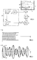
- FIG. 1 there is a liquid 4 to be atomized in a vessel 2, in front of lying water.
- the liquid surface is designated 6.
- a piezoelectric, preferably a piezoceramic, ultrasonic transducer 8 is arranged on the bottom of the vessel 2. During operation, it emits ultrasonic waves 10 in the direction of the water surface 6.
- the radiation surface of the ultrasonic transducer 8 is curved. It is used for transmitting the ultrasonic waves 10, but at the same time also for receiving the ultrasonic waves reflected on the liquid surface 6.
- the device for controlling the ultrasound transducer 8 comprises a controllable oscillator 12, which emits a control signal s with an adjustable control frequency f. It is preferably a sine wave oscillator.
- the control frequency f is in the range from 0.5 to 5 MHz, preferably in the middle range from 2.5 MHz.
- the control frequency f can be influenced by a control signal p at the frequency control input 14 of the oscillator 10.
- the oscillator 12 is connected on the output side to the input of a power amplifier 16. Its output 18 is in turn connected to the ultrasonic transducer 8.
- a frequency tracking branch 20 is also provided, which connects the output 18 of the power amplifier 16 and thus the input of the ultrasound converter 8 to the frequency control input 14 of the oscillator 12.
- this frequency tracking branch 20 comprises an amplitude demodulator 22 connected to the output 18, a downstream band filter 24 and a microprocessor 26 connected downstream thereof, the output of which is connected to the frequency control input 14 of the oscillator 12.
- the frequency range of the bandpass filter 14 is in the range from 50 Hz to 10 kHz. It is intended to filter out the area below the useful frequency of approximately 2.5 MHz in which the maximum noise lies when sputtering occurs.
- the demodulator 22 is a rectifier circuit, in particular a diode circuit.
- the ultrasonic transducer 8 is supplied via the power stage 16 with the control signal s of the adjustable control frequency f from the controllable oscillator 12.
- the ultrasound transducer 8 then sends sound waves 10 through the liquid 4 to the surface 6 thereof.
- the ultrasound waves are reflected there, and some of these reflected ultrasound waves return to the ultrasound transducer 8, where they are converted into electrical signals.
- These signals are superimposed on the control signal from the power amplifier 16 at the output 18 to the signal U.
- the signal U tapped here arrives at the amplitude demodulator 22 and from there to the downstream band filter 24.
- the envelope becomes of the output signal U, which is shown in FIGS.
- a measuring voltage or a “current mean value signal” m is obtained.
- This current mean signal m is used to control the oscillator 12. If there is "directional information" which is determined by the microprocessor 26, the signal p can be formed therefrom and from the signal m and applied to the frequency control input 14.
- the control frequency f is experimentally changed with the aid of the microprocessor 26 from a predetermined frequency value fo upwards or downwards (test run).
- a test mean signal m ' is then obtained as signal m in the course of time t. This is examined by the microprocessor 26 for the presence of a maximum.
- the microprocessor 26 also determines whether the originally specified frequency value fo is above or below the frequency f * at which the maximum of the test mean signal m 'occurs. This is the "directional information" mentioned above.
- the microprocessor 26 changes the control signal p such that the said maximum - which corresponds to the point of the greatest atomization efficiency - occurs and is then recorded.
- the control frequency f is tracked in the frequency range of the maximum in accordance with the current mean value signal m.
- the microprocessor 26 is thus able to determine that the maximum has been exceeded and is set up in such a way that the control signal p guides the control frequency f in the direction of the optimum frequency f *.
- the liquid surface 6 remains calm.
- the wave field 10 is then not disturbed, and the signal U is not subject to any change over time.
- the amplitude demodulator 22 supplies a pure DC voltage, and the measurement voltage m behind the bandpass filter 24 is almost zero.
- the signal s - in deviation from the preferred sinusoidal design - is shown as a triangular signal.
- the liquid surface 6 becomes increasingly uneasy.
- the wave field 10 is disturbed by this movement on the liquid surface 6.
- the reflected signal component is thereby modulated with a low-frequency noise, which is in particular in the range from 50 Hz to 10 kHz.
- This noise is illustrated by the envelopes h1 and h2 in FIG. 3. From this noisy signal U, the current average signal m is formed via the demodulator 22 and the bandpass filter 24, which is now no longer zero, but has a measurable value. It could be called a "noise signal”.
- this mean or measurement signal m becomes larger.
- the bandwidth of this noise signal m also increases in addition to the amplitude.
- maximum noise occurs.
- the current mean value signal or noise signal m is used by the microprocessor 26 as a control signal p for frequency control of the oscillator 12.
Landscapes
- Engineering & Computer Science (AREA)
- Mechanical Engineering (AREA)
- Special Spraying Apparatus (AREA)
Claims (7)
- Procédé d'amorçage d'un transducteur ultrasonique (8) pour une pulvérisation d'un liquide (4), où un signal d'amorçage (s) ayant une fréquence d'amorçage (f) réglable est appliqué au transducteur ultrasonique (8), caractérisé en ce que :a) un signal électrique (U) est pris à l'entrée du transducteur ultrasonique (8) le signal (U) résultant d'une combinaison du signal d'amorçage (s) et d'un signal de réflexion (r), et le signal de réflexion (r) est obtenu à partir des ondes sonores reçues en provenance du transducteur ultrasonique (8) et réfléchies sur la surface du liquide ;b) le signal (U) est démodulé et ensuite il est filtré pour former un signal de valeur moyenne (m) actuel démodulé et filtré ;c) à partir du signal (m) un signal d'amorçage de fréquence (p) est produit ; etd) au moyen du signal d'amorçage de fréquence (p), la fréquence d'amorçage (f) fait l'objet d'un suivi.
- Procédé selon la revendication 1, caractérisé en ce qu'au moins au début d'une opération de pulvérisation, à titre d'essai la fréquence d'amorçage (f) est réglée vers le haut ou vers le bas à partir d'une valeur prédéterminée de fréquence, en ce que le signal de valeur moyenne de test, obtenu au cours du temps (t), est examiné en ce qui concerne l'existence d'un maximum de façon à obtenir une information de direction, en ce que, lors de l'existence d'un maximum, le signal d'amorçage de fréquence (p) est produit à partir du signal actuel démodulé filtré (m) et à partir de l'information de direction, en ce que la fréquence d'amorçage (f), après détermination du signal d'amorçage de fréquence (p), fait ensuite l'objet d'un suivi dans la plage de fréquence du maximum.
- Procédé selon la revendication 1 ou 2, caractérisé en ce que le signal d'amorçage (s) appliqué au transducteur ultrasonique (8) a une forme sinusoïdale.
- Dispositif d'amorçage d'un transducteur ultrasonique (8) pour une pulvérisation d'un liquide, comportant un oscillateur (12) pouvant être commandé et une dérivation de suivi de fréquence (20), l'oscillateur (12) produisant un signal d'amorçage (s) ayant une fréquence d'amorçage (f) réglable et étant relié, du côté de la sortie et par l'intermédiaire d'un amplificateur de puissance (16), au transducteur ultrasonique (8) et la dérivation de suivi de fréquence est reliée du côté de sortie à l'entrée de commande de fréquence (14) de l'oscillateur (12), caractérisé en ce que le signal d'amorçage amplifié (s) est combiné avec un signal de réflexion (r) sous la forme d'un signal électrique (U), le signal de réflexion (r) est déterminé à partir des ondes sonores reçues par le transducteur ultrasonique et réfléchies sur la surface de liquide et en ce que la dérivation de suivi de fréquence (20) comporte en série un démodulateur d'amplitude (22), un filtre à bande (24) un microprocesseur (26) et elle reçoit à son entrée le signal (U).
- Dispositif selon la revendication 4, caractérisé en ce que le transducteur ultrasonique (8) est un transducteur ultrasonique piézoélectrique, de préférence piézocéramique.
- Dispositif selon la revendication 4 ou 5, caractérisé en ce que l'oscillateur (12) est un oscillateur sinusoïdal.
- Dispositif selon une des revendications 4 à 6, caractérisé en ce que la fréquence fournie par l'oscillateur (12) a une valeur comprise entre 0,5 et 5 MHz et en ce que la plage de fréquence du filtre à bande (24) est comprise entre 50 Hz et 10 kHz.
Applications Claiming Priority (2)
| Application Number | Priority Date | Filing Date | Title |
|---|---|---|---|
| DE4004541A DE4004541A1 (de) | 1990-02-14 | 1990-02-14 | Verfahren und einrichtung fuer die ultraschall-fluessigkeits-zerstaeubung |
| DE4004541 | 1990-02-14 |
Publications (2)
| Publication Number | Publication Date |
|---|---|
| EP0442510A1 EP0442510A1 (fr) | 1991-08-21 |
| EP0442510B1 true EP0442510B1 (fr) | 1995-01-25 |
Family
ID=6400130
Family Applications (1)
| Application Number | Title | Priority Date | Filing Date |
|---|---|---|---|
| EP91102120A Expired - Lifetime EP0442510B1 (fr) | 1990-02-14 | 1991-02-14 | Méthode et installation pour atomisation ultrasonique d'un liquide |
Country Status (3)
| Country | Link |
|---|---|
| EP (1) | EP0442510B1 (fr) |
| AT (1) | ATE117599T1 (fr) |
| DE (2) | DE4004541A1 (fr) |
Cited By (18)
| Publication number | Priority date | Publication date | Assignee | Title |
|---|---|---|---|---|
| US11131000B1 (en) | 2020-06-01 | 2021-09-28 | Shaheen Innovations Holding Limited | Infectious disease screening device |
| US11181451B1 (en) | 2020-06-01 | 2021-11-23 | Shaheen Innovations Holding Limited | Infectious disease screening system |
| US11571022B2 (en) | 2019-12-15 | 2023-02-07 | Shaheen Innovations Holding Limited | Nicotine delivery device |
| US11665483B1 (en) | 2021-12-15 | 2023-05-30 | Shaheen Innovations Holding Limited | Apparatus for transmitting ultrasonic waves |
| US11660406B2 (en) | 2019-12-15 | 2023-05-30 | Shaheen Innovations Holding Limited | Mist inhaler devices |
| US11672928B2 (en) | 2019-12-15 | 2023-06-13 | Shaheen Innovations Holding Limited | Mist inhaler devices |
| US11700882B2 (en) | 2019-12-15 | 2023-07-18 | Shaheen Innovations Holding Limited | Hookah device |
| US11730191B2 (en) | 2019-12-15 | 2023-08-22 | Shaheen Innovations Holding Limited | Hookah device |
| US11911559B2 (en) | 2019-12-15 | 2024-02-27 | Shaheen Innovations Holding Limited | Ultrasonic mist inhaler |
| US11944120B2 (en) | 2019-12-15 | 2024-04-02 | Shaheen Innovations Holding Limited | Ultrasonic mist inhaler with capillary retainer |
| US11944121B2 (en) | 2019-12-15 | 2024-04-02 | Shaheen Innovations Holding Limited | Ultrasonic mist inhaler with capillary element |
| US12016381B2 (en) | 2019-12-15 | 2024-06-25 | Shaheen Innovations Holding Limited | Hookah device |
| US12121056B2 (en) | 2019-12-15 | 2024-10-22 | Shaheen Innovations Holding Limited | Hookah device |
| US12156542B2 (en) | 2019-06-20 | 2024-12-03 | Shaheen Innovations Holding Limited | Personal ultrasonic atomizer device able to control the amount of liquid flow |
| US12213516B2 (en) | 2019-12-15 | 2025-02-04 | Shaheen Innovations Holding Limited | Ultrasonic mist inhaler |
| US12233207B2 (en) | 2019-12-15 | 2025-02-25 | Shaheen Innovations Holding Limited | Mist inhaler devices |
| US12262738B2 (en) | 2019-12-15 | 2025-04-01 | Shaheen Innovations Holding Limited | Ultrasonic mist inhaler |
| US12538944B2 (en) | 2019-12-15 | 2026-02-03 | Shaheen Innovations Holding Limited | Nicotine delivery device with identification arrangement |
Families Citing this family (7)
| Publication number | Priority date | Publication date | Assignee | Title |
|---|---|---|---|---|
| FR2686805A1 (fr) * | 1992-02-04 | 1993-08-06 | Kodak Pathe | Dispositif permettant de dissoudre des bulles gazeuses contenues dans une composition liquide utilisable notamment pour les produits photographiques. |
| US5563811A (en) * | 1993-04-29 | 1996-10-08 | Humonics International Inc. | Microprocessor controlled drive circuit for a liquid nebulizer having a plurality of oscillators |
| DE19962280A1 (de) * | 1999-12-23 | 2001-07-12 | Draeger Medizintech Gmbh | Ultraschallvernebler |
| DE102006054826A1 (de) * | 2006-11-21 | 2008-05-29 | Health & Life Co., Ltd., Chung Ho | Piezoelektrisches Erzeugungssystem und Erzeugungsverfahren dafür |
| DE102007002315A1 (de) * | 2007-01-16 | 2008-07-24 | Health & Life Co., Ltd., Chung Ho | Piezoelektrisches Antriebssystem |
| ATE523262T1 (de) | 2007-10-10 | 2011-09-15 | Ep Systems Sa | Adaptives steuersystem für einen piezoelektrischen aktor |
| TWI572412B (zh) | 2015-02-16 | 2017-03-01 | 台達電子工業股份有限公司 | 噴霧驅動裝置及噴霧系統 |
Family Cites Families (6)
| Publication number | Priority date | Publication date | Assignee | Title |
|---|---|---|---|---|
| JPS53127709A (en) * | 1977-04-13 | 1978-11-08 | Morita Mfg | Driving system for transducer with resonance circuit |
| US4338576A (en) * | 1978-07-26 | 1982-07-06 | Tdk Electronics Co., Ltd. | Ultrasonic atomizer unit utilizing shielded and grounded elements |
| JPS5836684A (ja) * | 1981-08-28 | 1983-03-03 | 有限会社大岳製作所 | 超音波発振法およびマイクロコンピユ−タ−内蔵超音波発振器 |
| US4687962A (en) * | 1986-12-15 | 1987-08-18 | Baxter Travenol Laboratories, Inc. | Ultrasonic horn driving apparatus and method with active frequency tracking |
| CS550488A3 (en) * | 1987-08-17 | 1992-11-18 | Satronic Ag | Ultrasonic generator circuitry |
| US4808948A (en) * | 1987-09-28 | 1989-02-28 | Kulicke And Soffa Indusries, Inc. | Automatic tuning system for ultrasonic generators |
-
1990
- 1990-02-14 DE DE4004541A patent/DE4004541A1/de not_active Withdrawn
-
1991
- 1991-02-14 EP EP91102120A patent/EP0442510B1/fr not_active Expired - Lifetime
- 1991-02-14 AT AT91102120T patent/ATE117599T1/de not_active IP Right Cessation
- 1991-02-14 DE DE59104350T patent/DE59104350D1/de not_active Expired - Fee Related
Cited By (46)
| Publication number | Priority date | Publication date | Assignee | Title |
|---|---|---|---|---|
| US12156542B2 (en) | 2019-06-20 | 2024-12-03 | Shaheen Innovations Holding Limited | Personal ultrasonic atomizer device able to control the amount of liquid flow |
| US11832646B2 (en) | 2019-12-15 | 2023-12-05 | Shaheen Innovations Holding Limited | Nicotine delivery device with identification arrangement |
| US11730899B2 (en) | 2019-12-15 | 2023-08-22 | Shaheen Innovations Holding Limited | Mist inhaler devices |
| US12538944B2 (en) | 2019-12-15 | 2026-02-03 | Shaheen Innovations Holding Limited | Nicotine delivery device with identification arrangement |
| US11571022B2 (en) | 2019-12-15 | 2023-02-07 | Shaheen Innovations Holding Limited | Nicotine delivery device |
| US11589610B2 (en) | 2019-12-15 | 2023-02-28 | Shaheen Innovations Holding Limited | Nicotine delivery device having a mist generator device and a driver device |
| US11602165B2 (en) | 2019-12-15 | 2023-03-14 | Shaheen Innovations Holding Limited | Nicotine delivery device having a mist generator device and a driver device |
| US12434021B2 (en) | 2019-12-15 | 2025-10-07 | Shaheen Innovations Holding Limited | Mist inhaler devices for delivering CBD |
| US11660406B2 (en) | 2019-12-15 | 2023-05-30 | Shaheen Innovations Holding Limited | Mist inhaler devices |
| US12434019B2 (en) | 2019-12-15 | 2025-10-07 | Shaheen Innovations Holding Limited | Mist inhaler devices for delivering nicotine |
| US11666713B2 (en) | 2019-12-15 | 2023-06-06 | Shaheen Innovations Holding Limited | Mist inhaler devices |
| US11672928B2 (en) | 2019-12-15 | 2023-06-13 | Shaheen Innovations Holding Limited | Mist inhaler devices |
| US11700882B2 (en) | 2019-12-15 | 2023-07-18 | Shaheen Innovations Holding Limited | Hookah device |
| US11717623B2 (en) | 2019-12-15 | 2023-08-08 | Shaheen Innovations Holding Limited | Mist inhaler devices |
| US11944120B2 (en) | 2019-12-15 | 2024-04-02 | Shaheen Innovations Holding Limited | Ultrasonic mist inhaler with capillary retainer |
| US11730193B2 (en) | 2019-12-15 | 2023-08-22 | Shaheen Innovations Holding Limited | Hookah device |
| US11911559B2 (en) | 2019-12-15 | 2024-02-27 | Shaheen Innovations Holding Limited | Ultrasonic mist inhaler |
| US11730191B2 (en) | 2019-12-15 | 2023-08-22 | Shaheen Innovations Holding Limited | Hookah device |
| US11744963B2 (en) | 2019-12-15 | 2023-09-05 | Shaheen Innovations Holding Limited | Mist inhaler devices |
| US11785985B2 (en) | 2019-12-15 | 2023-10-17 | Shaheen Innovations Holding Limited | Hookah device |
| US11819054B2 (en) | 2019-12-15 | 2023-11-21 | Shaheen Innovations Holding Limited | Nicotine delivery device with airflow arrangement |
| US11819607B2 (en) | 2019-12-15 | 2023-11-21 | Shaheen Innovations Holding Limited | Mist inhaler devices |
| US12434020B2 (en) | 2019-12-15 | 2025-10-07 | Shaheen Innovations Holding Limited | Mist inhaler devices for delivering medical drugs |
| US12403272B2 (en) | 2019-12-15 | 2025-09-02 | Shaheen Innovations Holding Limted | Ultrasonic mist inhaler |
| US11878112B2 (en) | 2019-12-15 | 2024-01-23 | Shaheen Innovations Holding Limited | Mist inhaler devices |
| US11724047B2 (en) | 2019-12-15 | 2023-08-15 | Shaheen Innovations Holding Limited | Mist inhaler devices |
| US11944121B2 (en) | 2019-12-15 | 2024-04-02 | Shaheen Innovations Holding Limited | Ultrasonic mist inhaler with capillary element |
| US12290098B2 (en) | 2019-12-15 | 2025-05-06 | Shaheen Innovations Holding Limited | Ultrasonic mist inhaler with capillary retainer |
| US12262738B2 (en) | 2019-12-15 | 2025-04-01 | Shaheen Innovations Holding Limited | Ultrasonic mist inhaler |
| US12016381B2 (en) | 2019-12-15 | 2024-06-25 | Shaheen Innovations Holding Limited | Hookah device |
| US12016380B2 (en) | 2019-12-15 | 2024-06-25 | Shaheen Innovations Holding Limited | Hookah device |
| US12023438B2 (en) | 2019-12-15 | 2024-07-02 | Shaheen Innovations Holding Limited | Mist inhaler devices |
| US12121056B2 (en) | 2019-12-15 | 2024-10-22 | Shaheen Innovations Holding Limited | Hookah device |
| US12137733B2 (en) | 2019-12-15 | 2024-11-12 | Shaheen Innovations Holding Limited | Hookah device |
| US12262746B2 (en) | 2019-12-15 | 2025-04-01 | Shaheen Innovations Holding Limited | Ultrasonic mist inhaler for atomizing a liquid by ultrasonic vibrations |
| US12201144B2 (en) | 2019-12-15 | 2025-01-21 | Shaheen Innovations Holding Limited | Hookah device |
| US12213516B2 (en) | 2019-12-15 | 2025-02-04 | Shaheen Innovations Holding Limited | Ultrasonic mist inhaler |
| US12233207B2 (en) | 2019-12-15 | 2025-02-25 | Shaheen Innovations Holding Limited | Mist inhaler devices |
| US11181451B1 (en) | 2020-06-01 | 2021-11-23 | Shaheen Innovations Holding Limited | Infectious disease screening system |
| US11959146B2 (en) | 2020-06-01 | 2024-04-16 | Shaheen Innovations Holding Limited | Infectious disease screening device |
| US11946844B2 (en) | 2020-06-01 | 2024-04-02 | Shaheen Innovations Holding Limited | Infectious disease screening system |
| US11274352B2 (en) | 2020-06-01 | 2022-03-15 | Shaheen Innovations Holding Limited | Infectious disease screening device |
| US11131000B1 (en) | 2020-06-01 | 2021-09-28 | Shaheen Innovations Holding Limited | Infectious disease screening device |
| US11667979B2 (en) | 2020-06-01 | 2023-06-06 | Shaheen Innovations Holding Limited | Infectious disease screening device |
| US11385148B2 (en) | 2020-06-01 | 2022-07-12 | Shaheen Innovations Holding Limited | Infectious disease screening system |
| US11665483B1 (en) | 2021-12-15 | 2023-05-30 | Shaheen Innovations Holding Limited | Apparatus for transmitting ultrasonic waves |
Also Published As
| Publication number | Publication date |
|---|---|
| ATE117599T1 (de) | 1995-02-15 |
| DE59104350D1 (de) | 1995-03-09 |
| DE4004541A1 (de) | 1991-08-22 |
| EP0442510A1 (fr) | 1991-08-21 |
Similar Documents
| Publication | Publication Date | Title |
|---|---|---|
| EP0442510B1 (fr) | Méthode et installation pour atomisation ultrasonique d'un liquide | |
| DE2641901C2 (de) | Verfahren und Vorrichtung zum Untersuchen von Objekten mittels Ultraschall | |
| DE3807004C2 (fr) | ||
| DE3816208C2 (fr) | ||
| DE19962280A1 (de) | Ultraschallvernebler | |
| DE3331896C2 (fr) | ||
| DE3783748T2 (de) | Antriebsgeraet fuer ein ultraschallhorn und verfahren mit aktivem frequenznachlauf. | |
| DE69605170T2 (de) | Verfahren und Vorrichtung zur Ansteuerung von Leistungs-Ultraschallgebern | |
| EP1558315A1 (fr) | Appareil de therapie par inhalation | |
| DE2524862A1 (de) | Schwingungserzeuger fuer einen fluessigkeitszerstaeuber | |
| DE3828591A1 (de) | Einspritzventil fuer brennkraftmaschinen | |
| EP0340470A1 (fr) | Procédé et circuit pour exciter un transducteur par ultrasons, et leur utilisation pour l'atomisation d'un liquide | |
| EP2311427B1 (fr) | Appareil de traitement à ultrasons et son procédé de fonctionnement | |
| WO1986002539A1 (fr) | Dispositif pour localiser des objets metalliques dans le corps humain ou animal | |
| CH700508B1 (de) | Hornanordnung zur Verwendung beim Ultraschallschweissen. | |
| DE2415481A1 (de) | Ultraschallgenerator | |
| WO2016016025A1 (fr) | Dispositif de traitement par ultrasons de matières comportant un dispositif de déclenchement | |
| EP0303944A1 (fr) | Procédé et circuit pour l'excitation d'un vibrateur ultrasonore et leur application à la pulvérisation d'un liquide | |
| DE3013964C2 (de) | Ultraschallgenerator | |
| EP0997747B1 (fr) | Méthode pour optimiser l'opération d'un commutateur de proximité et commutateur de proximité à opération optimisée | |
| DE3134985A1 (de) | Vorrichtung zum betrieb von resonanzdurchflussmessern | |
| EP1684046B1 (fr) | Procédé et dispositif de mesure de la distance entre une électrode de détection et une pièce à usiner | |
| EP1977190B1 (fr) | Appareil de mesure de distance | |
| DE2947143C2 (de) | Füllstandswächter eines Ultraschallzerstäubers | |
| DE2422808A1 (de) | Verfahren und anordnung zur leistungssteuerung eines hochfrequenz-generators fuer katodenzerstaeubungsanlagen |
Legal Events
| Date | Code | Title | Description |
|---|---|---|---|
| PUAI | Public reference made under article 153(3) epc to a published international application that has entered the european phase |
Free format text: ORIGINAL CODE: 0009012 |
|
| AK | Designated contracting states |
Kind code of ref document: A1 Designated state(s): AT BE CH DE ES FR GB GR IT LI LU NL SE |
|
| 17P | Request for examination filed |
Effective date: 19910917 |
|
| 17Q | First examination report despatched |
Effective date: 19931027 |
|
| GRAA | (expected) grant |
Free format text: ORIGINAL CODE: 0009210 |
|
| AK | Designated contracting states |
Kind code of ref document: B1 Designated state(s): AT BE CH DE ES FR GB GR IT LI LU NL SE |
|
| PG25 | Lapsed in a contracting state [announced via postgrant information from national office to epo] |
Ref country code: IT Free format text: LAPSE BECAUSE OF FAILURE TO SUBMIT A TRANSLATION OF THE DESCRIPTION OR TO PAY THE FEE WITHIN THE PRE;WARNING: LAPSES OF ITALIAN PATENTS WITH EFFECTIVE DATE BEFORE 2007 MAY HAVE OCCURRED AT ANY TIME BEFORE 2007. THE CORRECT EFFECTIVE DATE MAY BE DIFFERENT FROM THE ONE RECORDED.SCRIBED TIME-LIMIT Effective date: 19950125 Ref country code: BE Effective date: 19950125 Ref country code: ES Free format text: THE PATENT HAS BEEN ANNULLED BY A DECISION OF A NATIONAL AUTHORITY Effective date: 19950125 Ref country code: FR Effective date: 19950125 Ref country code: GR Free format text: LAPSE BECAUSE OF FAILURE TO SUBMIT A TRANSLATION OF THE DESCRIPTION OR TO PAY THE FEE WITHIN THE PRESCRIBED TIME-LIMIT Effective date: 19950125 Ref country code: GB Effective date: 19950125 Ref country code: NL Effective date: 19950125 |
|
| REF | Corresponds to: |
Ref document number: 117599 Country of ref document: AT Date of ref document: 19950215 Kind code of ref document: T |
|
| PG25 | Lapsed in a contracting state [announced via postgrant information from national office to epo] |
Ref country code: AT Effective date: 19950214 |
|
| PG25 | Lapsed in a contracting state [announced via postgrant information from national office to epo] |
Ref country code: CH Effective date: 19950228 Ref country code: LU Free format text: LAPSE BECAUSE OF NON-PAYMENT OF DUE FEES Effective date: 19950228 Ref country code: LI Effective date: 19950228 |
|
| REF | Corresponds to: |
Ref document number: 59104350 Country of ref document: DE Date of ref document: 19950309 |
|
| PG25 | Lapsed in a contracting state [announced via postgrant information from national office to epo] |
Ref country code: SE Effective date: 19950425 |
|
| EN | Fr: translation not filed | ||
| NLV1 | Nl: lapsed or annulled due to failure to fulfill the requirements of art. 29p and 29m of the patents act | ||
| GBV | Gb: ep patent (uk) treated as always having been void in accordance with gb section 77(7)/1977 [no translation filed] |
Effective date: 19950125 |
|
| PG25 | Lapsed in a contracting state [announced via postgrant information from national office to epo] |
Ref country code: DE Effective date: 19951101 |
|
| PLBE | No opposition filed within time limit |
Free format text: ORIGINAL CODE: 0009261 |
|
| STAA | Information on the status of an ep patent application or granted ep patent |
Free format text: STATUS: NO OPPOSITION FILED WITHIN TIME LIMIT |
|
| 26N | No opposition filed |