EP0442682A2 - System and method for displaying of colour images - Google Patents
System and method for displaying of colour images Download PDFInfo
- Publication number
- EP0442682A2 EP0442682A2 EP91301074A EP91301074A EP0442682A2 EP 0442682 A2 EP0442682 A2 EP 0442682A2 EP 91301074 A EP91301074 A EP 91301074A EP 91301074 A EP91301074 A EP 91301074A EP 0442682 A2 EP0442682 A2 EP 0442682A2
- Authority
- EP
- European Patent Office
- Prior art keywords
- colour
- pixels
- imaged
- values
- pixel
- Prior art date
- Legal status (The legal status is an assumption and is not a legal conclusion. Google has not performed a legal analysis and makes no representation as to the accuracy of the status listed.)
- Granted
Links
Images


Classifications
-
- G—PHYSICS
- G06—COMPUTING OR CALCULATING; COUNTING
- G06F—ELECTRIC DIGITAL DATA PROCESSING
- G06F17/00—Digital computing or data processing equipment or methods, specially adapted for specific functions
- G06F17/10—Complex mathematical operations
- G06F17/17—Function evaluation by approximation methods, e.g. inter- or extrapolation, smoothing, least mean square method
- G06F17/175—Function evaluation by approximation methods, e.g. inter- or extrapolation, smoothing, least mean square method of multidimensional data
Definitions
- the present invention relates generally to the area of computer graphics and more particularly to methods and means for displaying of colour images on display hardware.
- “Rendering of geometry” is a method in which objects to be displayed on the screen are expressed as polygons. Vertices of these polygons have associated colour values determined by calculations (lighting operations) performed at each rendering. Pixels, chosen at each rendering, are given these colour values to display the vertices. Remaining pixels are given colour values via "shading".
- “Shading” is the process of filling in the rest of the pixels that comprise a polygon during “rendering of geometry.” Color values for these pixels are calculated from information known about the vertices of the polygon. “Gouraud shading” is one method of shading in which the colour values of the vertices are colour interpolated to derive the colour values for the remaining pixels of the polygon. There are other methods of shading which do not involve colour interpolation. In contrast to "rendering of geometry,” pixels may be given colour values by simply filling them in from an array of colour values called an "image.” In this case there are no established objects or polygons expressed to the display hardware.
- Such an image may have been obtained from a camera, or from a process of calculating colour values such as "ray tracing.”
- "Ray tracing” is a computation intensive method of calculating colour values for a pixel.
- a computer system central processing unit CPU
- the CPU performs all of the imaging (ray tracing) computations for each and every pixel on a display screen in sequential order.
- imaging computations in general and ray tracing in particular are extremely time consuming and may take a matter of hours, or even days to complete this colour imaging, depending upon the description of the screen being displayed.
- the combination of calculating and displaying an image may be called "colour imaging.”
- Gouraud shading is a graphics technique unrelated to colour imaging, or ray tracing. Since Gouraud shading is implemented through colour interpolation, these display adapters are capable of performing colour interpolation.
- the present invention utilizes this colour interpolation capability to achieve a goal not contemplated by the conventional and standard uses of Gouraud shading.
- the present invention provides a method of displaying a colour image by interpolating pixel colour values, said method comprising the steps of: determining a number of pixels to be colour imaged; computing colour imaged values for each of said pixels included within the determined number; and using the colour imaged values to interpolate colour values for each pixel not included within the determined number.
- the present invention provides a system for displaying a colour image by interpolating pixel colour values, comprising: interface means (22) responsive to user input to determine a number of pixels to be colour imaged; a processing unit (18) to compute colour imaged values for each of said pixels included within the determined number; and interpolation means (12) for using the colour imaged values to interpolate colour values for each pixel not included within the determined number.
- the present invention allows a microprocessor included within an associated display adapter to be used to alleviate a portion of the computational burden imposed upon the system CPU during colour imaging calculations.
- the present invention utilizes the colour interpolation capability of associated display hardware to increase the speed of a computer graphics system performing colour imaging.
- the system CPU performs colour imaging (e.g. ray tracing) on a predetermined plurality of pixels.
- the CPU transmits the (r,g,b) values for each of these pixels to the processor of the display adapter hardware.
- the transmission i.e. communication between the CPU and display adapter
- the display adapter processor Upon receipt of these pixel colour values, the display adapter processor then performs colour interpolation for all of the pixels included within a geometric figure bounded by the colour imaged pixels.
- a computer graphics user that wishes to perform lighting calculations will utilize a three-dimensional (3D) display adapter hardware device 16, such as a 2781 (High-Performance 3D Color Graphics Processor), sold by IBM. Included within the 3D lighting hardware is a portion which is dedicated to performing shading operations. Usually, this shading hardware supports Gouraud shading, as discussed above, however other shading hardware utilizing colour interpolation methods are contemplated by the scope of the present invention.
- the shading hardware is utilized as a hardware assist to aid the system CPU in achieving the desired lighting of a displayed image.
- the present invention utilizes this hardware assist capability during non-lighting calculations, in particular during colour imaging, such as ray tracing operations.
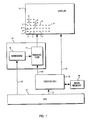
- a display 10 such as a CRT, or the like is shown having a plurality of picture elements (pixels) which are depicted by reference numerals 1, 2, 3, 4, 5, 6, 7, 8, 9, 11, 13 and N.
- a display adapter 16 typically used for performing rendering of geometry is illustrated and includes a shading processor 12 and all other associated hardware 14. This hardware may include buffers, such as a frame buffer, window buffer, Z-buffer or the like.
- a system CPU 18 is provided which performs all colour imaging, such as ray tracing calculations. Also shown in Figure 1 is the system main memory 20. It should be noted that the present invention is suited for use in all types of colour imaging applications, however ray tracing is the primary method discussed herein.
- an application program interface (API) 22 via bus 26, instructs the 3D lighting display adapter 16 to perform rendering of geometry. This may include determining the location and consequences of a light source, as well as colour interpolating a surface for shading purposes. It should be noted that in conventional systems, no colour imaging is performed by CPU 18 during rendering of geometry. Similarly, no rendering of geometry can be performed by prior art systems during the time colour imaging computations are being implemented by CPU 18.
- API application program interface
- a scene description is first stored in main memory 20.
- This scene description is a textual, or alphanumeric representation of the scene to be displayed.
- a scene description will include geometric descriptions of all objects as well as their colour (r,g,b) values and surface type. Additionally, the nature of each object, is included within the scene description, that is, whether the object is transparent, opaque, reflective or the like.
- a program application user via API 22 and bus 23, instructs the system CPU 18 to perform a series of vector (ray) calculations for each pixel on display 10.
- System CPU 18 begins at pixel 1 and back traces a ray from a view point directly in front of that pixel, through the pixel in the image plane, and into the scene. For example, if a ray 1 (corresponding to pixel 1) is found to initially intersect the surface of the ocean, then a lighting calculation is computed at the point of intersection between ray 1 and the surface and CPU 18 colours pixel 1 the computed shade.
- CPU 18 Upon implementation of a ray tracing operation, a program application user, via API 22 and bus 23, instructs the system CPU 18 to perform a series of vector (ray) calculations for each pixel on display 10.
- System CPU 18 begins at pixel 1 and back traces a ray from a view point directly in front of that pixel, through the pixel in the image plane, and into the scene. For example, if a ray 1 (corresponding to pixel 1) is
- the ray tracing calculation includes back tracing along a first ray from the view point through pixel N to the point of intersection with the reflective surface, calculating the angle of reflection to create a reflection ray which is then traced to find its nearest intersection with an object. These reflection rays are created and traced until an intersection is found with a non-reflective object, at which point a shadow ray is created which is a ray from the point of intersection to the light source. If any intervening intersections are found along this ray, i.e. intersection with other objects, then the primary intersection point is found to be in a shadow and the lighting calculation performed by the CPU 18 is adjusted accordingly. Upon completion of the lighting calculation at this point of intersection, pixel N is coloured with the calculated shade.
- the CPU 18 Upon completion of the ray tracing computation, the CPU 18 then transmits, via bus 24, the calculated colour for that pixel to the display 10. Again, during the ray tracing calculation, display adapter 16, including shading processor 12 remains idle.
- a preferred embodiment of the present invention utilizes shading processor 12 to colour a percentage of an image's pixels through colour interpolations of a subset of the ray traced pixels.
- a number of display adapters such as the aforementioned 3D lighting hardware 16, are capable of filling (colouring) polygons onto display 10.
- CPU 18 resolves individual pixels, as specified by a program application and then turns these pixels directly over to the CRT 10 for display.
- adapter 16 through shading processor 12, is capable of colouring polygons by interpolation methods, such as Gouraud shading, or the like.
- these polygons are simple polygons, such as squares, rectangles, triangles, and trapezoids. Therefore, the present invention exploits this capability of the display adapter hardware 16 to colour interpolate simple polygons.
- a user of the computer graphics system of Figure 1 determines the number (or percentage) of pixels to be colour imaged, or ray traced, prior to the colour interpolation being performed therebetween. For example, a user may desire that every other (one out of two) pixels be ray traced, such that pixels 1, 3, 5, and 7 are subjected to ray tracing calculations in sequential order.
- their respective colour values are passed to the shading processor 12, via bus 28, of display adapter 16.
- pixels 1, 3, 5 and 7 are the boundaries of a square, which is a polygon the display adapter 16 is capable of filling.
- the CPU 18 is now free to continue ray tracing for another portion of the scene description, such as that portion bounded by pixels 3, 5, 11 and 13.
- shading processor 12 of display adapter 16 has interpolated the colour of pixels 2, 4, 6, 8 and 9 from the known ray traced colours of pixels 1, 3, 5 and 7.
- the present invention greatly increases the speed with which a ray traced image in a graphics system is rendered. That is, of pixels, 1 through 9, shown in Figure 1, only four pixels 1, 3, 5 and 7 are actually ray traced, whereas five pixels 2, 3, 6, 8 and 9 are coloured by another processor. It should be noted that a user may choose the number and configuration of pixels to be ray traced.
- the four corner pixels of a display 10 may be ray traced with the remaining pixels of the screen being colour interpolated.
- the other extreme may provide for ray tracing a high percentage of the total pixels, along the rows and columns of pixels on display 10 (see Fig. 3).
- ray tracing one out of every 2 pixels, only 25 percent of the total pixels are eventually subject to ray tracing operations.
- Ray tracing every other pixel has greatly increased rendering speed with an extremely minor deterioration in resolution. This minor deterioration in resolution is far outweighed by the increased rendering speed.
- FIG. 2 is a flowchart showing the steps required by the preferred embodiment to invoke and utilize the capability of the shading processor 12.
- the hardware utilization method is initiated by a user of a computer graphics system.
- the user or perhaps an associated program application, will determine a percentage of pixels which are to be ray traced. This percentage may range from a minute portion of the total pixels, up to 100% in which case the entire screen (all pixels) will be ray traced and the present invention will not be used. As noted above, approximately 25% has been determined to give good resolution and a vastly increased rate of imaging.
- Step 3 determines the configuration of ray traced pixels which will be turned over to the display adapter 16 for filling. That is, the configuration of the ray traced pixels as a square, circle, rectangle, trapezoid or other polygon will be determined, thus allowing the display adapter to fill the area (pixels) lying between these polygonally configured ray traced pixels.
- step 4 The actual ray tracing computations are then performed by CPU 18 of the computer graphics system (step 4).
- step 5 the colour values for these ray traced pixels and their configuration is then transmitted to the display adapter 16 from CPU 18 and via bus 28.
- shading processor 12 fills (colour interpolates) the pixels lying between these ray traced pixels and displays the ray traced and colour interpolated pixels as a filled polygon, on display 10.
- step 6 determines whether the percentage of pixels to be ray traced (determined at step 2) have actually been ray traced. If so, then the method of the present invention proceeds to step 7 and ends. However, if there are pixels remaining to be ray traced, then the method returns to step 4 where additional ray tracing is performed. Also, it should be noted that step 7 ends the process of the present invention, but the CPU 18 may continue ray tracing, and colour image the previously colour interpolated pixels.
- Figure 3 shows another configuration of pixels on display 10. It should be noted that dots represent ray traced pixels and X's represent colour interpolated pixels.
- CPU 18 would ray trace every other pixel along the first line (row 0) of display 10, i.e. pixels 0, 2, 4, 6, 8, 10, 12....
- CPU 18 will ray trace pixels 0,2 of row 2 such that a polygon (in this case a square) is bounded by pixels 0,2 of row 0 and pixels 0,2 of row 2.
- This polygon is then transmitted to shading processor 12 which colour interpolates values for pixel 1 of row 0, pixels 0,1,2 of row 1 and pixel 1 of row 2.
- This block of pixels is then displayed on CRT 10.
- CPU 18 colour images pixel of 4 row 2, which forms another square, since the remaining three bounding pixels have previously been ray traced.
- This second block is then colour interpolated by shading processor 12 and values for pixel 3 of row 0, pixels 3,4 of row 1 and pixel 3 of row 2 are found. Therefore, it can be seen how by ray tracing one additional pixel, such as pixel 4 of row 2, four pixels may then be colour interpolated. Further, it ran be seen how imaging pixel 6 of row 2 would allow another four pixels to be colour interpolated and so forth.
- processor 12 as a hardware assist to colour imaging, the thousands of pixels present on a typical CRT can be colour imaged and colour interpolated to display a complex scene which would otherwise take a matter of hours or even days to display.
Landscapes
- Engineering & Computer Science (AREA)
- Physics & Mathematics (AREA)
- General Physics & Mathematics (AREA)
- Data Mining & Analysis (AREA)
- Theoretical Computer Science (AREA)
- Pure & Applied Mathematics (AREA)
- Mathematical Analysis (AREA)
- Mathematical Optimization (AREA)
- Computational Mathematics (AREA)
- Mathematical Physics (AREA)
- Algebra (AREA)
- Software Systems (AREA)
- General Engineering & Computer Science (AREA)
- Databases & Information Systems (AREA)
- Image Generation (AREA)
- Color Image Communication Systems (AREA)
- Controls And Circuits For Display Device (AREA)
Abstract
Description
- The present invention relates generally to the area of computer graphics and more particularly to methods and means for displaying of colour images on display hardware. There are at least two distinct methods of placing colour values (r,g,b) into the single picture elements (pixels) contained on a hardware screen: "rendering of geometry," and "displaying of image." "Rendering of geometry" is a method in which objects to be displayed on the screen are expressed as polygons. Vertices of these polygons have associated colour values determined by calculations (lighting operations) performed at each rendering. Pixels, chosen at each rendering, are given these colour values to display the vertices. Remaining pixels are given colour values via "shading". "Shading" is the process of filling in the rest of the pixels that comprise a polygon during "rendering of geometry." Color values for these pixels are calculated from information known about the vertices of the polygon. "Gouraud shading" is one method of shading in which the colour values of the vertices are colour interpolated to derive the colour values for the remaining pixels of the polygon. There are other methods of shading which do not involve colour interpolation. In contrast to "rendering of geometry," pixels may be given colour values by simply filling them in from an array of colour values called an "image." In this case there are no established objects or polygons expressed to the display hardware. Such an image may have been obtained from a camera, or from a process of calculating colour values such as "ray tracing." "Ray tracing" is a computation intensive method of calculating colour values for a pixel. Typically, a computer system central processing unit (CPU) is utilized to perform these imaging computations. In these conventional systems, the CPU performs all of the imaging (ray tracing) computations for each and every pixel on a display screen in sequential order. For a detailed discussion of ray tracing, see "An Overview of Ray Tracing," Andrew S. Glassner. It can be seen that imaging computations in general and ray tracing in particular are extremely time consuming and may take a matter of hours, or even days to complete this colour imaging, depending upon the description of the screen being displayed. The combination of calculating and displaying an image, may be called "colour imaging."
- Generally, a number of currently available computer display adapter hardware devices are capable of performing rendering of geometry, including Gouraud shading. Gouraud shading is a graphics technique unrelated to colour imaging, or ray tracing. Since Gouraud shading is implemented through colour interpolation, these display adapters are capable of performing colour interpolation. The present invention utilizes this colour interpolation capability to achieve a goal not contemplated by the conventional and standard uses of Gouraud shading.
- During the period when a CPU is performing the ray tracing calculation, all other associated computer graphics hardware remains idle, awaiting completion of these computations. Therefore, it would be extremely desirable to provide a method which would optimize the efficiency of a computer graphics system by utilizing the capabilities of this idle graphics hardware in conjunction with the processing being conducted by the system CPU.
- Viewed from a first aspect, the present invention provides a method of displaying a colour image by interpolating pixel colour values, said method comprising the steps of:
determining a number of pixels to be colour imaged;
computing colour imaged values for each of said pixels included within the determined number; and
using the colour imaged values to interpolate colour values for each pixel not included within the determined number. - Viewed from a second aspect, the present invention provides a system for displaying a colour image by interpolating pixel colour values, comprising:
interface means (22) responsive to user input to determine a number of pixels to be colour imaged;
a processing unit (18) to compute colour imaged values for each of said pixels included within the determined number; and
interpolation means (12) for using the colour imaged values to interpolate colour values for each pixel not included within the determined number. - In contrast to the prior art, the present invention allows a microprocessor included within an associated display adapter to be used to alleviate a portion of the computational burden imposed upon the system CPU during colour imaging calculations. The present invention utilizes the colour interpolation capability of associated display hardware to increase the speed of a computer graphics system performing colour imaging.
- Initially, the system CPU performs colour imaging (e.g. ray tracing) on a predetermined plurality of pixels. At this point, the CPU then transmits the (r,g,b) values for each of these pixels to the processor of the display adapter hardware. The transmission (i.e. communication between the CPU and display adapter) to the hardware, of these colour values is in terms of a polygon to be Gouraud shaded, even though "rendering of geometry" is not the method being used. Upon receipt of these pixel colour values, the display adapter processor then performs colour interpolation for all of the pixels included within a geometric figure bounded by the colour imaged pixels. Thus, it can be seen that the number of calculations required to be performed for a given screen description is vastly reduced. This reduction in calculations greatly improves the speed with which the scene can be colour imaged.
- The present invention will be described further, by way of example only, with reference to an embodiment thereof as illustrated in the accompanying drawings, in which:
- Figure 1 is a block diagram depicting the elements utilized by a preferred embodiment of the present invention;
- Figure 2, is a flowchart showing the steps required by the preferred embodiment to implement the capabilities of the display adapter hardware; and
- Figure 3 is a diagram of a portion of a display showing those pixels which may be colour interpolated and those being colour imaged by a system utilizing the preferred embodiment.
- Typically, a computer graphics user that wishes to perform lighting calculations will utilize a three-dimensional (3D) display
adapter hardware device 16, such as a 2781 (High-Performance 3D Color Graphics Processor), sold by IBM. Included within the 3D lighting hardware is a portion which is dedicated to performing shading operations. Usually, this shading hardware supports Gouraud shading, as discussed above, however other shading hardware utilizing colour interpolation methods are contemplated by the scope of the present invention. During a normal lighting operation, the shading hardware is utilized as a hardware assist to aid the system CPU in achieving the desired lighting of a displayed image. The present invention utilizes this hardware assist capability during non-lighting calculations, in particular during colour imaging, such as ray tracing operations. - Referring to Figure 1, a block diagram of a system capable of utilizing the present invention is shown. A
display 10, such as a CRT, or the like is shown having a plurality of picture elements (pixels) which are depicted byreference numerals A display adapter 16 typically used for performing rendering of geometry is illustrated and includes ashading processor 12 and all other associatedhardware 14. This hardware may include buffers, such as a frame buffer, window buffer, Z-buffer or the like. Asystem CPU 18 is provided which performs all colour imaging, such as ray tracing calculations. Also shown in Figure 1 is the systemmain memory 20. It should be noted that the present invention is suited for use in all types of colour imaging applications, however ray tracing is the primary method discussed herein. - Conventionally, an application program interface (API) 22, via
bus 26, instructs the 3Dlighting display adapter 16 to perform rendering of geometry. This may include determining the location and consequences of a light source, as well as colour interpolating a surface for shading purposes. It should be noted that in conventional systems, no colour imaging is performed byCPU 18 during rendering of geometry. Similarly, no rendering of geometry can be performed by prior art systems during the time colour imaging computations are being implemented byCPU 18. - To perform colour imaging in a ray tracing environment a scene description is first stored in
main memory 20. This scene description is a textual, or alphanumeric representation of the scene to be displayed. For example, a scene description will include geometric descriptions of all objects as well as their colour (r,g,b) values and surface type. Additionally, the nature of each object, is included within the scene description, that is, whether the object is transparent, opaque, reflective or the like. - Upon implementation of a ray tracing operation, a program application user, via
API 22 andbus 23, instructs thesystem CPU 18 to perform a series of vector (ray) calculations for each pixel ondisplay 10.System CPU 18 begins atpixel 1 and back traces a ray from a view point directly in front of that pixel, through the pixel in the image plane, and into the scene. For example, if a ray 1 (corresponding to pixel 1) is found to initially intersect the surface of the ocean, then a lighting calculation is computed at the point of intersection betweenray 1 and the surface andCPU 18colours pixel 1 the computed shade. InCPU 18. Furthermore, if at pixel N the corresponding scene description is a convex reflective object, such as a mirrored sphere, then the ray tracing calculation includes back tracing along a first ray from the view point through pixel N to the point of intersection with the reflective surface, calculating the angle of reflection to create a reflection ray which is then traced to find its nearest intersection with an object. These reflection rays are created and traced until an intersection is found with a non-reflective object, at which point a shadow ray is created which is a ray from the point of intersection to the light source. If any intervening intersections are found along this ray, i.e. intersection with other objects, then the primary intersection point is found to be in a shadow and the lighting calculation performed by theCPU 18 is adjusted accordingly. Upon completion of the lighting calculation at this point of intersection, pixel N is coloured with the calculated shade. - Thus, it can be seen how a number of reflective objects in the scene description can create an extremely time consuming and burdensome number of calculations to be performed by
CPU 18. It is not uncommon for a period of hours or even days to elapse before a scene description is totally displayed on aCRT 10. This time lapse can cause a enormous burden on users of computer graphics systems. For example, a user of a computer graphics animation system may have to wait all day for the scene contemplated to be actually displayed such that it can be determined whether the scene description needs to be altered. It should be noted thatdisplay adapter 16 represents the previously described lighting hardware andprocessor 12, the shading hardware portion ofdisplay adapter 16. - Upon completion of the ray tracing computation, the
CPU 18 then transmits, viabus 24, the calculated colour for that pixel to thedisplay 10. Again, during the ray tracing calculation,display adapter 16, includingshading processor 12 remains idle. - In order to increase rendering speed, or more efficiently perform colour imaging, a preferred embodiment of the present invention utilizes
shading processor 12 to colour a percentage of an image's pixels through colour interpolations of a subset of the ray traced pixels. - A number of display adapters, such as the aforementioned
3D lighting hardware 16, are capable of filling (colouring) polygons ontodisplay 10. Under typical colour image operatingconditions CPU 18 resolves individual pixels, as specified by a program application and then turns these pixels directly over to theCRT 10 for display. However,adapter 16, throughshading processor 12, is capable of colouring polygons by interpolation methods, such as Gouraud shading, or the like. Generally, these polygons are simple polygons, such as squares, rectangles, triangles, and trapezoids. Therefore, the present invention exploits this capability of thedisplay adapter hardware 16 to colour interpolate simple polygons. - Specifically, a user of the computer graphics system of Figure 1 determines the number (or percentage) of pixels to be colour imaged, or ray traced, prior to the colour interpolation being performed therebetween. For example, a user may desire that every other (one out of two) pixels be ray traced, such that
pixels CPU 18, their respective colour values are passed to theshading processor 12, viabus 28, ofdisplay adapter 16. In thisexample pixels display adapter 16 is capable of filling. Thus theCPU 18 is now free to continue ray tracing for another portion of the scene description, such as that portion bounded bypixels shading processor 12 ofdisplay adapter 16 has interpolated the colour ofpixels pixels pixels pixels display 10 may be ray traced with the remaining pixels of the screen being colour interpolated. The other extreme may provide for ray tracing a high percentage of the total pixels, along the rows and columns of pixels on display 10 (see Fig. 3). By ray tracing one out of every 2 pixels, only 25 percent of the total pixels are eventually subject to ray tracing operations. Ray tracing every other pixel, as discussed above, has greatly increased rendering speed with an extremely minor deterioration in resolution. This minor deterioration in resolution is far outweighed by the increased rendering speed. - Figure 2 is a flowchart showing the steps required by the preferred embodiment to invoke and utilize the capability of the
shading processor 12. - At
step 1, the hardware utilization method is initiated by a user of a computer graphics system. Next the user, or perhaps an associated program application, will determine a percentage of pixels which are to be ray traced. This percentage may range from a minute portion of the total pixels, up to 100% in which case the entire screen (all pixels) will be ray traced and the present invention will not be used. As noted above, approximately 25% has been determined to give good resolution and a vastly increased rate of imaging.Step 3 determines the configuration of ray traced pixels which will be turned over to thedisplay adapter 16 for filling. That is, the configuration of the ray traced pixels as a square, circle, rectangle, trapezoid or other polygon will be determined, thus allowing the display adapter to fill the area (pixels) lying between these polygonally configured ray traced pixels. - The actual ray tracing computations are then performed by
CPU 18 of the computer graphics system (step 4). Atstep 5, the colour values for these ray traced pixels and their configuration is then transmitted to thedisplay adapter 16 fromCPU 18 and viabus 28. Also atstep 5,shading processor 12 fills (colour interpolates) the pixels lying between these ray traced pixels and displays the ray traced and colour interpolated pixels as a filled polygon, ondisplay 10.Step 6 determines whether the percentage of pixels to be ray traced (determined at step 2) have actually been ray traced. If so, then the method of the present invention proceeds to step 7 and ends. However, if there are pixels remaining to be ray traced, then the method returns to step 4 where additional ray tracing is performed. Also, it should be noted thatstep 7 ends the process of the present invention, but theCPU 18 may continue ray tracing, and colour image the previously colour interpolated pixels. - Figure 3 shows another configuration of pixels on
display 10. It should be noted that dots represent ray traced pixels and X's represent colour interpolated pixels. To invoke the configuration of Fig. 3,CPU 18 would ray trace every other pixel along the first line (row 0) ofdisplay 10, i.e.pixels CPU 18 will ray tracepixels row 2 such that a polygon (in this case a square) is bounded bypixels row 0 andpixels row 2. This polygon is then transmitted to shadingprocessor 12 which colour interpolates values forpixel 1 ofrow 0,pixels row 1 andpixel 1 ofrow 2. This block of pixels is then displayed onCRT 10. - Simultaneously to display of the first block of pixels,
CPU 18 colour images pixel of 4row 2, which forms another square, since the remaining three bounding pixels have previously been ray traced. This second block is then colour interpolated by shadingprocessor 12 and values forpixel 3 ofrow 0,pixels row 1 andpixel 3 ofrow 2 are found. Therefore, it can be seen how by ray tracing one additional pixel, such aspixel 4 ofrow 2, four pixels may then be colour interpolated. Further, it ran be seen howimaging pixel 6 ofrow 2 would allow another four pixels to be colour interpolated and so forth. In this manner, i.e. usingprocessor 12 as a hardware assist to colour imaging, the thousands of pixels present on a typical CRT can be colour imaged and colour interpolated to display a complex scene which would otherwise take a matter of hours or even days to display.
Claims (10)
- A method of displaying a colour image by interpolating pixel colour values, said method comprising the steps of:
determining a number of pixels to be colour imaged;
computing colour imaged values for each of said pixels included within the determined number; and
using the colour imaged values to interpolate colour values for each pixel not included within the determined number. - A method as claimed in Claim 1 for use in a system having a processor adapted to perform colour shading, in which said interpolation step is performed by said processor.
- A method as claimed in Claim 1 or Claim 2 wherein said step of determining comprises the step of subdividing the image into configuration areas, each containing a portion of the determined number of pixels to be colour imaged.
- A method as claimed in Claim 3 wherein the interpolation step comprises the steps of:
interpolating colour values for only those pixels that are contained within a chosen configuration area and have not been colour imaged;
displaying the colour imaged pixels and the colour interpolated pixels included within said chosen configuration area; and
returning to said step of computing colour imaged values for another configuration area until the determined number of pixels have been displayed. - A method as claimed in any preceding claim, wherein said step of computing colour imaged values comprises the step of performing ray tracing operations.
- A system for displaying a colour image by interpolating pixel colour values, comprising:
interface means (22) responsive to user input to determine a number of pixels to be colour imaged;
a processing unit (18) to compute colour imaged values for each of said pixels included within the determined number; and
interpolation means (12) for using the colour imaged values to interpolate colour values for each pixel not included within the determined number. - A system as claimed in Claim 6 in which said interpolation means (12) is a processor adapted to perform colour shading.
- A system as claimed in Claim 6 or Claim 7 wherein said interface means is adapted to subdivide the image into configuration areas, each containing a portion of the determined number of pixels to be colour imaged.
- A system as claimed in Claim 8 wherein said interpolation means (12) is adapted to interpolate colour values for only those pixels that are contained within a chosen configuration area and have not been colour imaged,
and wherein a display (10) displays the colour imaged pixels and the colour interpolated pixels included within said chosen configuration area. - A system as claimed in any of Claims 6 to 9 wherein said processing unit (18) comprises means for performing ray tracing operations.
Applications Claiming Priority (2)
| Application Number | Priority Date | Filing Date | Title |
|---|---|---|---|
| US480190 | 1990-02-13 | ||
| US07/480,190 US5138699A (en) | 1990-02-13 | 1990-02-13 | Hardware utilization of color interpolation capability in a color imaging system |
Publications (3)
| Publication Number | Publication Date |
|---|---|
| EP0442682A2 true EP0442682A2 (en) | 1991-08-21 |
| EP0442682A3 EP0442682A3 (en) | 1993-03-17 |
| EP0442682B1 EP0442682B1 (en) | 1998-09-09 |
Family
ID=23907006
Family Applications (1)
| Application Number | Title | Priority Date | Filing Date |
|---|---|---|---|
| EP91301074A Expired - Lifetime EP0442682B1 (en) | 1990-02-13 | 1991-02-11 | System and method for displaying of colour images |
Country Status (4)
| Country | Link |
|---|---|
| US (1) | US5138699A (en) |
| EP (1) | EP0442682B1 (en) |
| JP (1) | JPH081665B2 (en) |
| DE (1) | DE69130127T2 (en) |
Cited By (4)
| Publication number | Priority date | Publication date | Assignee | Title |
|---|---|---|---|---|
| WO2000033257A1 (en) * | 1998-11-27 | 2000-06-08 | Algotec Systems Ltd. | A method for forming a perspective rendering from a voxel space |
| DE19915308A1 (en) * | 1999-04-03 | 2000-10-12 | Daimler Chrysler Ag | Two-dimensional display of objects on screen by interpolating among pixel values determined for corner points of polygonal surface elements |
| FR2896895A1 (en) * | 2006-02-01 | 2007-08-03 | Redway Soc Par Actions Simplif | METHOD FOR SYNTHESIZING A VIRTUAL IMAGE BY LAUNCHING BEAMS |
| US11074762B2 (en) | 2017-08-30 | 2021-07-27 | Go Ghost, LLC | Method of modifying ray tracing samples after rendering and before rasterizing |
Families Citing this family (17)
| Publication number | Priority date | Publication date | Assignee | Title |
|---|---|---|---|---|
| GB2261144B (en) * | 1991-10-30 | 1995-06-21 | Thomson Consumer Electronics | Apparatus for generating graphics |
| US5475769A (en) * | 1992-07-13 | 1995-12-12 | Polaroid Corporation | Method and apparatus for recovering image data through the use of a color test pattern |
| US5677967A (en) * | 1993-03-10 | 1997-10-14 | R. R. Donnelley & Sons Company | Method of and apparatus for converting between a color appearance space and a colorant space |
| GB2278524B (en) * | 1993-05-28 | 1997-12-10 | Nihon Unisys Ltd | Method and apparatus for rendering visual images employing area calculation and blending of fractional pixel lists for anti-aliasing and transparency |
| US5579455A (en) * | 1993-07-30 | 1996-11-26 | Apple Computer, Inc. | Rendering of 3D scenes on a display using hierarchical z-buffer visibility |
| US6522340B1 (en) | 1996-11-20 | 2003-02-18 | International Business Machines Corporation | Creating real-world objects |
| US5935198A (en) * | 1996-11-22 | 1999-08-10 | S3 Incorporated | Multiplier with selectable booth encoders for performing 3D graphics interpolations with two multiplies in a single pass through the multiplier |
| US6111582A (en) * | 1996-12-20 | 2000-08-29 | Jenkins; Barry L. | System and method of image generation and encoding using primitive reprojection |
| US6057847A (en) * | 1996-12-20 | 2000-05-02 | Jenkins; Barry | System and method of image generation and encoding using primitive reprojection |
| US6028608A (en) * | 1997-05-09 | 2000-02-22 | Jenkins; Barry | System and method of perception-based image generation and encoding |
| US7053908B2 (en) | 2001-04-12 | 2006-05-30 | Polaroid Corporation | Method and apparatus for sensing and interpolating color image data |
| WO2008014384A2 (en) * | 2006-07-26 | 2008-01-31 | Soundspectrum, Inc. | Real-time scenery and animation |
| US10457148B2 (en) | 2017-02-24 | 2019-10-29 | Epic Battery Inc. | Solar car |
| WO2018187384A1 (en) | 2017-04-03 | 2018-10-11 | Epic Battery Inc. | Modular solar battery |
| US10347039B2 (en) | 2017-04-17 | 2019-07-09 | Intel Corporation | Physically based shading via fixed-functionality shader libraries |
| US10127392B1 (en) * | 2017-08-30 | 2018-11-13 | Go Ghost, LLC | Secure rendering system that generates ray tracing samples with obfuscated position data |
| US11489082B2 (en) | 2019-07-30 | 2022-11-01 | Epic Battery Inc. | Durable solar panels |
Family Cites Families (13)
| Publication number | Priority date | Publication date | Assignee | Title |
|---|---|---|---|---|
| EP0070677B1 (en) * | 1981-07-14 | 1991-01-09 | Dai Nippon Printing Co., Ltd. | Video printing apparatus |
| US4477833A (en) * | 1981-08-12 | 1984-10-16 | R. R. Donnelley & Sons Company | Method of color conversion with improved interpolation |
| JP2537172B2 (en) * | 1984-12-27 | 1996-09-25 | 株式会社東芝 | Color image input device |
| US4663655A (en) * | 1985-08-05 | 1987-05-05 | Polaroid Corporation | Method and apparatus for reconstructing missing color samples |
| US4720705A (en) * | 1985-09-13 | 1988-01-19 | International Business Machines Corporation | Virtual resolution displays |
| JPS62190994A (en) * | 1986-02-18 | 1987-08-21 | Fuji Photo Film Co Ltd | Signal interpolating device for color difference line sequential video signal |
| US4833531A (en) * | 1986-04-21 | 1989-05-23 | Konishiroku Photo Industry Co., Ltd. | Technique for interpolating a color image for image enlargement or reduction based on look-up tables stored in memory |
| JPH0671677B2 (en) * | 1986-07-07 | 1994-09-14 | 大同特殊鋼株式会社 | Carbon dioxide shield arc welding wire |
| JPH07123309B2 (en) * | 1986-08-19 | 1995-12-25 | ソニー株式会社 | Digital color-video signal interpolation circuit |
| JPH0812705B2 (en) * | 1986-09-29 | 1996-02-07 | 株式会社東芝 | Image processing device |
| JPS63141441A (en) * | 1986-12-03 | 1988-06-13 | Konica Corp | Color picture processing unit |
| US4912659A (en) * | 1987-10-30 | 1990-03-27 | International Business Machines Corporation | Parallel surface processing system for graphics display |
| US4910683A (en) * | 1988-12-20 | 1990-03-20 | Sun Microsystems, Inc. | Method and apparatus for fractional double buffering |
-
1990
- 1990-02-13 US US07/480,190 patent/US5138699A/en not_active Expired - Lifetime
-
1991
- 1991-01-18 JP JP3016898A patent/JPH081665B2/en not_active Expired - Fee Related
- 1991-02-11 EP EP91301074A patent/EP0442682B1/en not_active Expired - Lifetime
- 1991-02-11 DE DE69130127T patent/DE69130127T2/en not_active Expired - Fee Related
Non-Patent Citations (2)
| Title |
|---|
| COMPUTER GRAPHICS vol. 18, no. 3, July 1984, NEW-YORK U.S. pages 119 - 127 HECKBERT AND HANRAHAN 'BEAM TRACING POLYGONAL OBJECTS' * |
| EUROGRAPHICS 4 September 1989, AMSTERDAM pages 39 - 50 AKIMOTO ET AL 'PIXEL SELECTED RAY TRACING' * |
Cited By (7)
| Publication number | Priority date | Publication date | Assignee | Title |
|---|---|---|---|---|
| WO2000033257A1 (en) * | 1998-11-27 | 2000-06-08 | Algotec Systems Ltd. | A method for forming a perspective rendering from a voxel space |
| US6999078B1 (en) | 1998-11-27 | 2006-02-14 | Algotec Systems Ltd. | Method of forming a perspective rendering from a voxel space |
| DE19915308A1 (en) * | 1999-04-03 | 2000-10-12 | Daimler Chrysler Ag | Two-dimensional display of objects on screen by interpolating among pixel values determined for corner points of polygonal surface elements |
| US6731281B1 (en) | 1999-04-03 | 2004-05-04 | Avanion Gmbh | Method for two-dimensional pixel representation of objects on a display device |
| FR2896895A1 (en) * | 2006-02-01 | 2007-08-03 | Redway Soc Par Actions Simplif | METHOD FOR SYNTHESIZING A VIRTUAL IMAGE BY LAUNCHING BEAMS |
| WO2007090974A3 (en) * | 2006-02-01 | 2007-10-18 | Redway 3D | Method for synthesizing a virtual image by beam launching |
| US11074762B2 (en) | 2017-08-30 | 2021-07-27 | Go Ghost, LLC | Method of modifying ray tracing samples after rendering and before rasterizing |
Also Published As
| Publication number | Publication date |
|---|---|
| DE69130127D1 (en) | 1998-10-15 |
| EP0442682A3 (en) | 1993-03-17 |
| JPH04213779A (en) | 1992-08-04 |
| US5138699A (en) | 1992-08-11 |
| DE69130127T2 (en) | 1999-05-27 |
| JPH081665B2 (en) | 1996-01-10 |
| EP0442682B1 (en) | 1998-09-09 |
Similar Documents
| Publication | Publication Date | Title |
|---|---|---|
| EP0442682B1 (en) | System and method for displaying of colour images | |
| US5031117A (en) | Prioritization scheme for enhancing the display of ray traced images | |
| EP0243644B1 (en) | Interpolated display characteristic value generation | |
| EP0454129B1 (en) | System for generating a texture mapped perspective view | |
| US5594854A (en) | Graphics subsystem with coarse subpixel correction | |
| US6285779B1 (en) | Floating-point complementary depth buffer | |
| Wilhelms et al. | A coherent projection approach for direct volume rendering | |
| US5224208A (en) | Gradient calculation for texture mapping | |
| EP0240608B1 (en) | Method of edge smoothing for a computer image generation system | |
| US5307450A (en) | Z-subdivision for improved texture mapping | |
| US6292192B1 (en) | System and method for the direct rendering of curve bounded objects | |
| US5877769A (en) | Image processing apparatus and method | |
| US7884825B2 (en) | Drawing method, image generating device, and electronic information apparatus | |
| WO2008013605A1 (en) | Real-time gpu rendering of piecewise algebraic surfaces | |
| EP0837429B1 (en) | Apparatus and method for simulating specular reflection in a computer graphics/imaging system | |
| US6501474B1 (en) | Method and system for efficient rendering of image component polygons | |
| US8098264B2 (en) | Method and apparatus for rendering computer graphics primitive | |
| JP2692783B2 (en) | System and method for generating a two-dimensional representation of a three-dimensional object | |
| US6690369B1 (en) | Hardware-accelerated photoreal rendering | |
| US5542025A (en) | Precision Z-interpolation method and apparatus | |
| EP1058912A1 (en) | Subsampled texture edge antialiasing | |
| US6268860B1 (en) | Imaging method and apparatus for executing the method | |
| Tanaka et al. | Precise rendering method for edge highlighting | |
| GB2368763A (en) | Determining coverage of a pixel by a primitive | |
| JPH03266194A (en) | Method and device for generating rendering drawing with high quality in computer graphic |
Legal Events
| Date | Code | Title | Description |
|---|---|---|---|
| PUAI | Public reference made under article 153(3) epc to a published international application that has entered the european phase |
Free format text: ORIGINAL CODE: 0009012 |
|
| AK | Designated contracting states |
Kind code of ref document: A2 Designated state(s): DE FR GB IT |
|
| 17P | Request for examination filed |
Effective date: 19911211 |
|
| PUAL | Search report despatched |
Free format text: ORIGINAL CODE: 0009013 |
|
| AK | Designated contracting states |
Kind code of ref document: A3 Designated state(s): DE FR GB IT |
|
| 17Q | First examination report despatched |
Effective date: 19961104 |
|
| GRAG | Despatch of communication of intention to grant |
Free format text: ORIGINAL CODE: EPIDOS AGRA |
|
| GRAG | Despatch of communication of intention to grant |
Free format text: ORIGINAL CODE: EPIDOS AGRA |
|
| GRAH | Despatch of communication of intention to grant a patent |
Free format text: ORIGINAL CODE: EPIDOS IGRA |
|
| GRAH | Despatch of communication of intention to grant a patent |
Free format text: ORIGINAL CODE: EPIDOS IGRA |
|
| GRAA | (expected) grant |
Free format text: ORIGINAL CODE: 0009210 |
|
| AK | Designated contracting states |
Kind code of ref document: B1 Designated state(s): DE FR GB IT |
|
| REF | Corresponds to: |
Ref document number: 69130127 Country of ref document: DE Date of ref document: 19981015 |
|
| ET | Fr: translation filed | ||
| PLBE | No opposition filed within time limit |
Free format text: ORIGINAL CODE: 0009261 |
|
| STAA | Information on the status of an ep patent application or granted ep patent |
Free format text: STATUS: NO OPPOSITION FILED WITHIN TIME LIMIT |
|
| 26N | No opposition filed | ||
| REG | Reference to a national code |
Ref country code: GB Ref legal event code: IF02 |
|
| PGFP | Annual fee paid to national office [announced via postgrant information from national office to epo] |
Ref country code: GB Payment date: 20020204 Year of fee payment: 12 |
|
| PGFP | Annual fee paid to national office [announced via postgrant information from national office to epo] |
Ref country code: FR Payment date: 20020219 Year of fee payment: 12 |
|
| PG25 | Lapsed in a contracting state [announced via postgrant information from national office to epo] |
Ref country code: GB Free format text: LAPSE BECAUSE OF NON-PAYMENT OF DUE FEES Effective date: 20030211 |
|
| GBPC | Gb: european patent ceased through non-payment of renewal fee | ||
| PG25 | Lapsed in a contracting state [announced via postgrant information from national office to epo] |
Ref country code: FR Free format text: LAPSE BECAUSE OF NON-PAYMENT OF DUE FEES Effective date: 20031031 |
|
| REG | Reference to a national code |
Ref country code: FR Ref legal event code: ST |
|
| PGFP | Annual fee paid to national office [announced via postgrant information from national office to epo] |
Ref country code: DE Payment date: 20060216 Year of fee payment: 16 |
|
| PGFP | Annual fee paid to national office [announced via postgrant information from national office to epo] |
Ref country code: IT Payment date: 20060228 Year of fee payment: 16 |
|
| PG25 | Lapsed in a contracting state [announced via postgrant information from national office to epo] |
Ref country code: DE Free format text: LAPSE BECAUSE OF NON-PAYMENT OF DUE FEES Effective date: 20070901 |
|
| PG25 | Lapsed in a contracting state [announced via postgrant information from national office to epo] |
Ref country code: IT Free format text: LAPSE BECAUSE OF NON-PAYMENT OF DUE FEES Effective date: 20070211 |