EP0442712A2 - Optisches Informationsaufzeichnungs- und/oder Wiedergabegerät - Google Patents
Optisches Informationsaufzeichnungs- und/oder Wiedergabegerät Download PDFInfo
- Publication number
- EP0442712A2 EP0442712A2 EP91301139A EP91301139A EP0442712A2 EP 0442712 A2 EP0442712 A2 EP 0442712A2 EP 91301139 A EP91301139 A EP 91301139A EP 91301139 A EP91301139 A EP 91301139A EP 0442712 A2 EP0442712 A2 EP 0442712A2
- Authority
- EP
- European Patent Office
- Prior art keywords
- irradiation state
- recording medium
- light beam
- sampling
- state error
- Prior art date
- Legal status (The legal status is an assumption and is not a legal conclusion. Google has not performed a legal analysis and makes no representation as to the accuracy of the status listed.)
- Granted
Links
Images


Classifications
-
- G—PHYSICS
- G11—INFORMATION STORAGE
- G11B—INFORMATION STORAGE BASED ON RELATIVE MOVEMENT BETWEEN RECORD CARRIER AND TRANSDUCER
- G11B7/00—Recording or reproducing by optical means, e.g. recording using a thermal beam of optical radiation by modifying optical properties or the physical structure, reproducing using an optical beam at lower power by sensing optical properties; Record carriers therefor
- G11B7/12—Heads, e.g. forming of the optical beam spot or modulation of the optical beam
- G11B7/125—Optical beam sources therefor, e.g. laser control circuitry specially adapted for optical storage devices; Modulators, e.g. means for controlling the size or intensity of optical spots or optical traces
- G11B7/126—Circuits, methods or arrangements for laser control or stabilisation
-
- G—PHYSICS
- G11—INFORMATION STORAGE
- G11B—INFORMATION STORAGE BASED ON RELATIVE MOVEMENT BETWEEN RECORD CARRIER AND TRANSDUCER
- G11B7/00—Recording or reproducing by optical means, e.g. recording using a thermal beam of optical radiation by modifying optical properties or the physical structure, reproducing using an optical beam at lower power by sensing optical properties; Record carriers therefor
- G11B7/004—Recording, reproducing or erasing methods; Read, write or erase circuits therefor
-
- G—PHYSICS
- G11—INFORMATION STORAGE
- G11B—INFORMATION STORAGE BASED ON RELATIVE MOVEMENT BETWEEN RECORD CARRIER AND TRANSDUCER
- G11B7/00—Recording or reproducing by optical means, e.g. recording using a thermal beam of optical radiation by modifying optical properties or the physical structure, reproducing using an optical beam at lower power by sensing optical properties; Record carriers therefor
- G11B7/08—Disposition or mounting of heads or light sources relatively to record carriers
- G11B7/09—Disposition or mounting of heads or light sources relatively to record carriers with provision for moving the light beam or focus plane for the purpose of maintaining alignment of the light beam relative to the record carrier during transducing operation, e.g. to compensate for surface irregularities of the latter or for track following
Definitions
- the present invention relates to an optical information recording and reproducing apparatus for recording and/or reproducing information by using a light beam.
- An optical disk drive which uses an optical disk as a recording medium has been recently attracting notice as an external storage for a computer.
- record tracks are formed spirally or concentrically, and information is recorded on the tracks as record pits. Since a pitch of the tracks is usually 1 - 2 ⁇ m to provide a high recording density, the optical disk drive may be used as a large capacity storage.
- an optical head for irradiating a laser beam to the optical disk.
- the optical head comprises a semiconductor laser which emits a laser beam and an objective lens actuator which adjusts irradiation status of the laser beam to the optical disk (at least one of focusing and tracking), and it controls the drive of the optical head by controlling the objective lens actuator so that the laser beam is irradiated to a target track on the optical disk.
- a high gain and wide band servo system is required, but it is extremely difficult to attain sufficient stability in such a high gain and wide band servo system.
- the servo system comprises a digital control circuit, it is much more difficult to attain the sufficient stability than in an analog control circuit because of a waste time due to an operation time for the control or a phase turn-around in a high frequency range due to a zero-order holder.
- the repetition compensator has many shift register stages as the number of times of sampling in one period in one rotation of the disk and stores a servo error signal for each sampling. At each sampling, it produces the servo error signal of the previous sampling and adds the output signal and a current servo error signal to cancel a periodic variation due to the eccentricity of the disk. This will be discussed in detail later.
- the repetition compensator since the repetition compensator has a high tracking characteristic to the target, a gain of the digital stabilization compensator which produces the control signal for the objective lens actuator can be significantly reduced. As a result, the control system is stabilized, a higher gain is attained than a system without the repetition compensator, and the tracking characteristic is improved.
- a frequency band required for the repetition compensator is several times as high as a rotation frequency of the disk. Since a normal rotation frequency of the disk is about 50 Hz, an upper limit of the required frequency band is approximately several hundreds Hz. On the other hand, a frequency band required for the digital stabilization compensator is up to several KHz. Thus, if the sampling frequencies of both compensators are to be set equally, they should be set to several tens KHz which conforms to the sampling frequency of the digital stabilization compensator while taking into account of the fact that the sampling frequency of the digital control system usually requires ten times as high as the frequency band. As a result, the number of stages of the shift register which stores the servo error signals of the rotation period of the disk increases and the circuit configuration becomes extremely complex.
- the frequency band required for the repetition compensator may be approximately ten times as high as the fundamental frequency which is the rotation frequency of the disk, and the sampling frequency of the repetition compensator may be approximately ten times as high as the frequency band of the repetition compensator, that is, approximately 5 KHz.
- the sampling frequency of the repetition compensator is 5 KHz, the number of stages of the shift register is 100.
- the sampling frequency of the repetition compensator is several tens KHz.
- the sampling frequency of the repetition compensator is 50 KHz
- the number of stages of the shift register is 1,000, which requires ten times as large memory capacity as that required in the previous example.
- an apparatus for recording and/or reproducing information on and/or from a disk-shaped optical recording medium by irradiating a light beam to the recording medium comprising; adjust means for adjusting an irradiation state of the light beam to the recording medium; irradiation state error detection means for detecting an irradiation state error signal of the light beam to the recording medium based on a reflected or transmitted light of the light beam by the recording medium; a feedback circuit for sampling the irradiation state error signal produced by said detection means at a predetermined sampling rate to generate a control signal for said adjust means in accordance with the sampled irradiation state error signal and feed the control signal back to said adjust means; store means for sampling the irradiation state error signals in one period of the recording medium at a different sampling rate than said sampling rate and storing the sampled irradiation state error signals; and a supply circuit for supplying the irradiation state error signals stored in said store means to said feedback circuit.
- FIG. 1 shows a block diagram of one embodiment of the optical information recording and reproducing apparatus of the present invention.
- a tracking servo control is specifically discussed.
- numeral 1 denotes a sensor for detecting a servo error signal which indicates a positional error between a target track on a recording medium and an irradiation spot of a laser beam (hereinafter referred to as a laser spot).
- a detection method may be a conventional push-pull method.
- the sensor 1 calculates a difference between a laser spot target r(t) and an actual actuator position y(t) to produce the servo error signal e(t) which is error information for the target track.
- Numeral 2 denotes a repetition compensator which comprises an analog low-pass filter 3, a sampler 4 including an A/D converter, a shift register 5 and holding means 6 including a D/A converter.
- the sampler 4 samples the servo error signals at a predetermined rate in one period during which the recording medium rotates one revolution.
- the servo error signals sampled by the sampler 4 are stored in the shift register 5. Accordingly, the shift register 5 has as many stages as the number of times of sampling in one-rotation period of the recording medium.
- Numeral 7 denotes a sampler which comprises an A/D converter, and it samples the servo error signals at a predetermined rate.
- the sampling frequency requires at least several tens KHz while the sampling frequency of the repetition compensator 2 is set to one quarter of the sampling frequency of the sampler 7. Because of the reduction of the sampling frequency, the number of stages of the shift register 5 is reduced accordingly.
- a digital stabilization compensator 8 calculates a control amount to an actuator 10 at the sampling frequency of the sampler 7.
- Numeral 9 denotes holding means which comprises a D/A converter
- numeral 10 denotes an object lens actuator which is controlled by the control signal of the digital stabilization compensator 8 as described above.
- a control result of the actuator 10 is fed back to an input circuit through a feedback loop 11.
- the object lens actuator 10 is controlled in accordance with an error from the input signal such that the laser spot is moved to the target track.
- Fig. 2A shows the target value r(t) to be followed.
- the signal r(t) includes a rotation frequency and frequency components which are multiples of the rotation frequency, due to the eccentricity of the recording medium.
- Fig. 2B shows the deviation e(t) between r(t) and the actual actuator position y(t).
- the signal e(t) is detected by the sensor 1, and outputted from the sensor 1 as a servo error signal.
- Fig. 2C shows an output signal of the sampler 7
- Fig. 2D shows an output signal of the shift register 5.
- the shift register 5 stores the servo error signals at the predetermined rate in one-rotation period of the recording medium.
- the number of stages of the shift register 5 is set to the number of times of sampling of the sampler 4 in one-rotation period of the recording medium. Accordingly, the shift register 5 sequentially stores the servo error signals at each sampling by the sampler 4 and sequentially outputs the servo error signals of one-period earlier.
- the sampling frequency of the sampler 4, that is, the sampling frequency f2 of the repetiton compensator 2 is set lower than the sampling frequency f1 of the digital stabilization compensator 8. In the present embodiment, the ratio of f2/f1 is 1/4.
- the sampling frequency of the digital stabilization compensator 8 is the sampling frequency of the sampler 7.
- Fig. 2E shows a sum signal of the output of the shift register 5 and the output of the sampler 7.
- the digital stabilization compensator 8 calculates the control amounts for the objective lens actuator 10 based on the sum output in accordance with a predetermined formula at each sampling by the sampler 7 so that the laser spot follows the target track.
- the signal r(t) from the recording medium includes the rotation frequency of the recording medium and the frequency components which are multiples of the rotation frequency, which deteriorate the tracking characteristic of the laser spot to the track.
- the shift register 5 holds one period of servo error signals and sequentially outputs the servo error signals of one period earlier.
- the sampling frequency of the repetition compensator is set to 1/4 of that of the digital stabilization compensator as described above, but the tracking ability of the laser spot is substantially same as that when the sampling frequencies of both compensator are set equally.
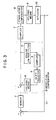
- Fig. 3 shows a block diagram of another embodiment.
- an internal connection of the repetition compensator 2 has been modified so that the analog low-pass filter 3, the sampler 4, the shift register 5 and the holding means 6 are connected in series.
- the output of the holding means 6 is added to the servo error to be inputted to the sampler 7.
- the shift register 5 sequentially stores the servo error signals at each sampling time which is set by the sampler 4. It also outputs the sampled values of one period earlier at each sampling time for the addition to the servo error signal to be inputted to the sampler 7 so that the periodic disturbance due to the eccentricity of the recording medium is suppressed.
- the sampling frequency of the repetition compensator 2 is again set lower than the sampling frequency of the digital stabilization compensator 8.
- the capacity of the shift register 5 can be reduced and the same effect as that in the previous embodiment is attained.
- Fig. 4 shows a characteristic chart of measurement of change in the servo error signal to the number of rotations (time) of the recording medium.
- Condition of the experiment are that the ratio f2/f1 of the sampling frequency f1 of the repetition compensator and the sampling frequency f2 of the digital stabilization compensator is 5, and the initial value of the shift register is all-zero.
- the servo error signal is substantially zero after the second rotation of the recording medium. This indicates that the laser spot and the target track are coincide and the laser spot well tracks the target track.
- the servo error signal is not zero at the first rotation of the recording medium after the pull-in of the servo error signal. This is due to the fact that the initial value of the shift register has been set to zero. Accordingly, a steady error of the rotation frequency and the frequency components which are multiples of the rotation frequency remains only in the first rotation of the recording medium but this does not raise any practical problem.
- the sampling frequency f1 of the repetition compensator is set to 1/5 of the sampling frequency f2 of the digital stabilization compensator so that the capacity of the shift register is reduced to 1/5
- the control system operates equally well as the control system having the ratio f2/f1 of 1.
- the sampling frequency of the repetition compensator is set lower than that of the digital stabilization compensator.
- the capacity of the shift register used in the repetition compensator can be effectively reduced without any affect to the control operation. Accordingly, the circuit configuration of the apparatus is simplified and the reduction of size and cost of the apparatus is attained.
- the present invention is applicable to not only the tracking servo control but also the focusing servo control and the servo control of a spindle motor which drives the recording medium.
Landscapes
- Physics & Mathematics (AREA)
- Optics & Photonics (AREA)
- Optical Recording Or Reproduction (AREA)
- Moving Of The Head To Find And Align With The Track (AREA)
- Moving Of The Head For Recording And Reproducing By Optical Means (AREA)
Applications Claiming Priority (2)
| Application Number | Priority Date | Filing Date | Title |
|---|---|---|---|
| JP33887/90 | 1990-02-16 | ||
| JP2033887A JP2593229B2 (ja) | 1990-02-16 | 1990-02-16 | 光ディスク装置 |
Publications (3)
| Publication Number | Publication Date |
|---|---|
| EP0442712A2 true EP0442712A2 (de) | 1991-08-21 |
| EP0442712A3 EP0442712A3 (en) | 1992-04-08 |
| EP0442712B1 EP0442712B1 (de) | 1996-05-22 |
Family
ID=12399037
Family Applications (1)
| Application Number | Title | Priority Date | Filing Date |
|---|---|---|---|
| EP91301139A Expired - Lifetime EP0442712B1 (de) | 1990-02-16 | 1991-02-13 | Optisches Informationsaufzeichnungs- und/oder Wiedergabegerät |
Country Status (3)
| Country | Link |
|---|---|
| EP (1) | EP0442712B1 (de) |
| JP (1) | JP2593229B2 (de) |
| DE (1) | DE69119621T2 (de) |
Family Cites Families (8)
| Publication number | Priority date | Publication date | Assignee | Title |
|---|---|---|---|---|
| JPS59191144A (ja) * | 1983-04-14 | 1984-10-30 | Sony Corp | 光ピツクアツプのトラツキングサ−ボ回路 |
| NL8303564A (nl) * | 1983-10-17 | 1985-05-17 | Philips Nv | Inrichting voor het weergeven van informatie van een optisch uitleesbare registratiedrager. |
| JPS61192971A (ja) * | 1985-02-21 | 1986-08-27 | Hamamatsu Gasket Seisakusho:Kk | 金属ガスケツト |
| JPH06103539B2 (ja) * | 1985-12-06 | 1994-12-14 | 株式会社日立製作所 | 光デイスクトラツキング装置 |
| US4949331A (en) * | 1985-06-19 | 1990-08-14 | Hitachi, Ltd. | Apparatus and record carrier for optical disc memory with correction pattern and master disc cutting apparatus |
| US4866688A (en) * | 1985-12-20 | 1989-09-12 | Hitachi, Ltd. | Composite tracking servo system for optical disc apparatus with track offset correction |
| DE3783114T2 (de) * | 1986-09-20 | 1993-04-22 | Pioneer Electronic Corp | Servomechanismus fuer eine aufzeichnungsplatte-wiedergabeanordnung. |
| JPS63160359U (de) * | 1987-11-20 | 1988-10-20 |
-
1990
- 1990-02-16 JP JP2033887A patent/JP2593229B2/ja not_active Expired - Fee Related
-
1991
- 1991-02-13 EP EP91301139A patent/EP0442712B1/de not_active Expired - Lifetime
- 1991-02-13 DE DE69119621T patent/DE69119621T2/de not_active Expired - Fee Related
Also Published As
| Publication number | Publication date |
|---|---|
| DE69119621D1 (de) | 1996-06-27 |
| JP2593229B2 (ja) | 1997-03-26 |
| EP0442712A3 (en) | 1992-04-08 |
| JPH03238675A (ja) | 1991-10-24 |
| DE69119621T2 (de) | 1996-09-26 |
| EP0442712B1 (de) | 1996-05-22 |
Similar Documents
| Publication | Publication Date | Title |
|---|---|---|
| EP0393001B1 (de) | Verfahren und Gerät zur Steuerung eines Plattengerätes | |
| KR940002001B1 (ko) | 액세스 방법과 그 정보 검색장치 | |
| US5479388A (en) | Servo control system for head recording and/or reproducing information on and/or from recording medium | |
| US4817069A (en) | Tracking control system of an optical pick-up | |
| US5029155A (en) | Optical information recording/reproducing apparatus in which recording power is set prior to recording | |
| US4835752A (en) | Device for driving and controlling optical head for use in optical disk system | |
| EP0325434B1 (de) | Spurzugangsregelsystem | |
| CA2244961C (en) | Closed loop servo operation for focus control | |
| US6266304B1 (en) | Disc eccentricity measuring apparatus and method thereof and apparatus for recording and/or reproducing disc-shaped recording medium | |
| US4956832A (en) | Tracking-deviation detector apparatus capable of preventing overwriting of data on an adjacent track | |
| EP0605239B1 (de) | Informationsaufzeichnungs- und wiedergabegerät | |
| US5671200A (en) | Method for detecting the movement of a light beam and optical information reproduction apparatus using the same | |
| US4918680A (en) | Focus-servo correction utilizing storage of detected focus errors | |
| US6392971B1 (en) | Focus control method and optical disc recording/reproducing apparatus | |
| US7327643B2 (en) | Radial tilt compensating optical disk apparatus using tracking control loop gain | |
| EP1385156B1 (de) | Verfahren und Gerät zur Korrektur der sphärischen Aberration | |
| US5247502A (en) | Optical information recording and/or reproducing apparatus and method for sampling an irradiation state error signal | |
| US5260923A (en) | Optical information processing apparatus in which an optical head is moved in accordance with a lens positional signal eliminating an eccentric component therefrom | |
| EP0442712A2 (de) | Optisches Informationsaufzeichnungs- und/oder Wiedergabegerät | |
| US5724329A (en) | Apparatus for controlling rotational servo by using frequency pulse signal generator | |
| US7304936B2 (en) | Method and apparatus for controlling power of laser diode in optical disc drive | |
| US6198085B1 (en) | Repeat control apparatus, information reproducing apparatus and information recording apparatus | |
| US5780982A (en) | Method of and apparatus for controlling rotation number of motor | |
| JP3978246B2 (ja) | 光ディスクトラッキング制御装置及び方法 | |
| US5172353A (en) | Track seeking control apparatus for use in data recording/reproduction systems having data tracks thereon |
Legal Events
| Date | Code | Title | Description |
|---|---|---|---|
| PUAI | Public reference made under article 153(3) epc to a published international application that has entered the european phase |
Free format text: ORIGINAL CODE: 0009012 |
|
| AK | Designated contracting states |
Kind code of ref document: A2 Designated state(s): DE FR GB IT NL |
|
| PUAL | Search report despatched |
Free format text: ORIGINAL CODE: 0009013 |
|
| AK | Designated contracting states |
Kind code of ref document: A3 Designated state(s): DE FR GB IT NL |
|
| 17P | Request for examination filed |
Effective date: 19920824 |
|
| 17Q | First examination report despatched |
Effective date: 19940727 |
|
| GRAH | Despatch of communication of intention to grant a patent |
Free format text: ORIGINAL CODE: EPIDOS IGRA |
|
| GRAA | (expected) grant |
Free format text: ORIGINAL CODE: 0009210 |
|
| AK | Designated contracting states |
Kind code of ref document: B1 Designated state(s): DE FR GB IT NL |
|
| REF | Corresponds to: |
Ref document number: 69119621 Country of ref document: DE Date of ref document: 19960627 |
|
| ET | Fr: translation filed | ||
| ITF | It: translation for a ep patent filed | ||
| PLBE | No opposition filed within time limit |
Free format text: ORIGINAL CODE: 0009261 |
|
| STAA | Information on the status of an ep patent application or granted ep patent |
Free format text: STATUS: NO OPPOSITION FILED WITHIN TIME LIMIT |
|
| 26N | No opposition filed | ||
| REG | Reference to a national code |
Ref country code: GB Ref legal event code: IF02 |
|
| PGFP | Annual fee paid to national office [announced via postgrant information from national office to epo] |
Ref country code: DE Payment date: 20090228 Year of fee payment: 19 Ref country code: NL Payment date: 20090217 Year of fee payment: 19 |
|
| PGFP | Annual fee paid to national office [announced via postgrant information from national office to epo] |
Ref country code: GB Payment date: 20090218 Year of fee payment: 19 |
|
| PGFP | Annual fee paid to national office [announced via postgrant information from national office to epo] |
Ref country code: IT Payment date: 20090205 Year of fee payment: 19 |
|
| PGFP | Annual fee paid to national office [announced via postgrant information from national office to epo] |
Ref country code: FR Payment date: 20090223 Year of fee payment: 19 |
|
| REG | Reference to a national code |
Ref country code: NL Ref legal event code: V1 Effective date: 20100901 |
|
| GBPC | Gb: european patent ceased through non-payment of renewal fee |
Effective date: 20100213 |
|
| REG | Reference to a national code |
Ref country code: FR Ref legal event code: ST Effective date: 20101029 |
|
| PG25 | Lapsed in a contracting state [announced via postgrant information from national office to epo] |
Ref country code: FR Free format text: LAPSE BECAUSE OF NON-PAYMENT OF DUE FEES Effective date: 20100301 Ref country code: NL Free format text: LAPSE BECAUSE OF NON-PAYMENT OF DUE FEES Effective date: 20100901 |
|
| PG25 | Lapsed in a contracting state [announced via postgrant information from national office to epo] |
Ref country code: DE Free format text: LAPSE BECAUSE OF NON-PAYMENT OF DUE FEES Effective date: 20100901 |
|
| PG25 | Lapsed in a contracting state [announced via postgrant information from national office to epo] |
Ref country code: IT Free format text: LAPSE BECAUSE OF NON-PAYMENT OF DUE FEES Effective date: 20100213 Ref country code: GB Free format text: LAPSE BECAUSE OF NON-PAYMENT OF DUE FEES Effective date: 20100213 |