EP0442721B1 - Strickschloss - Google Patents
Strickschloss Download PDFInfo
- Publication number
- EP0442721B1 EP0442721B1 EP91301162A EP91301162A EP0442721B1 EP 0442721 B1 EP0442721 B1 EP 0442721B1 EP 91301162 A EP91301162 A EP 91301162A EP 91301162 A EP91301162 A EP 91301162A EP 0442721 B1 EP0442721 B1 EP 0442721B1
- Authority
- EP
- European Patent Office
- Prior art keywords
- cam
- knitting
- needle
- butt
- knit
- Prior art date
- Legal status (The legal status is an assumption and is not a legal conclusion. Google has not performed a legal analysis and makes no representation as to the accuracy of the status listed.)
- Expired - Lifetime
Links
Images


Classifications
-
- D—TEXTILES; PAPER
- D04—BRAIDING; LACE-MAKING; KNITTING; TRIMMINGS; NON-WOVEN FABRICS
- D04B—KNITTING
- D04B15/00—Details of, or auxiliary devices incorporated in, weft knitting machines, restricted to machines of this kind
- D04B15/32—Cam systems or assemblies for operating knitting instruments
- D04B15/36—Cam systems or assemblies for operating knitting instruments for flat-bed knitting machines
- D04B15/362—Cam systems or assemblies for operating knitting instruments for flat-bed knitting machines with two needle beds in V-formation
- D04B15/365—Cam systems or assemblies for operating knitting instruments for flat-bed knitting machines with two needle beds in V-formation with provision for loop transfer from one needle bed to the other
-
- D—TEXTILES; PAPER
- D04—BRAIDING; LACE-MAKING; KNITTING; TRIMMINGS; NON-WOVEN FABRICS
- D04B—KNITTING
- D04B15/00—Details of, or auxiliary devices incorporated in, weft knitting machines, restricted to machines of this kind
- D04B15/66—Devices for determining or controlling patterns ; Program-control arrangements
- D04B15/82—Devices for determining or controlling patterns ; Program-control arrangements characterised by the needle cams used
Definitions
- the present invention relates to a knit run cam system for moving a needle vertically when fabrics are knitted.
- a needle for knitting fabrics which is moved up and down by placing a needle butt projecting from the needle in contact with a cam for vertically moving a needle provided on a carriage, and vertically moving the needle as the carriage moves.
- a needle having only one butt a needle not having been lowered by a knitting cam for lowering the needle is lowered by a further succeeding guide cam, and therefore the number of needles required by the carriage increases, and as a result the load increases.
- DE-A-1560902 there is described a knit run cam system comprising two cams.
- the needle butt is raised to the uppermost position by the cam 10
- the needle is lowered by the cam 16
- the needle butt is further lowered by the cam 11, if the carriage is moved to the right.
- both the needles for processing the knit stitches and the needles for processing the tack stitches are lowered to the same position, with the result that the lowering distance of the needle butt for the tack stitch cannot be decreased.
- both sets of needles are lowered by the same stitch cams 11, 12. Therefore, the size of the knitting loops of the knit stitches and of the tack stitches cannot be selectively changed.
- both the needles for processing the knit stitches and the needles for processing the tack stitches are lowered to the same position and the loop size of the stitches cannot be changed.
- FR-A-606887 shows a construction for determining whether loops are to be formed or not in the next course. Knitting loops having different sizes cannot be formed.
- a knit run cam system comprising:
- the knitting needle is moved upwards to a knitting position by a lifting cam, and, after the feed of yarn, the needle is lowered to the lowermost position by the knitting cam.
- the tack needle is disengaged from the knitting cam, when it is lowered from the tack position, without being lowered to the lowermost position by the knitting cam, and is lowered by the knitting cam and by a lowering cam having a needle butt lowering inclined surface which overlaps in a range of at least a part in the same phase of a cam plate in a moving direction of the carriage.
- Fig. 1 shows the position where a cam lock 1 of a carriage is viewed from the underside.
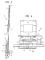
- Fig. 2 is a side view of a needle 2, a select jack 3, a selector 4, a select jack presser 5 and other components placed at positions corresponding in alignment to the cam lock 1.
- the needle 2 used in the knitting apparatus according to the present invention comprises a compound needle which is designed so that a slider 7 is slidably inserted into an upper portion of the needle at the extreme end of a needle body 6, and a slider butt 8 can be actuated so that a hook 9 of the needle body 6 can be opened and closed by the slider 7.
- Reference numeral 10 designates a needle butt provided on the needle body 6.
- a select jack butt 11 is provided at its base with recesses 12, 13 and 14. Each of the recesses 12, 13 and 14 is engageable with a wire 15 provided through a needle bed (not shown) to define positions of the select jack butt 11.
- the select jack butt 11 assumes a welt position when the wire 15 engages recess 12, assumes a tack position when engaging recess 13 and assumes a knit position when engaging recess 14.
- the select jack presser 5 comprises a ]-shaped elastic plate which is designed so that the upper edge thereof is brought into a web 16 inserted through a needle bed (not shown) to press against the select jack 3 at the end thereof and urge the select jack butt 11 in an upward direction.
- Reference numeral 17 designates a selector butt of the selector 4.
- the cam lock 1 comprises a knitting lock 22 and a transfer lock 23 provided on a cam plate 21.
- the knitting lock 22 comprises a lifting cam 24 of generally trapezoidal shape, with two inclined surfaces which serve as lifting cam surfaces 24a and 24b; a trapezoidal centre cam 25 having an angle-recess cam 25a provided on the same centre line as the lifting cam 24; left and right knitting cams 26A and 26B which are slidably provided in a / ⁇ -shape on respective sides of the centre cam 25; a crescent-shaped slider guide cam 27 provided at an upper level of the centre cam 25; and slider guide cams 29A and 29B provided on each side of the slider guide cam 27 to guide the butt 8 of the slider 7, along with a guide cam 28, moved upwards by the slider cam 27.
- the transfer lock 23 comprises a trapezoidal stitch transfer lifting cam 30 positioned near the top of the trapezoidal lifting cam 24 and having a height sufficient to move the needle 2 up to a stitch transfer position; a stitch receiving needle lifting cam 33 slidably provided within a depression 32 formed with an inclined frictional surface 31 in the central portion of the lifting cam 24; and the centre cam 25 which also comprises a part of the knitting lock 22.
- Reference numeral 34 denotes a fixed guide cam.
- the knitting cams 26A and 26B are symmetrically supported on the lifting cam surfaces 24a and 24b of the lifting cam 24 so that the cams may be slidably moved up and down with respect to the cam plate 21.
- the knitting cam 26B has a surface facing the lifting cam surface 24b of the lifting cam 24, said surface serving as a loop-forming lowering cam surface 26a.
- a central portion of the cam 26B comprises a recess 41, which constitutes a bevel 42 from a portion positioned slightly inwardly of the loop-forming lowering cam surface 26a towards the recess 41.
- the lower end following the lowering cam surface 26a is formed with a shoulder 43 having a height at which the butt at a half-height position can pass through, and the needle having the butt at the half-height position is lowered to the shoulder.
- the needle having a butt at the full-height position is lowered to the lowermost end 44 so that fabrics whose density varies can be knitted.
- An extending portion 45 extending into the recess 41 of the knitting cam 26B is provided on the fixed guide cam 34.
- the extending portion 45 has one side which serves as a lowering cam surface 45a for tack, said lowering cam surface 45a being parallel with the loop-forming lowering cam surface 26a of the knitting cam 26B.
- the elevating means is symmetrically formed. Therefore, a stitch cam control device 50 of the knitting cam 26B will be described hereinafter.
- the cam plate 21 is formed with a slot 51 for obliquely upwardly moving the knitting cam 26B, a sliding member 52 being slidably fitted in the slot 51.
- the knitting cam 26B and a keeper member 53 are fixed integrally with the sliding member 52, to the lower surface and to the upper surface of the sliding member 52 respectively.
- a stitch cam control motor 56 is mounted through a motor mounting plate 55 on an inverted ]-shaped base bed 54 provided on the upper surface of the cam plate 21.
- a stitch cam control cam 59 having a spiral cam groove 58 is mounted on a motor shaft 57 of the stitch cam control motor 56.
- a cam follower 61 provided on a stitch cam control lever 60 is fitted into the cam groove 58.
- the stitch cam control lever 60 is pivotally supported on a shaft 63 within a recess 62 of the base bed 54.
- the cam follower 61 is supported on the central portion thereof and a holding lever 64 is supported by a shaft 65.
- the extreme end of the holding lever 64 comes into contact with a bent portion 66 at the extreme end of the stitch cam control lever 60, and a cam follower 67 supported on the upper surface of the keeper member 53 is.held by the holding lever 64 and the stitch cam control lever 60.
- a spring 68 is provided between the other end of the holding lever 64 and the stitch cam control lever 60 so that the holding lever 64 and the bent portion 66 at the extreme end of the stitch cam control lever 60 are always in contact with each other to constitute a shock absorbing mechanism.
- Reference numeral 69 designates a proximity sensor for detecting a zero position of the stitch cam control cam 59 so that when a projecting portion 70 of the stitch cam control cam 59 comes near, the sensor detects that projection and knows the zero position to stop the stitch cam control motor 56.
- the zero position is that where the cam follower 61 being fitted in the cam groove 58 of the stitch cam control cam 59 is at the centre of the cam 59, that is, the position close to the motor shaft 57, and the projecting portion 70 of the stitch cam control cam 59 is close to the proximity sensor 69.
- the knitting cam 26A is in the uppermost position
- the stitch cam control device 50 is as shown in Fig. 3 so that conversely the knitting cam 26B is in the lowermost position.
- the needle butt 10 contacts the lowering cam surface 25b of the centre cam 25 and the lowering cam surface 26a of the knitting cam 26B and moves down, but the slider butt 8 is held between the guide cam 28 and the slider guide cam 29B and moves substantially horizontally, during which time the needle 2 moves down while the end of the slider 7 does not move down. Therefore, the end of the slider comes closer to the hook 9 to close the hook 9.
- the needle butt 10 of the needle 2 lowered by the lowering cam surface 26a of the knitting cam 26B is at a full height since the presser 35B goes down, so that the select jack butt 10 is not pressed.
- the needle butt 10 is lowered to the lowermost end 44 of the knitting cam to pull the yarn previously fed and to produce fabrics having the standard density.
- the presser 35B When the needle butt 10 is lowered by the lowering cam surface 26a of the knitting cam 26B, the presser 35B is actuated to force the select jack butt 11 into the half-height position and to set the needle butt 10 of the needle 2 to the half-height position through the select jack 3.
- the needle butt 10 of the needle 2 which has received the yarn and has been moved down along the lowering cam surface 26a of the knitting cam 26 arrives near the lowermost end 44 of the knitting cam 26B.
- the needle butt 10 passes through the shoulder 43 at the half-height position so that the amount the needle 2 is lowered becomes less than that at the time of knitting ordinary stitches. Therefore, stitches knitted by the needle 2 are somewhat small. Whether the standard stitches or small stitches are chosen according to the passage through the lowermost end 44 or the shoulder 43 of the knitting cam 26B, it is to be noted that the knitting cam 26 itself may be moved up and down in the following manner.
- the stitch cam control device 50 of the knitting cam 26B in which the stitch cam control cam 59 has moved up to the uppermost position until termination of the knitting in the previous course and has rotated to the position at which the projecting portion 70 is opposite the proximity sensor 69 should cause the knitting cam 26B to be lowered to a predetermined density position.
- the angle of rotation of the knitting cam control motor 56 determines the lowering position by suitably inputting the number of pulses during the rotation of the motor according to the position thereof.
- the knitting cam control cam 59 which has most rotated in the stitch cam control device 50 shown in Fig.
- the select jack butt 11 is set to the position II.
- the select butt 11 of the selector 4 and the needle butt 10 of the needle 2 move along the lines II and II′ respectively.
- the pressers 36A and 36B go down, whereas the presser 37 projects.
- the needle butt 10 comes into contact with and moves along the lifting cam surface 24a of the lifting cam 24, but when the needle butt 10 reaches the portion 24b of the shoulder of the lifting cam 24, the select jack butt 11 is pushed in by the projecting presser 37 and therefore the needle butt 10 does not come to the top of the lifting cam 24 and moves crossing thereover.
- the slider butt 8 moves horizontally until it passes through the straight line edge 29a of the slider guide cam 29A similarly to the needle which moves up to the aforesaid knit position. Therefore, the hook 9 is moved away from the extreme end of the slider 7 due to the upward movement of the needle butt 10 of the needle body 6, thereby to open the hook 9.
- the needle butt 10 does not come to the top of the lifting cam but moves crossing thereover as mentioned above, and therefore the slider butt 8 is also not moved upwards any further but passes through under the slider guide cam 27 while the hook 9 remains opened, and is lowered by the lowering cam surface 29b of the slider guide cam 29B, after which the slider butt 8 moves horizontally.
- the needle butt 10 which has crossed the top of the lifting cam 24 moves down along the lowering inclined surface 25b of the centre cam 25 and the lowering inclined surface 26a of the knitting cam 26 and runs taking the same course as the needle 2 which has moved up to the knit position and been lowered to the lowermost end of the knitting cam 26 to knit tack stitches having the standard density.
- the needle butt 10 When the select jack butt 11 is released from being pressed by the presser 36B, the needle butt 10 again projects and enters the course 46 between the knitting cam 26 and the projecting portion 45 of the fixed guide cam 34 and comes into contact with the lowering inclined surface 45a of the fixed guide cam 34 so that the needle butt 10 is lowered to the lowermost end.
- the slider butt 8 passes horizontally along the lower edge of the straight line edge 29a of the slider guide cam 29B to feed a yarn to the hook 9, but the needle butt 10 comes into contact with the lowering inclined surface 45a of the fixed guide cam 34 so that the hook 9, due to the lowering of the needle body 6 and due to the movement of the slider butt 8 towards the extreme end, is closed during the movement to the lowermost end.
- the slider 7 moves along the line II′ without reckless movement due to the friction between the slider side and the needle groove wall.
- the knitting yarn to be fed is pulled to form a loop when the needle butt 10 moves down along the lowering guide surface 45a of the projecting portion 45 of the fixed guide cam 34. Since the position of the lowermost position of the projecting portion 45 of the fixed guide cam 34 is higher than the lowermost end 44 of the knitting cam 26B, the pull-in amount of the yarn is less than that and, accordingly, tack stitches which are small in density are knitted.
- the select jack butt 11 When the welt position in which the needle 2 is not moved upwards at all is employed, the select jack butt 11 is set to the position III of the presser 38. When the presser 38 is projected to move the carriage, the select jack butt 11 is forced in by the presser 38 and accordingly the needle butt 10 also goes into the needle groove, as a consequence of which the needle butt 11 and the slider butt 8 do not come into contact with any cam of the cam lock 1 but they pass through the positions III′ and III ⁇ respectively, and the needle 2 fails to act at all.
- position I is the knit position
- position II is the tack position
- position III is the welt position
- the needle can be raised to the knit position unless the presser 37 is activated, and when knit stitches having the standard size and knit stitches which are smaller than standard are prepared, the knit stitches of the standard size and the knit stitches smaller than standard select needles at the position II and position I respectively, so that the presser 35B acts similarly to that as described previously to cause it to pass through the shoulder 43 of the knitting cam 26.
- knit stitches and tack stitches of standard size and knit stitches and tack stitches of smaller than the standard size can be knitted by suitably selecting the needles.
- the cam for lowering knitting needles different in the yarn lowering amount and the cam for lowering the tack needle can overlap the range for lowering the respective needles in the knitting width direction, and therefore the range of the provision of the stitch presser bar that has to be provided in the range in which the needle for knitting fabrics lowers to the resting position can be decreased, thereby to eliminate that cause of trouble.
- the needle lowering number can be decreased, and therefore the load when the needle is lowered can be reduced. Furthermore, since the cam for knitting tack stitches can easily shorten the yarn lowering length (density) as compared with the length for the knitting cam, the tack stitches can be made dense, and if this apparatus is utilised for a portion in the state where a loop is formed in the boundary of patterns of pattern fabrics or the like, fabrics in which the boundary of patterns is dense can also be obtained.
Landscapes
- Engineering & Computer Science (AREA)
- Textile Engineering (AREA)
- Knitting Machines (AREA)
- Treatment Of Fiber Materials (AREA)
- Preliminary Treatment Of Fibers (AREA)
Claims (4)
- Strickschloss-System enthaltend:eine Stricknadel (2) mit einem Nadelfuß (10),ein Strickschlossteil (26B) mit einer schiefen Oberfläche zum Absenken des Nadelfußes (26a) und einem untersten Ende (44), wobei der Nadelfuß (10) der Stricknadel mit der schiefen Oberfläche zum Absenken des Nadelfußes (26a) und dem untersten Ende (44) in Eingriff kommt, um Strick- und Umkehrmaschen zu bilden, und wobei das Strickschlossteil (26B) eine Ausnehmung (41) hat, und ein befestigtes Führungsschlossteil (34) mit einer schiefen Oberfläche zum Absenken des Nadelfußes (45a) und eine unterste Endverlängerung (45) für den Eingriff mit dem Nadelfuß (10) der Stricknadel, um Umkehrmaschen einer verringerten Dichte zu bilden, wobei die schiefe Oberfläche zum Absenken des Nadelfußes (45a) und die unterste Endverlängerung (45) des befestigten Führungsschlossteils die Ausnehmung (41) in dem Strickschlossteil (26B) so überlappen, daß die unterste Endverlängerung (45) des befestigten Führungs-schlossteils (34) von dem untersten Ende (44) des Strickschlossteils (26B) beabstandet ist.
- Strickschloss-System nach Anspruch 1, dadurch gekennzeichnet, daß das unterste Ende (44) des Strickschlossteils (26B) einen Stufenabschnitt (43) zum Eingriff mit dem Nadelfuß (10) hat, um Strickmaschen einer verringerten Dichte zu bilden.
- Strickschloss-System nach Anspruch 1 oder 2, dadurch gekennzeichnet, daß die Ausnehmung (41) an einem mittleren Abschnitt des Strickschlossteils (26B) gebildet ist.
- Strickschloss-System nach Anspruch 1, 2 oder 3, weiterhin gekennzeichnet durch:eine Schlossplatte (21) mit einem schiefen Schlitz (51) darin,eine Maschenschloss-Steuerung mit einem verschiebbaren Teil (52), der verschiebbar in den Schlitz (51) in der Schlossplatte (21) eingesetzt ist und mit dem Strickschlossteil (26B) verbunden ist, um den Strickschlossteil (26B) schief auf der Schlossplatte (21) zu bewegen,einen Maschenschloss-Steuerungsmotor (56) mit einer Motorwelle (57), die auf der oberen Oberfläche der Schlossplatte (21) angebracht ist,einen Maschenschloss-Steuerungsschlossteil (59) mit einem spiralförmigen Schlosskanal (58), der an der Motorwelle (57) angebracht ist,ein erstes Gleitstück (61), das einen Maschenschloss-Steuerungshebel (60) umfaßt, der in dem spriralförmigen Schlosskanal (58) aufgenommen ist,ein zweites Gleitstück (67) undeine Einrichtung (64), um den Maschenschloss-Steuerungshebel (60) mit dem verschiebbaren Teil (52) durch das zweite Gleitstück (67) in Eingriff zu bringen.
Applications Claiming Priority (2)
| Application Number | Priority Date | Filing Date | Title |
|---|---|---|---|
| JP2033327A JP2610533B2 (ja) | 1990-02-14 | 1990-02-14 | ニット,トランスファー兼用カム |
| JP33327/90 | 1990-02-14 |
Publications (3)
| Publication Number | Publication Date |
|---|---|
| EP0442721A2 EP0442721A2 (de) | 1991-08-21 |
| EP0442721A3 EP0442721A3 (en) | 1992-11-25 |
| EP0442721B1 true EP0442721B1 (de) | 1996-01-03 |
Family
ID=12383462
Family Applications (1)
| Application Number | Title | Priority Date | Filing Date |
|---|---|---|---|
| EP91301162A Expired - Lifetime EP0442721B1 (de) | 1990-02-14 | 1991-02-13 | Strickschloss |
Country Status (6)
| Country | Link |
|---|---|
| US (1) | US5251462A (de) |
| EP (1) | EP0442721B1 (de) |
| JP (1) | JP2610533B2 (de) |
| KR (1) | KR920010355B1 (de) |
| DE (1) | DE69115948T2 (de) |
| ES (1) | ES2084097T3 (de) |
Cited By (1)
| Publication number | Priority date | Publication date | Assignee | Title |
|---|---|---|---|---|
| CN101956289A (zh) * | 2010-09-25 | 2011-01-26 | 茅木泉 | 一种电脑编织横机的密度调节装置 |
Families Citing this family (11)
| Publication number | Priority date | Publication date | Assignee | Title |
|---|---|---|---|---|
| US5694792A (en) * | 1995-06-15 | 1997-12-09 | Shima Seiki Manufacturing, Ltd. | Needle selection device of flat knitting machine |
| DE19924333A1 (de) * | 1999-05-27 | 2000-11-30 | Stoll & Co H | Verstellvorrichtung für Schlossteile von Flachstrickmaschinen |
| JP3899315B2 (ja) * | 2001-01-30 | 2007-03-28 | 株式会社島精機製作所 | 横編機における度目制御装置 |
| KR100979440B1 (ko) * | 2002-06-26 | 2010-09-02 | 가부시키가이샤 시마세이키 세이사쿠쇼 | 횡편기의 니들 실렉션 장치 |
| CN100400732C (zh) * | 2002-08-06 | 2008-07-09 | 株式会社岛精机制作所 | 具有可调密度变化机构的织机 |
| WO2009031315A1 (ja) * | 2007-09-05 | 2009-03-12 | Shima Seiki Mfg., Ltd. | 横編機 |
| JP5757830B2 (ja) * | 2011-09-13 | 2015-08-05 | 株式会社島精機製作所 | 複合針を備える横編機、および横編機のスライダー制御方法 |
| JP2013067465A (ja) * | 2011-09-21 | 2013-04-18 | Murata Machinery Ltd | 糸処理装置及び糸巻取装置 |
| CN102493122B (zh) * | 2011-12-22 | 2013-07-24 | 飞虎科技有限公司 | 电脑横机的机头度目调平装置及方法 |
| CN105734815B (zh) * | 2016-03-18 | 2018-07-13 | 桐乡市强隆机械有限公司 | 具有联动控制机构的横机底板 |
| IT201900009216A1 (it) * | 2019-06-17 | 2020-12-17 | Santoni & C Spa | Macchina tessile circolare con sistema di sfasamento della camma maglia del piatto degli aghi |
Family Cites Families (10)
| Publication number | Priority date | Publication date | Assignee | Title |
|---|---|---|---|---|
| BE366267A (de) * | ||||
| FR606887A (fr) * | 1925-11-26 | 1926-06-22 | Appareil destiné aux métiers de bonneterie rectilignes pour l'obtention de tricots à dessin | |
| DE1560902A1 (de) * | 1961-10-10 | 1969-08-28 | Aquila Spa | Schlitten fuer von Hand oder motorisch zu betreibende Flachstrickmaschinen |
| GB2095706B (en) * | 1980-09-30 | 1984-05-16 | Shima Idea Center Co Ltd | Weft knitting machine capable of altering wale density |
| JPS591750A (ja) * | 1982-04-28 | 1984-01-07 | 株式会社島アイデア・センタ− | 横編機 |
| DE3310671C2 (de) * | 1983-03-24 | 1986-04-17 | H. Stoll Gmbh & Co, 7410 Reutlingen | Verfahren und Einrichtung zur Einstellung der Abzugsteile eines Strickschlosses |
| US4510755A (en) * | 1983-08-10 | 1985-04-16 | Transamerica Delaval Inc. | Demineralization of feed water in a steam system |
| DE3433628C2 (de) * | 1984-09-13 | 1986-12-18 | H. Stoll Gmbh & Co, 7410 Reutlingen | Schloßsystem für Flachstrickmaschinen und Verfahren zum kombinierten Bilden und Umhängen von Maschen an Flachstrickmaschinen |
| DE3537612C2 (de) * | 1985-10-23 | 1994-07-28 | Stoll & Co H | Schloßsystem für Flachstrickmaschinen |
| CH671977A5 (de) * | 1986-12-01 | 1989-10-13 | Dubied & Cie Sa E |
-
1990
- 1990-02-14 JP JP2033327A patent/JP2610533B2/ja not_active Expired - Fee Related
-
1991
- 1991-02-07 US US07/651,965 patent/US5251462A/en not_active Expired - Lifetime
- 1991-02-13 ES ES91301162T patent/ES2084097T3/es not_active Expired - Lifetime
- 1991-02-13 KR KR1019910002504A patent/KR920010355B1/ko not_active Expired
- 1991-02-13 DE DE69115948T patent/DE69115948T2/de not_active Expired - Lifetime
- 1991-02-13 EP EP91301162A patent/EP0442721B1/de not_active Expired - Lifetime
Cited By (1)
| Publication number | Priority date | Publication date | Assignee | Title |
|---|---|---|---|---|
| CN101956289A (zh) * | 2010-09-25 | 2011-01-26 | 茅木泉 | 一种电脑编织横机的密度调节装置 |
Also Published As
| Publication number | Publication date |
|---|---|
| US5251462A (en) | 1993-10-12 |
| EP0442721A3 (en) | 1992-11-25 |
| KR920010355B1 (ko) | 1992-11-27 |
| DE69115948D1 (de) | 1996-02-15 |
| ES2084097T3 (es) | 1996-05-01 |
| JPH03241047A (ja) | 1991-10-28 |
| EP0442721A2 (de) | 1991-08-21 |
| DE69115948T2 (de) | 1996-09-05 |
| JP2610533B2 (ja) | 1997-05-14 |
| KR910015739A (ko) | 1991-09-30 |
Similar Documents
| Publication | Publication Date | Title |
|---|---|---|
| EP0442721B1 (de) | Strickschloss | |
| US6079231A (en) | Stitch loop holding apparatus for a flat knitting machine | |
| EP0060888B1 (de) | Schuss-strickmaschine mit veränderlicher stricklänge | |
| US5305619A (en) | Stitch increasing method and cams for flat knitting machine having stitch increasing function | |
| EP0567282B1 (de) | Flachstrickmachine und Verfahren zum Steuern der Schwingplatinen der Flachstrickmachine | |
| EP0751248A1 (de) | Strick- und Umhängeschlossteil für Flachstrickmaschine | |
| US5305620A (en) | Flat knitting machine | |
| EP0042838B1 (de) | Flachbett-strickmaschine und überführungssysteme dafür | |
| EP0698679B1 (de) | Strickschlussteil und Schluss | |
| US4141228A (en) | Pattern mechanism for a flat bed knitting machine | |
| JPH0684583B2 (ja) | 増目方法及び増目機能を有する横編機用操針カム | |
| TW548358B (en) | Weft knitting machine with transfer mechanism and transferring method | |
| US4463577A (en) | Flat knitting machine having a presser foot device | |
| JPH01104863A (ja) | ニツトランカム | |
| US5501085A (en) | Fabric holding-down mechanism for double knit machines | |
| TW584684B (en) | Weft knitting machine with transfer mechanism | |
| US3103110A (en) | Two-bed hand-knitting apparatus | |
| US3250093A (en) | Hand knitting machine | |
| JPH02251645A (ja) | 横編機における度目制御装置 | |
| US1718295A (en) | Knitting machine | |
| JP2530242B2 (ja) | 増目機能を有する横編機用操針カム | |
| KR0137290Y1 (ko) | 원형편물의 자카드기구 | |
| US3942339A (en) | Carriage for hand knitting machines having integral Jacquard cam pattern changing means | |
| JPH0325535B2 (de) | ||
| JPH05125644A (ja) | 横編機における目移し時の編針制御装置 |
Legal Events
| Date | Code | Title | Description |
|---|---|---|---|
| PUAI | Public reference made under article 153(3) epc to a published international application that has entered the european phase |
Free format text: ORIGINAL CODE: 0009012 |
|
| AK | Designated contracting states |
Kind code of ref document: A2 Designated state(s): CH DE ES FR GB IT LI |
|
| PUAL | Search report despatched |
Free format text: ORIGINAL CODE: 0009013 |
|
| AK | Designated contracting states |
Kind code of ref document: A3 Designated state(s): CH DE ES FR GB IT LI |
|
| 17P | Request for examination filed |
Effective date: 19930108 |
|
| 17Q | First examination report despatched |
Effective date: 19941115 |
|
| GRAA | (expected) grant |
Free format text: ORIGINAL CODE: 0009210 |
|
| AK | Designated contracting states |
Kind code of ref document: B1 Designated state(s): CH DE ES FR GB IT LI |
|
| PG25 | Lapsed in a contracting state [announced via postgrant information from national office to epo] |
Ref country code: LI Free format text: LAPSE BECAUSE OF FAILURE TO SUBMIT A TRANSLATION OF THE DESCRIPTION OR TO PAY THE FEE WITHIN THE PRESCRIBED TIME-LIMIT Effective date: 19960103 Ref country code: CH Free format text: LAPSE BECAUSE OF FAILURE TO SUBMIT A TRANSLATION OF THE DESCRIPTION OR TO PAY THE FEE WITHIN THE PRESCRIBED TIME-LIMIT Effective date: 19960103 |
|
| ITF | It: translation for a ep patent filed | ||
| REF | Corresponds to: |
Ref document number: 69115948 Country of ref document: DE Date of ref document: 19960215 |
|
| ET | Fr: translation filed | ||
| REG | Reference to a national code |
Ref country code: ES Ref legal event code: FG2A Ref document number: 2084097 Country of ref document: ES Kind code of ref document: T3 |
|
| REG | Reference to a national code |
Ref country code: CH Ref legal event code: PL |
|
| PLBE | No opposition filed within time limit |
Free format text: ORIGINAL CODE: 0009261 |
|
| STAA | Information on the status of an ep patent application or granted ep patent |
Free format text: STATUS: NO OPPOSITION FILED WITHIN TIME LIMIT |
|
| 26N | No opposition filed | ||
| REG | Reference to a national code |
Ref country code: GB Ref legal event code: IF02 |
|
| PGFP | Annual fee paid to national office [announced via postgrant information from national office to epo] |
Ref country code: ES Payment date: 20080324 Year of fee payment: 18 |
|
| PGFP | Annual fee paid to national office [announced via postgrant information from national office to epo] |
Ref country code: GB Payment date: 20080213 Year of fee payment: 18 |
|
| PGFP | Annual fee paid to national office [announced via postgrant information from national office to epo] |
Ref country code: FR Payment date: 20080208 Year of fee payment: 18 |
|
| GBPC | Gb: european patent ceased through non-payment of renewal fee |
Effective date: 20090213 |
|
| REG | Reference to a national code |
Ref country code: FR Ref legal event code: ST Effective date: 20091030 |
|
| REG | Reference to a national code |
Ref country code: ES Ref legal event code: FD2A Effective date: 20090214 |
|
| PG25 | Lapsed in a contracting state [announced via postgrant information from national office to epo] |
Ref country code: FR Free format text: LAPSE BECAUSE OF NON-PAYMENT OF DUE FEES Effective date: 20090302 Ref country code: GB Free format text: LAPSE BECAUSE OF NON-PAYMENT OF DUE FEES Effective date: 20090213 |
|
| PGFP | Annual fee paid to national office [announced via postgrant information from national office to epo] |
Ref country code: IT Payment date: 20100218 Year of fee payment: 20 |
|
| PGFP | Annual fee paid to national office [announced via postgrant information from national office to epo] |
Ref country code: DE Payment date: 20100226 Year of fee payment: 20 |
|
| PG25 | Lapsed in a contracting state [announced via postgrant information from national office to epo] |
Ref country code: ES Free format text: LAPSE BECAUSE OF NON-PAYMENT OF DUE FEES Effective date: 20090214 |
|
| REG | Reference to a national code |
Ref country code: DE Ref legal event code: R071 Ref document number: 69115948 Country of ref document: DE |
|
| PG25 | Lapsed in a contracting state [announced via postgrant information from national office to epo] |
Ref country code: DE Free format text: LAPSE BECAUSE OF EXPIRATION OF PROTECTION Effective date: 20110213 |