EP0442740B1 - Solid oxide fuel cells - Google Patents
Solid oxide fuel cells Download PDFInfo
- Publication number
- EP0442740B1 EP0442740B1 EP91301208A EP91301208A EP0442740B1 EP 0442740 B1 EP0442740 B1 EP 0442740B1 EP 91301208 A EP91301208 A EP 91301208A EP 91301208 A EP91301208 A EP 91301208A EP 0442740 B1 EP0442740 B1 EP 0442740B1
- Authority
- EP
- European Patent Office
- Prior art keywords
- gas feed
- feed pipe
- fuel cell
- support tube
- oxidizing gas
- Prior art date
- Legal status (The legal status is an assumption and is not a legal conclusion. Google has not performed a legal analysis and makes no representation as to the accuracy of the status listed.)
- Expired - Lifetime
Links
- 239000000446 fuel Substances 0.000 title claims description 95
- 239000007787 solid Substances 0.000 title claims description 21
- 239000007789 gas Substances 0.000 claims description 171
- 230000001590 oxidative effect Effects 0.000 claims description 127
- 239000007784 solid electrolyte Substances 0.000 claims description 15
- 239000002737 fuel gas Substances 0.000 claims description 14
- 230000002093 peripheral effect Effects 0.000 claims description 12
- 239000011148 porous material Substances 0.000 claims description 4
- 210000004027 cell Anatomy 0.000 description 48
- 239000001301 oxygen Substances 0.000 description 36
- 229910052760 oxygen Inorganic materials 0.000 description 36
- QVGXLLKOCUKJST-UHFFFAOYSA-N atomic oxygen Chemical compound [O] QVGXLLKOCUKJST-UHFFFAOYSA-N 0.000 description 25
- 238000006243 chemical reaction Methods 0.000 description 24
- VNWKTOKETHGBQD-UHFFFAOYSA-N methane Chemical compound C VNWKTOKETHGBQD-UHFFFAOYSA-N 0.000 description 15
- 238000010248 power generation Methods 0.000 description 14
- -1 oxygen ions Chemical class 0.000 description 11
- 230000009257 reactivity Effects 0.000 description 7
- 229910002328 LaMnO3 Inorganic materials 0.000 description 6
- MCMNRKCIXSYSNV-UHFFFAOYSA-N ZrO2 Inorganic materials O=[Zr]=O MCMNRKCIXSYSNV-UHFFFAOYSA-N 0.000 description 6
- 239000011195 cermet Substances 0.000 description 6
- 230000035882 stress Effects 0.000 description 6
- 230000007423 decrease Effects 0.000 description 5
- 230000000694 effects Effects 0.000 description 5
- 230000000149 penetrating effect Effects 0.000 description 5
- 230000036647 reaction Effects 0.000 description 5
- 230000003247 decreasing effect Effects 0.000 description 4
- 238000010304 firing Methods 0.000 description 4
- 229910002969 CaMnO3 Inorganic materials 0.000 description 3
- 229910002254 LaCoO3 Inorganic materials 0.000 description 3
- 229910002262 LaCrO3 Inorganic materials 0.000 description 3
- 229910002340 LaNiO3 Inorganic materials 0.000 description 3
- OKKJLVBELUTLKV-UHFFFAOYSA-N Methanol Chemical compound OC OKKJLVBELUTLKV-UHFFFAOYSA-N 0.000 description 3
- 230000002035 prolonged effect Effects 0.000 description 3
- 229910052712 strontium Inorganic materials 0.000 description 3
- CIOAGBVUUVVLOB-UHFFFAOYSA-N strontium atom Chemical compound [Sr] CIOAGBVUUVVLOB-UHFFFAOYSA-N 0.000 description 3
- 238000013459 approach Methods 0.000 description 2
- 210000005056 cell body Anatomy 0.000 description 2
- 238000010276 construction Methods 0.000 description 2
- 230000001419 dependent effect Effects 0.000 description 2
- 230000003292 diminished effect Effects 0.000 description 2
- 238000003487 electrochemical reaction Methods 0.000 description 2
- 238000003411 electrode reaction Methods 0.000 description 2
- 230000006872 improvement Effects 0.000 description 2
- 239000004615 ingredient Substances 0.000 description 2
- 238000005259 measurement Methods 0.000 description 2
- 238000000034 method Methods 0.000 description 2
- 230000035699 permeability Effects 0.000 description 2
- BASFCYQUMIYNBI-UHFFFAOYSA-N platinum Chemical compound [Pt] BASFCYQUMIYNBI-UHFFFAOYSA-N 0.000 description 2
- 230000000630 rising effect Effects 0.000 description 2
- 229910002076 stabilized zirconia Inorganic materials 0.000 description 2
- 238000003756 stirring Methods 0.000 description 2
- 241000220317 Rosa Species 0.000 description 1
- 230000015572 biosynthetic process Effects 0.000 description 1
- 239000003054 catalyst Substances 0.000 description 1
- 239000000919 ceramic Substances 0.000 description 1
- 239000003245 coal Substances 0.000 description 1
- 238000002485 combustion reaction Methods 0.000 description 1
- 239000000470 constituent Substances 0.000 description 1
- 238000001816 cooling Methods 0.000 description 1
- RKTYLMNFRDHKIL-UHFFFAOYSA-N copper;5,10,15,20-tetraphenylporphyrin-22,24-diide Chemical compound [Cu+2].C1=CC(C(=C2C=CC([N-]2)=C(C=2C=CC=CC=2)C=2C=CC(N=2)=C(C=2C=CC=CC=2)C2=CC=C3[N-]2)C=2C=CC=CC=2)=NC1=C3C1=CC=CC=C1 RKTYLMNFRDHKIL-UHFFFAOYSA-N 0.000 description 1
- 238000005336 cracking Methods 0.000 description 1
- 230000008030 elimination Effects 0.000 description 1
- 238000003379 elimination reaction Methods 0.000 description 1
- 239000000945 filler Substances 0.000 description 1
- 239000000295 fuel oil Substances 0.000 description 1
- 238000010574 gas phase reaction Methods 0.000 description 1
- 230000020169 heat generation Effects 0.000 description 1
- 238000010438 heat treatment Methods 0.000 description 1
- 230000007774 longterm Effects 0.000 description 1
- 230000000873 masking effect Effects 0.000 description 1
- 239000000463 material Substances 0.000 description 1
- 239000003345 natural gas Substances 0.000 description 1
- 229910000510 noble metal Inorganic materials 0.000 description 1
- 229910052697 platinum Inorganic materials 0.000 description 1
- 230000010287 polarization Effects 0.000 description 1
- 230000009467 reduction Effects 0.000 description 1
- 230000001105 regulatory effect Effects 0.000 description 1
- 239000000126 substance Substances 0.000 description 1
- 230000008646 thermal stress Effects 0.000 description 1
- 238000011144 upstream manufacturing Methods 0.000 description 1
- 229910001233 yttria-stabilized zirconia Inorganic materials 0.000 description 1
Images



Classifications
-
- H—ELECTRICITY
- H01—ELECTRIC ELEMENTS
- H01M—PROCESSES OR MEANS, e.g. BATTERIES, FOR THE DIRECT CONVERSION OF CHEMICAL ENERGY INTO ELECTRICAL ENERGY
- H01M8/00—Fuel cells; Manufacture thereof
- H01M8/24—Grouping of fuel cells, e.g. stacking of fuel cells
- H01M8/241—Grouping of fuel cells, e.g. stacking of fuel cells with solid or matrix-supported electrolytes
- H01M8/2425—High-temperature cells with solid electrolytes
- H01M8/243—Grouping of unit cells of tubular or cylindrical configuration
-
- H—ELECTRICITY
- H01—ELECTRIC ELEMENTS
- H01M—PROCESSES OR MEANS, e.g. BATTERIES, FOR THE DIRECT CONVERSION OF CHEMICAL ENERGY INTO ELECTRICAL ENERGY
- H01M8/00—Fuel cells; Manufacture thereof
- H01M8/10—Fuel cells with solid electrolytes
- H01M8/12—Fuel cells with solid electrolytes operating at high temperature, e.g. with stabilised ZrO2 electrolyte
- H01M8/1231—Fuel cells with solid electrolytes operating at high temperature, e.g. with stabilised ZrO2 electrolyte with both reactants being gaseous or vaporised
-
- H—ELECTRICITY
- H01—ELECTRIC ELEMENTS
- H01M—PROCESSES OR MEANS, e.g. BATTERIES, FOR THE DIRECT CONVERSION OF CHEMICAL ENERGY INTO ELECTRICAL ENERGY
- H01M8/00—Fuel cells; Manufacture thereof
- H01M8/24—Grouping of fuel cells, e.g. stacking of fuel cells
- H01M8/241—Grouping of fuel cells, e.g. stacking of fuel cells with solid or matrix-supported electrolytes
- H01M8/2425—High-temperature cells with solid electrolytes
- H01M8/2428—Grouping by arranging unit cells on a surface of any form, e.g. planar or tubular
-
- Y—GENERAL TAGGING OF NEW TECHNOLOGICAL DEVELOPMENTS; GENERAL TAGGING OF CROSS-SECTIONAL TECHNOLOGIES SPANNING OVER SEVERAL SECTIONS OF THE IPC; TECHNICAL SUBJECTS COVERED BY FORMER USPC CROSS-REFERENCE ART COLLECTIONS [XRACs] AND DIGESTS
- Y02—TECHNOLOGIES OR APPLICATIONS FOR MITIGATION OR ADAPTATION AGAINST CLIMATE CHANGE
- Y02E—REDUCTION OF GREENHOUSE GAS [GHG] EMISSIONS, RELATED TO ENERGY GENERATION, TRANSMISSION OR DISTRIBUTION
- Y02E60/00—Enabling technologies; Technologies with a potential or indirect contribution to GHG emissions mitigation
- Y02E60/30—Hydrogen technology
- Y02E60/50—Fuel cells
Definitions
- the present invention relates to solid oxide fuel cells.
- fuel cells have been noted as power generating equipments. Since the fuel cell is an equipment capable of directly converting chemical energy possessed by fuel to electric energy and the fuel cell is free from limitation of Carnot's cycle, the cell is an extremely promising technique in that the fuel cell essentially has a high energy conversion efficiency, a variety of fuels (naphtha, natural gas, methanol, coal reformed gas, heavy oil, etc.) may be used, the cell provokes less public nuisance, and its power generating efficiency is not influenced by the scale of the equipment.
- fuels naphtha, natural gas, methanol, coal reformed gas, heavy oil, etc.
- SOFC solid oxide fuel cell
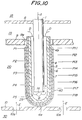
- Fig. 10 is a schematic sectional view illustrating an example of such an SOFC.
- reference numerals 1, 4, 5 and 6 are an oxidizing gas feed pipe for the introduction of an oxidizing gas such as air, a bottom-provided porous support tube, an air electrode, and a solid electrolyte, respectively.
- Reference numerals 7, 8, 9 and 10 are a fuel electrode, an upper plate for holding the oxidizing gas feed pipe 1 and separating an oxidizing gas chamber 18 from an exhaust gas chamber 19, a plate having a gas outflow hole 9a and separating the exhaust gas chamber 19 from a fuel reacting chamber 20, and a bottom plate provided with fuel inflow holes 10a and adapted for holding an SOFC element 40 and separating a cell reacting chamber 20 and a fuel chamber 30, respectively.
- the power generation amount of the SOFC is greatly influenced by the amount of oxygen permeating the bottom-provided porous support tube 4.
- the concentration of oxygen is still high near the oxidizing gas feed opening 1a, the amount of oxygen ions reaching the fuel electrode 7 near there is great, so that the reacting rate between the oxygen ions and the fuel on the surface of the fuel electrode 7 is large to raise the temperature. With this increase in temperature, the reaction on the fuel electrode between the oxygen ions and the fuel gas is further activated.
- the concentration of oxygen in the gas decreases. Consequently, the amount of oxygen ions reaching the surface of the fuel electrode 7 near the gas outflow hole 9a decreases, so that the reaction amount between the oxygen ions and the fuel on the fuel electrode 7 is small to lower the elevation of the temperature. As a result, the reaction is further inactivated due to its lower temperature. This tendency becomes more conspicuous when the bottom-provided SOFC element becomes longer.
- the present invention provides a solid oxide fuel cell as set out in claim 1.
- the present inventors have solved this problem by varying the open porosity of the porous support tube 4 of the SOFC element to make the permeating amount of oxygen substantially uniform in the longitudinal direction.
- the length of the SOFC element 40 becomes further greater, it is necessary to correspondingly increase the open porosity of the porous support tube 4 on the downstream side of the oxidizing gas.
- the strength of the support tube 4 drops. Therefore, there is a limit on the open porosity in the longitudinal direction which the above-mentioned porous support tube 4 is allowed to have.
- the present inventors can realize the elimination of non-uniformity in the reactivity and temperature in the longitudinal direction of the cell and the reduction in the thermal strain and stress, the prolongation of the use life of the cell, and the improvement of the power generation efficiency by this aspect of the present invention in view of the above problems.
- Fig. 1 is a longitudinal sectional view of an embodiment of the SOFC according to the present invention.
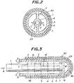
- Fig. 2 is a sectional view of Fig. 1 taken along a line II-II. Same reference numerals as in the SOFC of Fig. 10 are given to the same functional members in this embodiment.
- a plurality of circular holes 2 having the same diameter are arranged in the lateral surface of an oxidizing gas feed pipe 1 in the longitudinal direction thereof.
- Flat plate-like ribs 3 are provided between the outer peripheral surface of the oxidizing gas feed pipe 1 and a porous support tube 4.
- two rows of the flat plate-like ribs are provided as shown in Fig. 2. Therefore, an oxidizing gas fed into the oxidizing gas feed pipe 1 is blown out successively through the circular holes 2 as shown by arrows C.
- the oxidizing gas is utilized for power generation, and then mixed with one coming through an oxidizing gas feed opening la at the tip of the oxidizing gas feed pipe 1 and discharged to an exhaust gas chamber 19 as shown by arrows D.
- An air electrode 5 may be made of LaMnO 3 , CaMnO 3 , LaNiO 3 , LaCoO 3 , LaCrO 3 or the like doped or not doped. Among them, LaMnO 3 added with strontium.
- a solid electrolyte 6 may be generally produced from yttoria-stabilized zirconia or the like.
- a fuel electrode 7 may be generally made of nickel-zirconia cermet or cobalt-zirconia cermet.
- each of the circular holes 2 functions as an oxidizing gas feeding portion, so that fresh oxidizing gas is fed through each of these circular holes 2. Therefore, since fresh oxidizing gas is fed over the entire cylindrical space 29, and is mixed with oxidizing gas having the concentration reduced, the gradient of the concentration of oxygen decreases also due to turbulence of the mixed gas stream. Consequently, the reaction on the electrode is made uniform, and the temperature is also made uniform. Owing to this, the thermal strain and stress can be reduced as a whole, and the electric power generating efficiency can be totally enhanced.
- the oxidizing gas feed pipe 1 is provided separately from the SOFC element 40 in the case of the SOFC having the structure shown in Fig. 10, it is difficult to accurately locate the oxidizing gas feed pipe 1 inside the cylindrical space 29. For this reason, since the location of the oxidizing gas feed pipe 1 varies inside the cylindrical space 29, it changes the flow of the oxidizing gas rising between the outer peripheral surface of the oxidizing gas feed pipe 1 and the inner peripheral surface of the porous support tube 4, which results in variations in the performances among fuel cells.
- the structure is integrated by connecting the oxidizing gas feed pipe 1 with the SOFC element 40 by the flat-plate like ribs 3 in this embodiment, the oxidizing gas feed pipe 1 can be assuredly located inside the cylindrical space 29, so that variations in the performances resulting from changes in positional relationship between the oxidizing gas feed pipe 1 and the SOFC element 40 can completely be diminished.
- the flat plate-like ribs extend radially from the oxidizing gas feed pipe 1, the mechanical strength of the SOFC element 40 can greatly be increased from the standpoint of the structural mechanics.
- a slit 12 having a slender rectangular shape is provided in a lateral face 1b of the oxidizing gas feed pipe 1 as the oxidizing gas feeding portion instead of a plurality of the circular holes, and fresh oxidizing gas is flown out through the slit 12.
- This slit 12 is provided for each of sections divided by the flat plate-like ribs 3.
- a plurality of circular holes 22 are provided, as an oxidizing feeding portion, in the lateral face of an oxidizing gas feed pipe 1, and the diameter of the circular holes 22 is gradually increased from the vicinity of an opening of the SOFC element 40 toward the bottom portion thereof. Accordingly, a phenomenon that since a majority part of the oxidizing gas is flown out through the circular holes 22 near the opening of the SOFC element so that a sufficient amount of the oxidizing gas will not be fed to the vicinity of the bottom portion can be prevented.
- the concentration of the oxidizing gas inside the cylindrical space 29 can be regulated by adjusting the diameter of the circular holes 22.
- a slit 32 is provided as an oxidizing gas feeding portion in the lateral face of an oxidizing gas feed pipe 1 as in the SOFC shown in Fig. 3.
- the width of the slit 32 is decreased near the opening of the SOFC element 40, and gradually increased toward the bottom portion of the SOFC element 40.
- flat plate-like ribs 3A are extended outside from the cylindrical space 29 up to the base portion of the oxidizing gas feed pipe 1. Since the rows of the ribs thus shaped functions as heat-emitting fins, the extended portions can enhance heat exchange efficiency between the oxidizing gas flowing through the oxidizing gas feed pipe 1 and the combustion exhaust gas flowing outside the SOFC element when the oxidizing gas fed through the oxidizing gas feed pipe 1 is to be preliminarily heated at the base portion of the feed pipe. Therefore, since the temperature of the oxidizing gas to be fed into the cylindrical space 29 can further be raised, the heat exchange efficiency of the entire fuel cell can be further improved.
- Fig. 7 is a partially sectional view of a so-called multi-cell type SOFC to which the present invention is applied.
- a plurality of air electrodes 15 are provided on the surface of a bottom-provided porous support tube 4 at a specific interval, and a solid electrolyte 16 and a fuel electrode 17 are successively formed on each of the air electrodes 15.
- the fuel electrodes 17 are successively electrically connected to the adjacent air electrodes 15 by interconnectors 28, respectively.
- the orientation of the circular hole 2 is aligned with a normal to the wall surface of the oxidizing gas feed pipe 1, the oxidizing gas flows out through the circular hole 2 horizontally in Fig. 1.
- the circular hole 2 may be inclined to the normal to the wall surface of the oxidizing gas feed pipe 1 at a given angle.
- the oxidizing gas upwardly or downwardly flows out.
- the orientation of the circular hole is inclined to the normal to the wall surface of the oxidizing feed pipe 1 in the radial direction of the feed pipe 1 (in the lateral direction in Fig. 1), the oxidizing gas flows out in a deviated fashion to the left or the right.
- the fuel cell 7, 17b is positioned outside the air electrode 5, 15 in the above-mentioned embodiments, this electrode arrangement may be reversed. In such a case, the fuel gas is fed into the annular space 29, and the oxidizing gas is fed outside the SOFC element.
- Fig. 1 although the fuel cell element 40 is vertically supported, the entire power generator may be arranged horizontally or inclined at a given angle.
- the air electrode itself is made as a rigid body so that the cell element itself can be structurally independently used.
- the SOFC element can easily be fixed to the fuel cell body by fitting the flange portion to the upper plate 8 when it is used as a fuel cell as shown in Fig. 1.
- the cylindrical space 29 between the oxidizing gas feed pipe and the porous support tube 4 is divided by the flat plate-like ribs 3, it may be possible to extend the flat plate-like ribs to the center of the oxidizing gas feed pipe so that the interior of the oxidizing gas feed pipe may be divided into plural chambers defined by the ribs.
- the circular holes 2, 22, or the slits 12, 32 provided in the lateral face of the oxidizing gas feed pipe 1 are employed as the oxidizing gas feeding portion
- an oxidizing gas feed portion having other constructions may be employed.
- a number of small holes may be provided at random. In this case, if the density of the small holes is increased as the location approaches the bottom portion, effects similar to those in the embodiments of Figs. 4 and 5 can be obtained.
- the SOFC may be fitted not only horizontally or vertically, but also inclined to the fuel cell body at a given angle.
- the gas feed portion for feeding oxidizing gas or fuel gas into the cylindrical space is provided in at least the lateral face of the gas feed pipe, fresh oxidizing gas or fuel gas is fed through the gas feeding portion at the lateral face, and mixed with the gas having the concentration already reduced. Consequently, since the gradient of the concentration of oxygen in the annular space is reduced, the reactivity of the reaction and the temperature on the electrode may be made uniform. Thereby, the thermal stress can be totally reduced, and the entire electric power generation efficiency can be enhanced.
- the open porosity of the bottom-provided porous support tube 4 it is preferable to set the open porosity of the bottom-provided porous support tube 4 to 20-50% at every location. In addition, it is also preferable to set the diameter of pores therein at 1 to 10 ⁇ m.
- the open porosity of the bottom-provided porous support tube 4 is set at more than 50%, strength of the support tube 4 greatly lowers and reliability in long term durability disappears. On the other hand, if the open porosity is set at less than 20%, the power generating efficiency of the SOFC element drops. If the pore diameter of the support tube is more than 10 ⁇ m, strength of the support tube 4 drops, and portions of the fuel cell which contribute to power generation are localized. On the other hand, if it is less than 1 ⁇ m, the permeating amount of the gas drops.
- the bottom-provided porous support tube 4 is assembled on a ceramic setter, and fired inside a furnace.
- Firing conditions of the support tube 4 are appropriately set, although depending upon a desired porosity thereof, such that the heating rate is 20-100°C/h, the firing temperature is 1,400-1,600°C, the firing temperature-keeping time is 30 minutes to 4 hours, and the cooling rate is 20-100°C/h.
- the bottom-provided porous support tube is once fired, and after firing, open pores of the support tube are impregnated and filled with a filler. Then, the support tube is dried or fired.
- An air electrode 5 is made of LaMnO 3 , CaMnO 3 , LaNiO 3 , LaCoO 3 , LaCrO 3 or the like doped or not doped. Among them, LaMnO 3 added with strontium is preferred.
- a solid electrolyte 6 may be generally produced from yttoria-stabilized zirconia or the like.
- a fuel electrode 7 is generally made of nickel-zirconia cermet or cobalt-zirconia cermet.
- air electrodes are provided on the surface of a cylindrical porous support tube at plural locations at a specific interval, a solid electrolyte and a fuel electrode are successively provided on each of the air electrodes, and fuel electrodes are successively electrically connected to the adjacent air electrodes through interconnectors, respectively.
- the porous support tube may be a cylindrical shape, a cylindrical shape with a bottom, a tetragonal prismatic shape, a hexagonal prism or the like.
- a calibrated line showing a relationship between the average open porosity of the bottom-provided porous support tube and the permeating amount of the oxidizing gas is shown in Fig. 9.
- bottom-provided porous support tubes of Figs. 1 and 10 having a length of 1,500 mm were prepared, and an air electrode, a solid electrolyte and a fuel electrode were formed on each of the support tubes to form SOFC elements shown in Figs. 1 and 10.
- each of the SOFC element of the present invention and the conventional SOFC element was placed inside a reacting chamber 20 of a cell.
- the interior of the cell reacting chamber 20 was heated to 1,000°C, and air and methane were fed into the oxidizing gas feed pipe 1 and through the fuel inflow holes 10a, respectively, at their respective constant flow rates. Thereby, oxygen ions were reacted with methane on the surface of the fuel electrode of each of the SOFC elements.
- Temperatures on the surface of the fuel electrode were measured during the reaction at measuring locations P1, P2, P3, P4 and P5, which divided a straight portion of each of the SOFC elements shown in Figs. 1 and 10 into four equal portions, by using thermocouples, and the concentrations of oxygen at locations inside the cylindrical space 29 corresponding to the locations of P1, P2, P3, P4 and P5, respectively were measured by using an O 2 meter. Then, the SOFC element was cooled to room temperature, and the fuel electrode, the solid electrolyte and the air electrode were removed, and the open porosity at P1, P2, P3, P4 and P5 were measured.
- the amount of oxygen penetrated through the bottom-provided porous support tube and applied for the power generation can be made uniform over every location of the bottom-provided porous support tube, and accordingly excellent oxygen-permeability can be imparted upon the support tube.
- the cell reactivity can be made uniform in the longitudinal direction of the SOFC element, and the distribution of temperature can also be made uniform in the longitudinal direction, so that occurrence of cracks can be prevented.
- Figs. 1 and 2 are a longitudinal sectional view of an embodiment of the SOFC element according to this other aspect of the present invention, and a sectional view of Fig. 1 taken along a line II, respectively.
- a plurality of circular holes 2 having the same diameter are provided in the lateral face 1b of an oxidizing gas feed pipe 1 in the longitudinal direction, and flat plate-like ribs 3 are provided between the peripheral surface of the oxidizing gas feed pipe 1 and a porous support tube 4, for example, in two rows. Therefore, the oxidizing gas fed inside the oxidizing gas feed pipe 1 is successively blown out through the circular holes 2 as shown by arrows C. After the oxidizing gas is used for the power generation, the gas is mixed with the oxidizing gas coming out from an oxidizing gas feed opening la, and discharged to the exhaust gas chamber 19 as shown by arrows D.
- the open porosity of the bottom-provided porous support tube 4 is made smaller on the upstream side of the stream of the oxidizing gas flowing inside the cylindrical space 29, and made greater within a given range on the downstream side.
- the air electrode 5 is made of LaMnO 3 , CaMnO 3 , LaNiO 3 , LaCoO 3 , LaCrO 3 or the like doped or not doped. Among them, LaMnO 3 added with strontium is preferred.
- the solid electrolyte 6 may be generally made of yttriastabilized zirconia or the like.
- the fuel electrode 7 may be generally made of nickel-zirconia cermet or cobalt-zirconia cermet.
- each of the circular holes 2 functions as the oxidizing gas feeding portion, so that fresh oxidizing gas is fed through each of the circular holes 2. Therefore, fresh oxidizing gas is fed over the entire cylindrical space 29, and is mixed with the oxidizing gas having the concentration already reduced, so that the gradient of the concentration of oxygen can be reduced also due to the turbulence of the mixed gas stream.
- the porosity of the bottom-provided porous support tube 4 is important to vary from the side of the bottom portion 4a to the side of the end portion 4b for the power generating portion. As shown in Fig. 9, the porosity of the bottom-provided support tube and the permeating amount of the oxidizing gas have the almost straight relationship.
- bottom-provided porous support tubes of Figs. 1 and 10 having a length of 3,000 mm were prepared, and an air electrode, a solid electrolyte and a fuel electrode were formed on each of the support tubes to produce SOFC elements shown in Figs. 1 and 10.
- Each of the invention SOFC element and the conventional SOFC element was placed in a reacting chamber 20 of a cell. Then, the interior of the reacting chamber 20 was heated to 1,000°C, and air and methane were fed to the oxidizing gas feed pipe 1 and through the fuel inflow holes 10a, respectively, at their respective flow rates, so that oxygen ions and methane were reacted on the surface of the fuel electrode of the SOFC element.
- temperatures of the surface of the fuel electrode were measured during the reaction at measuring locations P11, P12, P13, P14, P15, P16, P17 and P18 dividing a straight liner portion of the SOFC element 40 into seven equal portions, by thermocouples, and at the same time the concentrations of oxygen were measured at locations inside the cylindrical space corresponding to the locations of P11, P12, P13, P14, P15, P16, P17 and P18, respectively, by using an O 2 meter. Then, the SOFC element was cooled to room temperature, and the open porosities at the locations P11, P12, P13, P14, P15, P16, P17 and P18 of the bottom-provided porous support tube 4 were measured in the same manner as mentioned before.
- the permeating amounts of the oxidizing gas were calculated from the measurement values of the open porosities at the above locations and the calibration line in Fig. 9, and the permeating amount of oxygen at each location was determined as a produce between the permeating amount of the oxidizing gas and the concentration of oxygen. These results are shown in Tables 3, 4 and 5.
- Table 3 shows results with respect to the case where the open porosity was almost constant in the longitudinal direction of the bottom-provided porous support tube 4, and air was fed through the oxidizing gas feed opening la of the oxidizing gas feed pipe 1 (Fig. 10).
- Table 4 shows the results with respect to the case where the open porosity of the bottom-provided porous support tube 4 in the longitudinal direction was made greater on the portion facing the downstream side of the oxidizing gas and smaller, and the oxidizing gas was fed through the oxidizing gas feed opening la of the oxidizing gas feed pipe 1.
- Table 5 shows results with respect to the case where the open porosity of the bottom-provided porous support tube 4 in the longitudinal direction was made greater in the portion facing the downstream side of the oxidizing gas, and air was fed through the oxidizing gas feed opening 1a of the oxidizing gas feed pipe 1 and the circular holes 2 of the lateral face 1b (Fig. 1).
- Table 5 shows results for the case where the SOFC element employing the support tube 4 produced according to the present invention was used, and air was fed through the gas feed opening la of the gas feed pipe 1 and the circular holes 2 for the measurement. It is seen from Table 5 that since the temperatures of the surface of the fuel cell at the locations Pll through P18 were higher than that of the atmosphere inside the cell reacting chamber 20, and almost identical over the entire surface, the power was almost uniformly generated inside the SOFC element. Further, since the cell reaction occurred at substantially the same temperature in the longitudinal direction of the SOFC element, occurrence of cracks in the SOFC element can be prevented, and reliability in long use can be enhanced.
- Table 6 the relationship between the open porosity and the mechanical strength of the bottom-provided porous support tube is shown in Table 6.
- the flexural strength of the bottom-provided porous support tube was expressed by relative ratio by taking that of the support tube having the average open porosity being 35% as 100.
- Table 6 Open porosity (%) 35.0 42.3 46.8 52.3 Flexural strength 100 89.0 78.0 72.0
- the open porosity of the porous support tube 4 in the longitudinal direction is set at not more than 50%, and the oxidizing gas is fed through the circular holes 2 at the lateral face of the oxidizing gas feed pipe 1 to increase the concentration of oxygen and make the cell reaction in the longitudinal direction of the SOFC element uniform.
- the strength of the SOFC element is maintained high, the concentration of oxygen in the oxidizing gas inside the cylindrical space 29 is made uniform, and the permeability of the oxidizing gas penetrating through the bottom-provided porous support tube 4 from the side of the cylindrical space is controlled.
- the non-uniformity of the electrode reaction can be corrected by skillfully combining these techniques.
- the oxidizing gas feed pipe 1 can be accurately located inside the cylindrical space 29, so that variations in the performances resulting from changes in the positional relationship between the oxidizing gas feed pipe 1 and the SOFC element 40 can be completely diminished.
- the flat plate-like ribs 3 radially extend from the oxidizing gas feed pipe 1, the mechanical strength of the SOFC element 40 is conspicuously increased from the standpoint of the structural mechanics.
- the mechanical strength, particularly, the radial crushing strength of the SOFC element can be favorably further increased.
Landscapes
- Life Sciences & Earth Sciences (AREA)
- Engineering & Computer Science (AREA)
- Manufacturing & Machinery (AREA)
- Sustainable Development (AREA)
- Sustainable Energy (AREA)
- Chemical & Material Sciences (AREA)
- Chemical Kinetics & Catalysis (AREA)
- Electrochemistry (AREA)
- General Chemical & Material Sciences (AREA)
- Fuel Cell (AREA)
Description
- The present invention relates to solid oxide fuel cells.
- Recently, fuel cells have been noted as power generating equipments. Since the fuel cell is an equipment capable of directly converting chemical energy possessed by fuel to electric energy and the fuel cell is free from limitation of Carnot's cycle, the cell is an extremely promising technique in that the fuel cell essentially has a high energy conversion efficiency, a variety of fuels (naphtha, natural gas, methanol, coal reformed gas, heavy oil, etc.) may be used, the cell provokes less public nuisance, and its power generating efficiency is not influenced by the scale of the equipment.
- Particularly, since the solid oxide fuel cell (SOFC) operates at high temperatures of 1,000°C or more, reaction on electrode is extremely active. Thus, completely no catalyst of a noble metal such as expensive platinum is necessary. In addition, since the SOFC has low polarization and relatively high output voltage, its energy conversion efficiency is conspicuously higher than that in the other fuel cells. Furthermore, since their constituent materials are all solid, SOFC is stable and has long use life.
- Fig. 10 is a schematic sectional view illustrating an example of such an SOFC.
- In Fig. 10,
reference numerals Reference numerals gas chamber 18 from anexhaust gas chamber 19, a plate having agas outflow hole 9a and separating theexhaust gas chamber 19 from afuel reacting chamber 20, and a bottom plate provided withfuel inflow holes 10a and adapted for holding anSOFC element 40 and separating acell reacting chamber 20 and afuel chamber 30, respectively. - In this state, when the oxidizing gas such as air is fed from the oxidizing
chamber 18 to the oxidizing gas feed pipe 1 as shown in an arrow A, the oxidizing gas flowing out through an oxidizing gas feed opening la is inverted at a bottom portion 4a (arrows B), and flows through aspace 29 inside the bottom-provided cylindricalporous support tube 4, and discharged out to theexhaust gas chamber 19 as shown by an arrow D. On the other hand, when a fuel gas such as H2 or CH4 is flown along the outer surface of theSOFC element 40 through thefuel inflow openings 10a of thebottom plate 10, the fuel gas reacts with oxygen ions diffusing out through the solid electrolyte react on the surface of thefuel electrode 7. As a result, current flows between theair electrode 5 and thefuel electrode 7, so that the SOFC can be used as a cell. Since this fuel cell is used at high temperatures such as around 1,000°C, it is preferably used in the construction of Fig. 10 which needs no sealed portion. - In order to put the SOFC into practical use, it is necessary that costs are reduced, and electric power density is increased. For this reason, it is required that the length of the
SOFC element 40 is made greater and that the power generation output per one element is increased. - However, when the bottom-provided
tubular SOFC element 40 is prolonged, the temperature gradient becomes greater owing to non-uniform reactivity on the electrode in the longitudinal direction of theSOFC element 40, so that thermal strain and stress become greater to develop cracks in the SOFC element and shorten the use life thereof. - Further, the power generation amount of the SOFC is greatly influenced by the amount of oxygen permeating the bottom-provided
porous support tube 4. - That is, since the concentration of oxygen is still high near the oxidizing gas feed opening 1a, the amount of oxygen ions reaching the
fuel electrode 7 near there is great, so that the reacting rate between the oxygen ions and the fuel on the surface of thefuel electrode 7 is large to raise the temperature. With this increase in temperature, the reaction on the fuel electrode between the oxygen ions and the fuel gas is further activated. On the other hand, as the gas flown out through the oxidizing gas feed opening 1a approaches the side of thegas outflow hole 9a, the concentration of oxygen in the gas decreases. Consequently, the amount of oxygen ions reaching the surface of thefuel electrode 7 near thegas outflow hole 9a decreases, so that the reaction amount between the oxygen ions and the fuel on thefuel electrode 7 is small to lower the elevation of the temperature. As a result, the reaction is further inactivated due to its lower temperature. This tendency becomes more conspicuous when the bottom-provided SOFC element becomes longer. - In addition, with recent improvement on the performances of the fuel cell, support tubes having excellent oxygen-diffusing property have been required.
- Similar problems occur in the case of the SOFC in which a fuel electrode is provided inside a
solid electrolyte 6 and a fuel gas is passed through aspace 29 inside a tube for the power generation, too. In such a case, since a not negligible amount of CO2, steam, etc. are contained in the fuel gas having its concentration reduced, these ingredients attach to the surface of the electrode to hinder the reaction. Thus, the reaction becomes less active, so that the temperature of the SOFC element becomes considerably non-uniform in the longitudinal direction. - It is a first object of the present invention to provide a bottom-provided cylindrical solid oxide fuel cell in which non-uniformity in the reactivity and temperature in the longitudinal direction of the cell is reduced, thermal strain and stress are reduced, and power generation efficiency is enhanced.
- It is a second object of the present invention to provide a cylindrical solid oxide fuel cell in which the permeating amounts of oxygen or fuel can be made uniform over every portion of an SOFC element, the permeating amount of oxygen or fuel is high, and the reactivity can be made uniform in the longitudinal direction of the SOFC element.
- It is a third object of the present invention to provide a bottom-provided cylindrical solid oxide fuel cell in which non-uniformity in the reactivity and temperature in the longitudinal direction of the cell can be lessened, the thermal strain and stress can be reduced, the use life of the cell can be prolonged, and the power generation efficiency can be enhanced.
- The present invention provides a solid oxide fuel cell as set out in claim 1.
- Optional, preferred features of the present invention are set out in the dependent claims.
- In particular the feature of
dependent claim 5 is based on the following recognition. - That is, the tendency that the electrode reaction is active near the oxidizing gas feeding opening la, while the reaction is inactive on the other end becomes more conspicuous as the length of a single bottom-provided cell becomes greater. The present inventors have solved this problem by varying the open porosity of the
porous support tube 4 of the SOFC element to make the permeating amount of oxygen substantially uniform in the longitudinal direction. However, if the length of theSOFC element 40 becomes further greater, it is necessary to correspondingly increase the open porosity of theporous support tube 4 on the downstream side of the oxidizing gas. However, with increase in the open porosity, the strength of thesupport tube 4 drops. Therefore, there is a limit on the open porosity in the longitudinal direction which the above-mentionedporous support tube 4 is allowed to have. - Moreover, even if the flow rate of the oxidizing gas is merely increased in the case of the structure shown in Fig. 10, not only the SOFC element is cooled and the heat efficiency and the power generation efficiency are reduced, but also the SOFC element is likely to be cracked due to thermal strain.
- Similar problems occur in the case of the SOFC in which a fuel electrode is provided inside a
solid electrolyte 6, and a fuel gas is fed into a cylindrical space for power generation, too. In addition, in this case, since not negligible amounts of CO2, steam, etc. are contained in the fuel gas having its concentration reduced, these ingredients are attached to the surface of the electrode to hinder the reaction. Thus, the reaction becomes less active to considerably make the temperature non-uniform. - The present inventors can realize the elimination of non-uniformity in the reactivity and temperature in the longitudinal direction of the cell and the reduction in the thermal strain and stress, the prolongation of the use life of the cell, and the improvement of the power generation efficiency by this aspect of the present invention in view of the above problems.
- These and other objects, features and advantages of the invention will be appreciated upon reading of the following description of the invention when taken in conjunction with the attached drawings.
- For a better understanding of the invention, reference is made to the attached drawings, wherein:
- Fig. 1 is a sectional view of an embodiment of the SOFC according to the present invention;
- Fig. 2 is a sectional view of Fig. 1 taken along a line II-II;
- Figs. 3, 4, 5, 6, 7 and 8 are sectional views of other embodiments of the SOFC according to the present invention;
- Fig. 9 is a graph showing the relationship between the average open porosity of the bottom-provided porous support tube and the permeating amount of an oxidizing gas; and
- Fig. 10 is a sectional view of the conventional SOFC.
- Fig. 1 is a longitudinal sectional view of an embodiment of the SOFC according to the present invention. Fig. 2 is a sectional view of Fig. 1 taken along a line II-II. Same reference numerals as in the SOFC of Fig. 10 are given to the same functional members in this embodiment.
- In the SOFC, a plurality of
circular holes 2 having the same diameter are arranged in the lateral surface of an oxidizing gas feed pipe 1 in the longitudinal direction thereof. Flat plate-like ribs 3 are provided between the outer peripheral surface of the oxidizing gas feed pipe 1 and aporous support tube 4. For instance, two rows of the flat plate-like ribs are provided as shown in Fig. 2. Therefore, an oxidizing gas fed into the oxidizing gas feed pipe 1 is blown out successively through thecircular holes 2 as shown by arrows C. The oxidizing gas is utilized for power generation, and then mixed with one coming through an oxidizing gas feed opening la at the tip of the oxidizing gas feed pipe 1 and discharged to anexhaust gas chamber 19 as shown by arrows D. - An
air electrode 5 may be made of LaMnO3, CaMnO3, LaNiO3, LaCoO3, LaCrO3 or the like doped or not doped. Among them, LaMnO3 added with strontium. Asolid electrolyte 6 may be generally produced from yttoria-stabilized zirconia or the like. Afuel electrode 7 may be generally made of nickel-zirconia cermet or cobalt-zirconia cermet. - According to the SOFC in this embodiment, the following effects can be obtained.
- (1) As mentioned above, as the location goes away from the oxidizing gas feed opening in the prior art, the concentration of the oxidizing gas inside the
cylindrical space 29 decreases, so that the electrochemical reaction is decreased and the temperature is correspondingly lowered. - In contrast, according to the present embodiment, since a plurality of the
circular holes 2 are successively provided in the lateral face of the oxidizing gas feed pipe 1 in the longitudinal direction, each of thecircular holes 2 functions as an oxidizing gas feeding portion, so that fresh oxidizing gas is fed through each of thesecircular holes 2. Therefore, since fresh oxidizing gas is fed over the entirecylindrical space 29, and is mixed with oxidizing gas having the concentration reduced, the gradient of the concentration of oxygen decreases also due to turbulence of the mixed gas stream. Consequently, the reaction on the electrode is made uniform, and the temperature is also made uniform. Owing to this, the thermal strain and stress can be reduced as a whole, and the electric power generating efficiency can be totally enhanced. - (2) Since the oxidizing gas feed pipe 1 is provided separately from the
SOFC element 40 in the case of the SOFC having the structure shown in Fig. 10, it is difficult to accurately locate the oxidizing gas feed pipe 1 inside thecylindrical space 29. For this reason, since the location of the oxidizing gas feed pipe 1 varies inside thecylindrical space 29, it changes the flow of the oxidizing gas rising between the outer peripheral surface of the oxidizing gas feed pipe 1 and the inner peripheral surface of theporous support tube 4, which results in variations in the performances among fuel cells. - In contrast, since the structure is integrated by connecting the oxidizing gas feed pipe 1 with the
SOFC element 40 by the flat-plate likeribs 3 in this embodiment, the oxidizing gas feed pipe 1 can be assuredly located inside thecylindrical space 29, so that variations in the performances resulting from changes in positional relationship between the oxidizing gas feed pipe 1 and theSOFC element 40 can completely be diminished. In addition, since the flat plate-like ribs extend radially from the oxidizing gas feed pipe 1, the mechanical strength of theSOFC element 40 can greatly be increased from the standpoint of the structural mechanics. - When three or more rows of the flat plate-
like ribs 3 are provided and an angle between theadjacent ribs 3 is smaller than 180°, it is more preferable in further increasing the mechanical strength, particularly, the radial crushing strength of the SOFC element. - In an SOFC shown in Fig. 3, a
slit 12 having a slender rectangular shape is provided in a lateral face 1b of the oxidizing gas feed pipe 1 as the oxidizing gas feeding portion instead of a plurality of the circular holes, and fresh oxidizing gas is flown out through theslit 12. This slit 12 is provided for each of sections divided by the flat plate-like ribs 3. - In Fig. 4, a plurality of
circular holes 22 are provided, as an oxidizing feeding portion, in the lateral face of an oxidizing gas feed pipe 1, and the diameter of thecircular holes 22 is gradually increased from the vicinity of an opening of theSOFC element 40 toward the bottom portion thereof. Accordingly, a phenomenon that since a majority part of the oxidizing gas is flown out through thecircular holes 22 near the opening of the SOFC element so that a sufficient amount of the oxidizing gas will not be fed to the vicinity of the bottom portion can be prevented. The concentration of the oxidizing gas inside thecylindrical space 29 can be regulated by adjusting the diameter of the circular holes 22. - In the SOFC in Fig. 5, a
slit 32 is provided as an oxidizing gas feeding portion in the lateral face of an oxidizing gas feed pipe 1 as in the SOFC shown in Fig. 3. The width of theslit 32 is decreased near the opening of theSOFC element 40, and gradually increased toward the bottom portion of theSOFC element 40. By employingsuch slits 32, effects similar to those obtained by the embodiment in Fig. 4 can be attained. - In the SOFC shown in Fig. 6, flat plate-
like ribs 3A are extended outside from thecylindrical space 29 up to the base portion of the oxidizing gas feed pipe 1. Since the rows of the ribs thus shaped functions as heat-emitting fins, the extended portions can enhance heat exchange efficiency between the oxidizing gas flowing through the oxidizing gas feed pipe 1 and the combustion exhaust gas flowing outside the SOFC element when the oxidizing gas fed through the oxidizing gas feed pipe 1 is to be preliminarily heated at the base portion of the feed pipe. Therefore, since the temperature of the oxidizing gas to be fed into thecylindrical space 29 can further be raised, the heat exchange efficiency of the entire fuel cell can be further improved. - Fig. 7 is a partially sectional view of a so-called multi-cell type SOFC to which the present invention is applied.
- A plurality of
air electrodes 15 are provided on the surface of a bottom-providedporous support tube 4 at a specific interval, and asolid electrolyte 16 and afuel electrode 17 are successively formed on each of theair electrodes 15. Thefuel electrodes 17 are successively electrically connected to theadjacent air electrodes 15 byinterconnectors 28, respectively. - The above-mentioned embodiments may be modified in various manners.
- In Figs. 1, 4, 6 and 7, the orientation of the
circular hole 2 is aligned with a normal to the wall surface of the oxidizing gas feed pipe 1, the oxidizing gas flows out through thecircular hole 2 horizontally in Fig. 1. Alternatively, thecircular hole 2 may be inclined to the normal to the wall surface of the oxidizing gas feed pipe 1 at a given angle. Further, when the circular hole is inclined to the normal to the wall surface of the oxidizing feed pipe 1 in the longitudinal direction (in a vertical direction in Fig. 1), the oxidizing gas upwardly or downwardly flows out. When the orientation of the circular hole is inclined to the normal to the wall surface of the oxidizing feed pipe 1 in the radial direction of the feed pipe 1 (in the lateral direction in Fig. 1), the oxidizing gas flows out in a deviated fashion to the left or the right. - That is, for example, as shown in Fig. 8, when the oxidizing gas feed holes 42 provided in the lateral face of the oxidizing gas feed pipe 1 are inclined and the oxidizing gas is flown out toward the bottom in an inclined direction as shown by arrows C, this oxidizing gas stream is crushed with that flowing from the bottom portion as shown by arrows B. Consequently, stirs and make turbulent the former oxidizing gas stream is stirred and converted to turbulence by the latter, so that the gradient of the concentration of oxygen can be made further smaller by this stirring effect.
- Although the
fuel cell 7, 17b is positioned outside theair electrode annular space 29, and the oxidizing gas is fed outside the SOFC element. - In Fig. 1, although the
fuel cell element 40 is vertically supported, the entire power generator may be arranged horizontally or inclined at a given angle. - In the above-mentioned embodiments, although a single cell is formed by using the porous bottom-provided tube, the air electrode itself is made as a rigid body so that the cell element itself can be structurally independently used.
- In Figs. 3 through 6, if a flange portion is provided at the left terminal end of the oxidizing gas feed pipe 1, the SOFC element can easily be fixed to the fuel cell body by fitting the flange portion to the
upper plate 8 when it is used as a fuel cell as shown in Fig. 1. - Further, although only the
cylindrical space 29 between the oxidizing gas feed pipe and theporous support tube 4 is divided by the flat plate-like ribs 3, it may be possible to extend the flat plate-like ribs to the center of the oxidizing gas feed pipe so that the interior of the oxidizing gas feed pipe may be divided into plural chambers defined by the ribs. - By so doing, when a film is to be partially formed on the surface of a porous support tube through gas phase reaction as in the interconnectors for the fuel cell, the partial film formation is possible by flowing the reactive gas through only that of chambers (sections) which corresponds to the portion upon which the film is to be formed. Thus, conventional masking may be omitted.
- Furthermore, in the above-mentioned embodiments, although the
circular holes slits - According to the solid oxide fuel cell in the present invention, since the gas feed portion for feeding oxidizing gas or fuel gas into the cylindrical space is provided in at least the lateral face of the gas feed pipe, fresh oxidizing gas or fuel gas is fed through the gas feeding portion at the lateral face, and mixed with the gas having the concentration already reduced. Consequently, since the gradient of the concentration of oxygen in the annular space is reduced, the reactivity of the reaction and the temperature on the electrode may be made uniform. Thereby, the thermal stress can be totally reduced, and the entire electric power generation efficiency can be enhanced.
- Further, it is preferable to set the open porosity of the bottom-provided
porous support tube 4 to 20-50% at every location. In addition, it is also preferable to set the diameter of pores therein at 1 to 10 µm. - If the open porosity of the bottom-provided
porous support tube 4 is set at more than 50%, strength of thesupport tube 4 greatly lowers and reliability in long term durability disappears. On the other hand, if the open porosity is set at less than 20%, the power generating efficiency of the SOFC element drops. If the pore diameter of the support tube is more than 10 µm, strength of thesupport tube 4 drops, and portions of the fuel cell which contribute to power generation are localized. On the other hand, if it is less than 1 µm, the permeating amount of the gas drops. - The bottom-provided
porous support tube 4 is assembled on a ceramic setter, and fired inside a furnace. - Firing conditions of the
support tube 4 are appropriately set, although depending upon a desired porosity thereof, such that the heating rate is 20-100°C/h, the firing temperature is 1,400-1,600°C, the firing temperature-keeping time is 30 minutes to 4 hours, and the cooling rate is 20-100°C/h. - The bottom-provided porous support tube is once fired, and after firing, open pores of the support tube are impregnated and filled with a filler. Then, the support tube is dried or fired.
- An
air electrode 5 is made of LaMnO3, CaMnO3, LaNiO3, LaCoO3, LaCrO3 or the like doped or not doped. Among them, LaMnO3 added with strontium is preferred. Asolid electrolyte 6 may be generally produced from yttoria-stabilized zirconia or the like. Afuel electrode 7 is generally made of nickel-zirconia cermet or cobalt-zirconia cermet. - In the multi-cell type SOFC, air electrodes are provided on the surface of a cylindrical porous support tube at plural locations at a specific interval, a solid electrolyte and a fuel electrode are successively provided on each of the air electrodes, and fuel electrodes are successively electrically connected to the adjacent air electrodes through interconnectors, respectively.
- The porous support tube may be a cylindrical shape, a cylindrical shape with a bottom, a tetragonal prismatic shape, a hexagonal prism or the like.
- In the following, a further concrete embodiment will be explained.
- First, a calibrated line showing a relationship between the average open porosity of the bottom-provided porous support tube and the permeating amount of the oxidizing gas is shown in Fig. 9.
- In a graph of Fig. 9, the permeability of the oxidizing gas is expressed by relative ratio taking that at the average open porosity of the bottom-provided porous support tube being 35% as 100. As is seen from Fig. 12, both of them have a nearly straight line relationship.
- Next, bottom-provided porous support tubes of Figs. 1 and 10 having a length of 1,500 mm were prepared, and an air electrode, a solid electrolyte and a fuel electrode were formed on each of the support tubes to form SOFC elements shown in Figs. 1 and 10. Then, each of the SOFC element of the present invention and the conventional SOFC element was placed inside a reacting
chamber 20 of a cell. The interior of thecell reacting chamber 20 was heated to 1,000°C, and air and methane were fed into the oxidizing gas feed pipe 1 and through thefuel inflow holes 10a, respectively, at their respective constant flow rates. Thereby, oxygen ions were reacted with methane on the surface of the fuel electrode of each of the SOFC elements. - Temperatures on the surface of the fuel electrode were measured during the reaction at measuring locations P1, P2, P3, P4 and P5, which divided a straight portion of each of the SOFC elements shown in Figs. 1 and 10 into four equal portions, by using thermocouples, and the concentrations of oxygen at locations inside the
cylindrical space 29 corresponding to the locations of P1, P2, P3, P4 and P5, respectively were measured by using an O2 meter. Then, the SOFC element was cooled to room temperature, and the fuel electrode, the solid electrolyte and the air electrode were removed, and the open porosity at P1, P2, P3, P4 and P5 were measured. - The permeating amounts of the oxidizing gas at the above locations were calculated from the measured values of the open porosities at the above locations and the calibrated line in Fig. 9, respectively. Further, the permeating amount of oxygen at each of these locations was determined as a product between the permeating amount of the oxidizing gas and the concentration of oxygen at each location. These results are shown in Tables 1 and 2 below.
Table 1 SOFC in Fig. 10 Location P1 P2 P3 P4 P5 Open porosity (%) 35.2 35.0 35.0 35.1 35.3 Penetrating amount of oxidizing gas 100.6 100 100 100.3 100.9 Oxygen concentration (%) 16.8 17.5 18.4 19.2 20 Penetrating amount of oxygen 16.9 17.5 18.4 19.3 20.2 Surface temperature of fuel electrode (°C) 1000 1010 1025 1052 1076 Table 2 SOFC in Fig. 1 Location P1 P2 P3 P4 P5 Open porosity (%) 40.6 39.0 37.5 36.1 35.0 Penetrating amount of oxidizing gas 116 111.4 107.1 103.1 100 Oxygen concentration (%) 16.8 17.5 18.4 19.2 20 Penetrating amount of oxygen 19.5 19.5 19.7 19.8 20 Surface temperature of fuel electrode (°C) 1055 1058 1060 1062 1068 - It is seen from Table 1 that since the amount of oxygen ions fed onto the surface of the fuel electrode near P5 was greater, the degree of reaction between methane as the fuel gas rose, so that the temperature of the surface of the fuel electrode was far higher than that in the atmosphere inside the cell reacting chamber 20 (1,000°C). On the other hand, Table 1 also shows that the temperature of the surface of the fuel electrode near P1 was near to that in the atmosphere in the
cell reaction chamber 20, so that the cell reaction was inactive. - On the other hand, as seen from the results in Table 2, since the temperature of the surface of the fuel electrode was higher than that of the atmosphere in the
cell reacting chamber 20, and almost identical over the entire surface of the fuel electrode in the case of the SOFC element using thesupport tube 4 prepared according to the present invention. Therefore, it is seen that when the permeating amounts of oxygen at the locations of P1, P2, P3, P4 and P5 are made almost identical, the cell reaction is uniformly effected at every location. - It is clear from the above results that according to the present invention, the amount of oxygen penetrated through the bottom-provided porous support tube and applied for the power generation can be made uniform over every location of the bottom-provided porous support tube, and accordingly excellent oxygen-permeability can be imparted upon the support tube. As a result, the cell reactivity can be made uniform in the longitudinal direction of the SOFC element, and the distribution of temperature can also be made uniform in the longitudinal direction, so that occurrence of cracks can be prevented.
- In the following, another aspect of the present invention will be explained based on Figs. 1 through 5, 7, 8 and 10 used to illustrate the first aspect of the present invention. Same reference numerals in Fig. 10 are given to the same functional members as those in these figures.
- Figs. 1 and 2 are a longitudinal sectional view of an embodiment of the SOFC element according to this other aspect of the present invention, and a sectional view of Fig. 1 taken along a line II, respectively.
- In Fig. 1, a plurality of
circular holes 2 having the same diameter are provided in the lateral face 1b of an oxidizing gas feed pipe 1 in the longitudinal direction, and flat plate-like ribs 3 are provided between the peripheral surface of the oxidizing gas feed pipe 1 and aporous support tube 4, for example, in two rows. Therefore, the oxidizing gas fed inside the oxidizing gas feed pipe 1 is successively blown out through thecircular holes 2 as shown by arrows C. After the oxidizing gas is used for the power generation, the gas is mixed with the oxidizing gas coming out from an oxidizing gas feed opening la, and discharged to theexhaust gas chamber 19 as shown by arrows D. - In this embodiment, the open porosity of the bottom-provided
porous support tube 4 is made smaller on the upstream side of the stream of the oxidizing gas flowing inside thecylindrical space 29, and made greater within a given range on the downstream side. - The
air electrode 5 is made of LaMnO3, CaMnO3, LaNiO3, LaCoO3, LaCrO3 or the like doped or not doped. Among them, LaMnO3 added with strontium is preferred. Thesolid electrolyte 6 may be generally made of yttriastabilized zirconia or the like. Thefuel electrode 7 may be generally made of nickel-zirconia cermet or cobalt-zirconia cermet. - According to the SOFC in this embodiment, the following effects can be obtained.
- (1) As mentioned above, in the prior art, as the location inside
cylindrical space 29 goes apart from the oxidizing gas feed opening, the concentration of the oxidizing gas decreases, the electrochemical reaction drops, and accordingly the temperature lowers. That is, when the oxidizing gas is discharged through the feeding opening of theSOFC element 40 in Fig. 10, for example, about 20% of oxygen contained in the oxidizing gas is consumed, and the reaction on the electrode is largely non-uniform. This tendency becomes more conspicuous with increase in the length of the SOFC element. - In contrast, since a plurality of the
circular holes 2 are provided on the lateral face 1b of the oxidizing gas feed pipe 1 in the longitudinal direction in the case of the present embodiment, each of thecircular holes 2 functions as the oxidizing gas feeding portion, so that fresh oxidizing gas is fed through each of thecircular holes 2. Therefore, fresh oxidizing gas is fed over the entirecylindrical space 29, and is mixed with the oxidizing gas having the concentration already reduced, so that the gradient of the concentration of oxygen can be reduced also due to the turbulence of the mixed gas stream. - In addition, it is important to vary the open porosity of the bottom-provided
porous support tube 4 from the side of the bottom portion 4a to the side of theend portion 4b for the power generating portion. As shown in Fig. 9, the porosity of the bottom-provided support tube and the permeating amount of the oxidizing gas have the almost straight relationship. - Next, bottom-provided porous support tubes of Figs. 1 and 10 having a length of 3,000 mm were prepared, and an air electrode, a solid electrolyte and a fuel electrode were formed on each of the support tubes to produce SOFC elements shown in Figs. 1 and 10. Each of the invention SOFC element and the conventional SOFC element was placed in a reacting
chamber 20 of a cell. Then, the interior of the reactingchamber 20 was heated to 1,000°C, and air and methane were fed to the oxidizing gas feed pipe 1 and through thefuel inflow holes 10a, respectively, at their respective flow rates, so that oxygen ions and methane were reacted on the surface of the fuel electrode of the SOFC element. - Then, temperatures of the surface of the fuel electrode were measured during the reaction at measuring locations P11, P12, P13, P14, P15, P16, P17 and P18 dividing a straight liner portion of the
SOFC element 40 into seven equal portions, by thermocouples, and at the same time the concentrations of oxygen were measured at locations inside the cylindrical space corresponding to the locations of P11, P12, P13, P14, P15, P16, P17 and P18, respectively, by using an O2 meter. Then, the SOFC element was cooled to room temperature, and the open porosities at the locations P11, P12, P13, P14, P15, P16, P17 and P18 of the bottom-providedporous support tube 4 were measured in the same manner as mentioned before. - The permeating amounts of the oxidizing gas were calculated from the measurement values of the open porosities at the above locations and the calibration line in Fig. 9, and the permeating amount of oxygen at each location was determined as a produce between the permeating amount of the oxidizing gas and the concentration of oxygen. These results are shown in Tables 3, 4 and 5.
- Table 3 shows results with respect to the case where the open porosity was almost constant in the longitudinal direction of the bottom-provided
porous support tube 4, and air was fed through the oxidizing gas feed opening la of the oxidizing gas feed pipe 1 (Fig. 10). - Table 4 shows the results with respect to the case where the open porosity of the bottom-provided
porous support tube 4 in the longitudinal direction was made greater on the portion facing the downstream side of the oxidizing gas and smaller, and the oxidizing gas was fed through the oxidizing gas feed opening la of the oxidizing gas feed pipe 1. - Table 5 shows results with respect to the case where the open porosity of the bottom-provided
porous support tube 4 in the longitudinal direction was made greater in the portion facing the downstream side of the oxidizing gas, and air was fed through the oxidizing gas feed opening 1a of the oxidizing gas feed pipe 1 and thecircular holes 2 of the lateral face 1b (Fig. 1).
- It is seen from Table 3 that the amount of oxygen ions fed onto the surface of the fuel electrode near P18 was great, the reaction rate between methane gas as the fuel gas was high, and consequently the temperature of the surface of the fuel electrode was far greater than that (1,000°C) of the atmosphere in the
cell reacting chamber 20. The amount of oxygen ions fed onto the surface of the fuel electrode decreased toward the downstream side in the order of P17, P16, P15 and P14, and accordingly the reaction amount between the fuel gas decreased. Consequently, the temperature of the surface of the fuel electrode at each of these locations dropped.
- It is seen from Table 4 that the differences in temperature of the surface of the fuel electrodes among P11 through P18 were greatly reduced, which enhanced practical applicability. However, since the very long element having a length of as much as 3 m was used, insufficient points remained in realizing uniform power generation of the SOFC element.

- Table 5 shows results for the case where the SOFC element employing the
support tube 4 produced according to the present invention was used, and air was fed through the gas feed opening la of the gas feed pipe 1 and thecircular holes 2 for the measurement. It is seen from Table 5 that since the temperatures of the surface of the fuel cell at the locations Pll through P18 were higher than that of the atmosphere inside thecell reacting chamber 20, and almost identical over the entire surface, the power was almost uniformly generated inside the SOFC element. Further, since the cell reaction occurred at substantially the same temperature in the longitudinal direction of the SOFC element, occurrence of cracks in the SOFC element can be prevented, and reliability in long use can be enhanced. - Next, the relationship between the open porosity and the mechanical strength of the bottom-provided porous support tube is shown in Table 6. In Table 6, the flexural strength of the bottom-provided porous support tube was expressed by relative ratio by taking that of the support tube having the average open porosity being 35% as 100.
Table 6 Open porosity (%) 35.0 42.3 46.8 52.3 Flexural strength 100 89.0 78.0 72.0 - When the open porosity exceeds 50%, the strength of the
porous support tube 4 reached only about 70% of the strength at the open porosity of 35% of theporous support tube 4, so that the reliability of the SOFC element for the long use is deteriorated. Therefore, it is important that the open porosity of theporous support tube 4 in the longitudinal direction is set at not more than 50%, and the oxidizing gas is fed through thecircular holes 2 at the lateral face of the oxidizing gas feed pipe 1 to increase the concentration of oxygen and make the cell reaction in the longitudinal direction of the SOFC element uniform. - As mentioned above, according to the SOFC element in this embodiment, the strength of the SOFC element is maintained high, the concentration of oxygen in the oxidizing gas inside the
cylindrical space 29 is made uniform, and the permeability of the oxidizing gas penetrating through the bottom-providedporous support tube 4 from the side of the cylindrical space is controlled. The non-uniformity of the electrode reaction can be corrected by skillfully combining these techniques. By so doing, since the heat generation can be made uniform in the entire bottom-providedporous support tube 4, the thermal strain and stress can be reduced, the use life of the SOFC element can be prolonged by preventing cracking, and the power generating efficiency can be improved. - (2) As mentioned before, since the oxidizing gas feed pipe 1 is separately provided from the SOFC element in the SOFC having the structure shown in Fig. 10, it is very difficult to accurately locate the oxidizing gas feed pipe 1 inside the
cylindrical space 29. Owing to this, since the oxidizing gas feed pipe 1 varies its location inside thecylindrical space 29, the flow of the oxidizing gas rising between the outer peripheral surface of the oxidizing gas feed pipe 1 and the inner peripheral surface of theporous support tube 4 is varied, so that the performances of the cells vary among them. - In contrast, according to the present embodiment, since the structure is integrated by connecting the oxidizing gas feed pipe 1 with the
SOFC element 40 by means of the flat plate-like ribs 3, the oxidizing gas feed pipe 1 can be accurately located inside thecylindrical space 29, so that variations in the performances resulting from changes in the positional relationship between the oxidizing gas feed pipe 1 and theSOFC element 40 can be completely diminished. In addition, since the flat plate-like ribs 3 radially extend from the oxidizing gas feed pipe 1, the mechanical strength of theSOFC element 40 is conspicuously increased from the standpoint of the structural mechanics. - When the flat plate-
like ribs 3 are provided in three or more rows, and the angle formed between the adjacent ribs is set at not more than 180°, the mechanical strength, particularly, the radial crushing strength of the SOFC element can be favorably further increased.
Claims (9)
- A solid oxide fuel cell comprising a cylindrical solid oxide fuel cell element having a closed end and including at least an air electrode (5,15,25), a solid electrolyte (6,16,26), and a fuel electrode (7,17,27), a gas feed pipe (1,61) inserted into the cylindrical space of said element and having a gas feed portion comprising at least one aperture (2,12,22,32,42) for feeding an oxidizing gas or a fuel gas into said cylindrical space, wherein said gas feed portion is provided at least partly in a lateral wall of the gas feed pipe (1,61),
characterised in that said gas feed portion is constituted at least partly by (i) an aperture array constituted by a plurality of apertures (2,22,42) in said gas feed pipe (1) which apertures are spaced longitudinally of said pipe or (ii) at least one slit-shaped aperture (12,32) whose slit direction extends longitudinally of said pipe (1), said aperture array or said slit-shaped aperture extending over the whole portion of said gas feed pipe where said electrodes (5,15,25,7,17,27) are provided on said fuel cell element, and at least in case (ii), the end of said gas feed pipe (1) extending into said cylindrical space is spaced from said closed end of said fuel cell element. - A solid oxide fuel cell according to claim 1, wherein said gas feed portion is formed at least partly by one of:(a) a plurality of circular apertures (2) having the same diameter and provided in the lateral wall of the gas feed pipe (1) and spaced in the longitudinal direction thereof,(b) at least one slit-shaped aperture (12) having a narrow rectangular shape and provided in the lateral wall of the gas feed pipe (1) and extending in the longitudinal direction thereof,(c) a plurality of circular apertures (22) provided in the lateral wall of the gas feed pipe (1) and spaced in the longitudinal direction thereof, the diameters of said circular holes (22) increasing towards the closed end of the fuel cell element,(d) at least one slit-shaped aperture (32) provided in the lateral wall of the gas feed pipe (1) and extending in the longitudinal direction thereof, the width of said slit-shaped aperture (32) increasing towards said closed end from the side of said fuel cell element, and(e) a plurality of gas feeding apertures (42) provided in the lateral wall of the gas feed pipe (1), said gas feeding apertures (42) being inclined towards said closed end of said fuel cell element in the radially outward direction.
- A solid oxide fuel cell according to claim 1 or claim 2, wherein at least two flat walls (3,3A) extending longitudinally of said cylindrical space are provided to connect the inner peripheral face of the solid oxide fuel cell element with the outer peripheral face of said gas feed pipe (1), and said gas feed portion supplies gas to each of the spaces defined by the inner peripheral face of the cell element, the outer peripheral face of the gas feed pipe (1) and said flat walls (3,3A).
- A solid oxide fuel cell according to any one of claims 1 to 3 having a plurality of said air electrodes (15) formed on an outer peripheral surface of said fuel cell element at plural locations at intervals in the longitudinal direction thereof, a plurality of said solid electrolytes (16) and said fuel electrodes (17) are successively formed on said air electrodes (15) in this order to form cell units, and the fuel electrode (17) of each cell unit is electrically connected to the air electrode (15) of an adjacent cell unit through an interconnector (28) .
- A solid oxide fuel cell according to any one of claims 1 to 4 wherein said solid oxide fuel element comprises a porous cylindrical support tube (4,24) having a closed end, said air electrode (5,25), solid electrolyte (6,26) and fuel electrode (7,27) being formed on an outer peripheral surface of the support tube (4,24), said cell in use receiving a flow of a gas from said gas feed pipe (1,16), said flow passing along the cylindrical space (29) within said porous cylindrical support tube in the direction away from said closed end, and wherein the gas permeation rate through a first portion of the porous cylindrical support tube (4,24) is smaller than the gas permeation rate through a second portion of the porous cylindrical support tube (4,24) which is more remote from said closed end than said first portion.
- A solid oxide fuel cell according to claim 5, wherein the open porosity of the porous cylindrical support tube (4,24) is smaller at said first portion thereof than said second portion thereof.
- A solid oxide fuel cell according to claim 6, wherein the open porosity of the porous support tube (4,24) is in the range 20-50% at every portion thereof.
- A solid oxide fuel cell according to claim 6 or claim 7, wherein the diameter of pores of the porous support tube is in the range 1-10 µm.
- A solid oxide fuel cell according to any one of claims 6 to 8, wherein the difference in the open porosity between a bottom portion and an end portion on an opening side of a power generating portion of the porous support tube (4) meets the following relations: when 1.0≤x≤2.2, 2.3x2-1.2≤y≤3.4x2-1.7, and when 2.2<x≤3.0, x2+5.1<y≤1.5 in which x is the length (m) of the support tube, and y is the difference (%) in the open porosity between the bottom portion and the open end portion.
Applications Claiming Priority (6)
| Application Number | Priority Date | Filing Date | Title |
|---|---|---|---|
| JP32383/90 | 1990-02-15 | ||
| JP2032383A JPH0758618B2 (en) | 1990-02-15 | 1990-02-15 | Solid oxide fuel cell |
| JP75601/90 | 1990-03-27 | ||
| JP2075601A JP2597730B2 (en) | 1990-03-27 | 1990-03-27 | Method for producing bottomed porous support tube for solid oxide fuel cell |
| JP76710/90 | 1990-03-28 | ||
| JP2076710A JPH03280359A (en) | 1990-03-28 | 1990-03-28 | Fuel cell with solid electrolyte |
Publications (2)
| Publication Number | Publication Date |
|---|---|
| EP0442740A1 EP0442740A1 (en) | 1991-08-21 |
| EP0442740B1 true EP0442740B1 (en) | 1996-09-04 |
Family
ID=27287677
Family Applications (1)
| Application Number | Title | Priority Date | Filing Date |
|---|---|---|---|
| EP91301208A Expired - Lifetime EP0442740B1 (en) | 1990-02-15 | 1991-02-14 | Solid oxide fuel cells |
Country Status (4)
| Country | Link |
|---|---|
| US (1) | US5158837A (en) |
| EP (1) | EP0442740B1 (en) |
| CA (1) | CA2036258C (en) |
| DE (1) | DE69121735T2 (en) |
Families Citing this family (16)
| Publication number | Priority date | Publication date | Assignee | Title |
|---|---|---|---|---|
| US5677265A (en) * | 1995-03-03 | 1997-10-14 | Northeastern University | Process for oxygenation of ceramic high Tc superconductors |
| US5595834A (en) * | 1995-09-01 | 1997-01-21 | The Regents Of The University Of Calif. | Annular feed air breathing fuel cell stack |
| US5514486A (en) * | 1995-09-01 | 1996-05-07 | The Regents Of The University Of California, Office Of Technology Transfer | Annular feed air breathing fuel cell stack |
| US6379485B1 (en) * | 1998-04-09 | 2002-04-30 | Siemens Westinghouse Power Corporation | Method of making closed end ceramic fuel cell tubes |
| US6383350B1 (en) * | 2000-07-26 | 2002-05-07 | Northrop Grumman Corporation | Thin film modular electrochemical apparatus and method of manufacture therefor |
| DE10136710A1 (en) * | 2001-07-27 | 2003-02-13 | Siemens Ag | High-temperature fuel cell reactor for high-power density cells has individual tubes coupled in sequence according to flow and devices to conduct air into a first tube and out of a second |
| DE10229820B4 (en) * | 2002-06-28 | 2004-12-30 | Deutsches Zentrum für Luft- und Raumfahrt e.V. | Gas distribution device for an electrochemical electrode and method for applying reactive gas to an electrochemical electrode |
| EP1469542A1 (en) * | 2003-04-09 | 2004-10-20 | Matsushita Electric Industrial Co., Ltd. | Polymer electrolyte fuel cell |
| JP4617711B2 (en) * | 2004-04-30 | 2011-01-26 | 日産自動車株式会社 | Fuel cell |
| JP4965066B2 (en) | 2004-08-19 | 2012-07-04 | 株式会社日立製作所 | Fuel cell |
| US7966830B2 (en) * | 2006-06-29 | 2011-06-28 | The Boeing Company | Fuel cell/combustor systems and methods for aircraft and other applications |
| US8048583B2 (en) * | 2006-07-20 | 2011-11-01 | Modine Manufacturing Company | Compact air preheater for solid oxide fuel cell systems |
| US20090253007A1 (en) * | 2008-04-04 | 2009-10-08 | Mergler Christopher M | Method and apparatus for anode oxidation prevention and cooling of a solid-oxide fuel cell stack |
| US20160329587A1 (en) * | 2015-05-07 | 2016-11-10 | Lg Fuel Cell Systems, Inc. | Fuel cell system |
| CN111403763B (en) * | 2020-03-31 | 2021-05-18 | 西安交通大学 | Metal thin-walled tube-supported microtube solid oxide fuel cells and cell stack structures |
| CN114122471B (en) * | 2021-11-26 | 2023-12-19 | 江苏科技大学 | A methanol solid oxide fuel cell and a power generation system containing the fuel cell |
Family Cites Families (10)
| Publication number | Priority date | Publication date | Assignee | Title |
|---|---|---|---|---|
| FR35016E (en) * | 1929-10-30 | |||
| BE639862A (en) * | 1961-12-05 | 1900-01-01 | ||
| DE2614727A1 (en) * | 1976-04-06 | 1977-10-27 | Bbc Brown Boveri & Cie | Solid electrolyte battery using electrochemical oxidn. - of hydrogen (cpd.) has cells pressed end-to-end by spring and connected in series |
| ZA814990B (en) * | 1980-12-22 | 1982-11-24 | Westinghouse Electric Corp | Fuel cell generator |
| US4463067A (en) * | 1982-09-30 | 1984-07-31 | Engelhard Corporation | Fuel cell and system for supplying electrolyte thereto utilizing cascade feed |
| JPS5963664A (en) * | 1982-10-01 | 1984-04-11 | Kureha Chem Ind Co Ltd | Electrode substrate for fuel cell |
| US4522895A (en) * | 1982-10-05 | 1985-06-11 | Kureha Kagaku Kogyo Kabushiki Kaisha | Multilayer fuel cell electrode substrate having elongated holes for feeding reactant gases |
| US4664986A (en) * | 1986-04-16 | 1987-05-12 | Westinghouse Electric Corp. | High thermal conductivity gas feeder system |
| US4751152A (en) * | 1987-04-06 | 1988-06-14 | Westinghouse Electric Corp. | High bulk self-supporting electrode with integral gas feed conduit for solid oxide fuel cells |
| EP0376579B1 (en) * | 1988-12-22 | 1993-08-04 | Ngk Insulators, Ltd. | One-end closed ceramic double tube and method of manufacturing the same |
-
1991
- 1991-02-07 US US07/651,799 patent/US5158837A/en not_active Expired - Fee Related
- 1991-02-13 CA CA002036258A patent/CA2036258C/en not_active Expired - Fee Related
- 1991-02-14 EP EP91301208A patent/EP0442740B1/en not_active Expired - Lifetime
- 1991-02-14 DE DE69121735T patent/DE69121735T2/en not_active Expired - Fee Related
Also Published As
| Publication number | Publication date |
|---|---|
| DE69121735T2 (en) | 1997-02-13 |
| US5158837A (en) | 1992-10-27 |
| CA2036258C (en) | 1997-06-03 |
| DE69121735D1 (en) | 1996-10-10 |
| CA2036258A1 (en) | 1991-08-16 |
| EP0442740A1 (en) | 1991-08-21 |
Similar Documents
| Publication | Publication Date | Title |
|---|---|---|
| EP0442740B1 (en) | Solid oxide fuel cells | |
| EP0442743B1 (en) | Solid oxide fuel cells | |
| EP0442742B1 (en) | Solid oxide fuel cell | |
| EP1796192B1 (en) | Solid oxide fuel cell module, fuel cell system using the same and manufacturing method thereof | |
| US5336569A (en) | Power generating equipment | |
| EP0328812A1 (en) | Electrochemical generators of rectangular design having corner heating | |
| EP0355420A1 (en) | Solid electrolyte fuel cell | |
| EP0191229A1 (en) | Electrochemical generators | |
| EP0442741B1 (en) | Solid oxide fuel cell | |
| US8026011B2 (en) | Fuel cell assembly | |
| US20070281194A1 (en) | Portable fuel cell assembly | |
| US5292599A (en) | Cell units for solid oxide fuel cells and power generators using such cell units | |
| JP3545958B2 (en) | Solid oxide fuel cell | |
| JP3516325B2 (en) | Honeycomb structure solid oxide fuel cell | |
| EP1970988A1 (en) | Fuel cell | |
| US7285348B2 (en) | Fuel cell | |
| JP2698482B2 (en) | Power generator | |
| JPH03280359A (en) | Fuel cell with solid electrolyte | |
| JP2597730B2 (en) | Method for producing bottomed porous support tube for solid oxide fuel cell | |
| JPH0758618B2 (en) | Solid oxide fuel cell | |
| US20050031923A1 (en) | Solid state electrolytic fuel cell | |
| JP3585363B2 (en) | Solid oxide fuel cell | |
| JP2698481B2 (en) | Power generator | |
| JP3389481B2 (en) | Solid oxide fuel cell | |
| KR20230131242A (en) | Seal material for electrochemical reaction cell, electrochemical reaction cell cartridge, and method for producing seal material for electrochemical reaction cell |
Legal Events
| Date | Code | Title | Description |
|---|---|---|---|
| PUAI | Public reference made under article 153(3) epc to a published international application that has entered the european phase |
Free format text: ORIGINAL CODE: 0009012 |
|
| AK | Designated contracting states |
Kind code of ref document: A1 Designated state(s): BE DE FR GB |
|
| 17P | Request for examination filed |
Effective date: 19920211 |
|
| 17Q | First examination report despatched |
Effective date: 19940627 |
|
| GRAH | Despatch of communication of intention to grant a patent |
Free format text: ORIGINAL CODE: EPIDOS IGRA |
|
| GRAH | Despatch of communication of intention to grant a patent |
Free format text: ORIGINAL CODE: EPIDOS IGRA |
|
| GRAA | (expected) grant |
Free format text: ORIGINAL CODE: 0009210 |
|
| AK | Designated contracting states |
Kind code of ref document: B1 Designated state(s): BE DE FR GB |
|
| REF | Corresponds to: |
Ref document number: 69121735 Country of ref document: DE Date of ref document: 19961010 |
|
| ET | Fr: translation filed | ||
| PLBE | No opposition filed within time limit |
Free format text: ORIGINAL CODE: 0009261 |
|
| STAA | Information on the status of an ep patent application or granted ep patent |
Free format text: STATUS: NO OPPOSITION FILED WITHIN TIME LIMIT |
|
| 26N | No opposition filed | ||
| PGFP | Annual fee paid to national office [announced via postgrant information from national office to epo] |
Ref country code: GB Payment date: 20010202 Year of fee payment: 11 |
|
| PGFP | Annual fee paid to national office [announced via postgrant information from national office to epo] |
Ref country code: FR Payment date: 20010216 Year of fee payment: 11 |
|
| PGFP | Annual fee paid to national office [announced via postgrant information from national office to epo] |
Ref country code: DE Payment date: 20010220 Year of fee payment: 11 |
|
| PGFP | Annual fee paid to national office [announced via postgrant information from national office to epo] |
Ref country code: BE Payment date: 20010228 Year of fee payment: 11 |
|
| REG | Reference to a national code |
Ref country code: GB Ref legal event code: IF02 |
|
| PG25 | Lapsed in a contracting state [announced via postgrant information from national office to epo] |
Ref country code: GB Free format text: LAPSE BECAUSE OF NON-PAYMENT OF DUE FEES Effective date: 20020214 |
|
| PG25 | Lapsed in a contracting state [announced via postgrant information from national office to epo] |
Ref country code: BE Free format text: LAPSE BECAUSE OF NON-PAYMENT OF DUE FEES Effective date: 20020228 |
|
| BERE | Be: lapsed |
Owner name: NGK INSULATORS LTD Effective date: 20020228 |
|
| PG25 | Lapsed in a contracting state [announced via postgrant information from national office to epo] |
Ref country code: DE Free format text: LAPSE BECAUSE OF NON-PAYMENT OF DUE FEES Effective date: 20020903 |
|
| GBPC | Gb: european patent ceased through non-payment of renewal fee |
Effective date: 20020214 |
|
| PG25 | Lapsed in a contracting state [announced via postgrant information from national office to epo] |
Ref country code: FR Free format text: LAPSE BECAUSE OF NON-PAYMENT OF DUE FEES Effective date: 20021031 |
|
| REG | Reference to a national code |
Ref country code: FR Ref legal event code: ST |