EP0442742B1 - Pile à combustible d'oxyde solide - Google Patents
Pile à combustible d'oxyde solide Download PDFInfo
- Publication number
- EP0442742B1 EP0442742B1 EP91301210A EP91301210A EP0442742B1 EP 0442742 B1 EP0442742 B1 EP 0442742B1 EP 91301210 A EP91301210 A EP 91301210A EP 91301210 A EP91301210 A EP 91301210A EP 0442742 B1 EP0442742 B1 EP 0442742B1
- Authority
- EP
- European Patent Office
- Prior art keywords
- fuel cell
- solid oxide
- oxide fuel
- gas
- fuel
- Prior art date
- Legal status (The legal status is an assumption and is not a legal conclusion. Google has not performed a legal analysis and makes no representation as to the accuracy of the status listed.)
- Expired - Lifetime
Links
- 239000000446 fuel Substances 0.000 title claims description 61
- 239000007787 solid Substances 0.000 title claims description 20
- 239000002737 fuel gas Substances 0.000 claims description 21
- 239000007789 gas Substances 0.000 claims description 19
- 229910052751 metal Inorganic materials 0.000 claims description 18
- 239000002184 metal Substances 0.000 claims description 18
- 230000001590 oxidative effect Effects 0.000 claims description 10
- 239000000919 ceramic Substances 0.000 claims description 5
- 239000000835 fiber Substances 0.000 claims description 3
- RKTYLMNFRDHKIL-UHFFFAOYSA-N copper;5,10,15,20-tetraphenylporphyrin-22,24-diide Chemical compound [Cu+2].C1=CC(C(=C2C=CC([N-]2)=C(C=2C=CC=CC=2)C=2C=CC(N=2)=C(C=2C=CC=CC=2)C2=CC=C3[N-]2)C=2C=CC=CC=2)=NC1=C3C1=CC=CC=C1 RKTYLMNFRDHKIL-UHFFFAOYSA-N 0.000 claims description 2
- 239000007784 solid electrolyte Substances 0.000 description 10
- 238000010248 power generation Methods 0.000 description 7
- 238000007789 sealing Methods 0.000 description 7
- MCMNRKCIXSYSNV-UHFFFAOYSA-N Zirconium dioxide Chemical compound O=[Zr]=O MCMNRKCIXSYSNV-UHFFFAOYSA-N 0.000 description 6
- 238000006243 chemical reaction Methods 0.000 description 6
- 230000000694 effects Effects 0.000 description 5
- 239000001301 oxygen Substances 0.000 description 5
- 229910052760 oxygen Inorganic materials 0.000 description 5
- PXHVJJICTQNCMI-UHFFFAOYSA-N Nickel Chemical compound [Ni] PXHVJJICTQNCMI-UHFFFAOYSA-N 0.000 description 4
- 239000011195 cermet Substances 0.000 description 4
- 239000004615 ingredient Substances 0.000 description 4
- OKKJLVBELUTLKV-UHFFFAOYSA-N Methanol Chemical compound OC OKKJLVBELUTLKV-UHFFFAOYSA-N 0.000 description 3
- -1 oxygen ions Chemical class 0.000 description 3
- UGFAIRIUMAVXCW-UHFFFAOYSA-N Carbon monoxide Chemical compound [O+]#[C-] UGFAIRIUMAVXCW-UHFFFAOYSA-N 0.000 description 2
- 229910002328 LaMnO3 Inorganic materials 0.000 description 2
- 238000013459 approach Methods 0.000 description 2
- QVGXLLKOCUKJST-UHFFFAOYSA-N atomic oxygen Chemical compound [O] QVGXLLKOCUKJST-UHFFFAOYSA-N 0.000 description 2
- 229910002091 carbon monoxide Inorganic materials 0.000 description 2
- 230000003247 decreasing effect Effects 0.000 description 2
- 239000001257 hydrogen Substances 0.000 description 2
- 229910052739 hydrogen Inorganic materials 0.000 description 2
- VNWKTOKETHGBQD-UHFFFAOYSA-N methane Chemical compound C VNWKTOKETHGBQD-UHFFFAOYSA-N 0.000 description 2
- 229910052759 nickel Inorganic materials 0.000 description 2
- 230000002093 peripheral effect Effects 0.000 description 2
- BASFCYQUMIYNBI-UHFFFAOYSA-N platinum Chemical compound [Pt] BASFCYQUMIYNBI-UHFFFAOYSA-N 0.000 description 2
- 230000009257 reactivity Effects 0.000 description 2
- 229910002969 CaMnO3 Inorganic materials 0.000 description 1
- UFHFLCQGNIYNRP-UHFFFAOYSA-N Hydrogen Chemical compound [H][H] UFHFLCQGNIYNRP-UHFFFAOYSA-N 0.000 description 1
- 229910002254 LaCoO3 Inorganic materials 0.000 description 1
- 229910002262 LaCrO3 Inorganic materials 0.000 description 1
- 229910002340 LaNiO3 Inorganic materials 0.000 description 1
- 239000003054 catalyst Substances 0.000 description 1
- 239000003245 coal Substances 0.000 description 1
- 239000000470 constituent Substances 0.000 description 1
- 230000007423 decrease Effects 0.000 description 1
- 230000001419 dependent effect Effects 0.000 description 1
- 238000003487 electrochemical reaction Methods 0.000 description 1
- 239000000295 fuel oil Substances 0.000 description 1
- 150000002431 hydrogen Chemical class 0.000 description 1
- PJXISJQVUVHSOJ-UHFFFAOYSA-N indium(III) oxide Inorganic materials [O-2].[O-2].[O-2].[In+3].[In+3] PJXISJQVUVHSOJ-UHFFFAOYSA-N 0.000 description 1
- 230000001788 irregular Effects 0.000 description 1
- 239000000463 material Substances 0.000 description 1
- 238000000034 method Methods 0.000 description 1
- 239000003345 natural gas Substances 0.000 description 1
- 229910000510 noble metal Inorganic materials 0.000 description 1
- 239000012466 permeate Substances 0.000 description 1
- 229910052697 platinum Inorganic materials 0.000 description 1
- 230000010287 polarization Effects 0.000 description 1
- 230000002035 prolonged effect Effects 0.000 description 1
- 230000035882 stress Effects 0.000 description 1
- 239000000126 substance Substances 0.000 description 1
- 230000008646 thermal stress Effects 0.000 description 1
- RUDFQVOCFDJEEF-UHFFFAOYSA-N yttrium(III) oxide Inorganic materials [O-2].[O-2].[O-2].[Y+3].[Y+3] RUDFQVOCFDJEEF-UHFFFAOYSA-N 0.000 description 1
Images


Classifications
-
- H—ELECTRICITY
- H01—ELECTRIC ELEMENTS
- H01M—PROCESSES OR MEANS, e.g. BATTERIES, FOR THE DIRECT CONVERSION OF CHEMICAL ENERGY INTO ELECTRICAL ENERGY
- H01M8/00—Fuel cells; Manufacture thereof
- H01M8/02—Details
- H01M8/0202—Collectors; Separators, e.g. bipolar separators; Interconnectors
- H01M8/0258—Collectors; Separators, e.g. bipolar separators; Interconnectors characterised by the configuration of channels, e.g. by the flow field of the reactant or coolant
- H01M8/0265—Collectors; Separators, e.g. bipolar separators; Interconnectors characterised by the configuration of channels, e.g. by the flow field of the reactant or coolant the reactant or coolant channels having varying cross sections
-
- H—ELECTRICITY
- H01—ELECTRIC ELEMENTS
- H01M—PROCESSES OR MEANS, e.g. BATTERIES, FOR THE DIRECT CONVERSION OF CHEMICAL ENERGY INTO ELECTRICAL ENERGY
- H01M8/00—Fuel cells; Manufacture thereof
- H01M8/10—Fuel cells with solid electrolytes
- H01M8/12—Fuel cells with solid electrolytes operating at high temperature, e.g. with stabilised ZrO2 electrolyte
- H01M8/1231—Fuel cells with solid electrolytes operating at high temperature, e.g. with stabilised ZrO2 electrolyte with both reactants being gaseous or vaporised
-
- H—ELECTRICITY
- H01—ELECTRIC ELEMENTS
- H01M—PROCESSES OR MEANS, e.g. BATTERIES, FOR THE DIRECT CONVERSION OF CHEMICAL ENERGY INTO ELECTRICAL ENERGY
- H01M8/00—Fuel cells; Manufacture thereof
- H01M8/24—Grouping of fuel cells, e.g. stacking of fuel cells
- H01M8/241—Grouping of fuel cells, e.g. stacking of fuel cells with solid or matrix-supported electrolytes
- H01M8/2425—High-temperature cells with solid electrolytes
- H01M8/243—Grouping of unit cells of tubular or cylindrical configuration
-
- H—ELECTRICITY
- H01—ELECTRIC ELEMENTS
- H01M—PROCESSES OR MEANS, e.g. BATTERIES, FOR THE DIRECT CONVERSION OF CHEMICAL ENERGY INTO ELECTRICAL ENERGY
- H01M8/00—Fuel cells; Manufacture thereof
- H01M8/24—Grouping of fuel cells, e.g. stacking of fuel cells
- H01M8/2457—Grouping of fuel cells, e.g. stacking of fuel cells with both reactants being gaseous or vaporised
-
- H—ELECTRICITY
- H01—ELECTRIC ELEMENTS
- H01M—PROCESSES OR MEANS, e.g. BATTERIES, FOR THE DIRECT CONVERSION OF CHEMICAL ENERGY INTO ELECTRICAL ENERGY
- H01M8/00—Fuel cells; Manufacture thereof
- H01M8/24—Grouping of fuel cells, e.g. stacking of fuel cells
- H01M8/2465—Details of groupings of fuel cells
- H01M8/2483—Details of groupings of fuel cells characterised by internal manifolds
-
- H—ELECTRICITY
- H01—ELECTRIC ELEMENTS
- H01M—PROCESSES OR MEANS, e.g. BATTERIES, FOR THE DIRECT CONVERSION OF CHEMICAL ENERGY INTO ELECTRICAL ENERGY
- H01M8/00—Fuel cells; Manufacture thereof
- H01M8/10—Fuel cells with solid electrolytes
- H01M8/12—Fuel cells with solid electrolytes operating at high temperature, e.g. with stabilised ZrO2 electrolyte
- H01M2008/1293—Fuel cells with solid oxide electrolytes
-
- H—ELECTRICITY
- H01—ELECTRIC ELEMENTS
- H01M—PROCESSES OR MEANS, e.g. BATTERIES, FOR THE DIRECT CONVERSION OF CHEMICAL ENERGY INTO ELECTRICAL ENERGY
- H01M8/00—Fuel cells; Manufacture thereof
- H01M8/02—Details
- H01M8/0202—Collectors; Separators, e.g. bipolar separators; Interconnectors
- H01M8/0258—Collectors; Separators, e.g. bipolar separators; Interconnectors characterised by the configuration of channels, e.g. by the flow field of the reactant or coolant
- H01M8/026—Collectors; Separators, e.g. bipolar separators; Interconnectors characterised by the configuration of channels, e.g. by the flow field of the reactant or coolant characterised by grooves, e.g. their pitch or depth
-
- Y—GENERAL TAGGING OF NEW TECHNOLOGICAL DEVELOPMENTS; GENERAL TAGGING OF CROSS-SECTIONAL TECHNOLOGIES SPANNING OVER SEVERAL SECTIONS OF THE IPC; TECHNICAL SUBJECTS COVERED BY FORMER USPC CROSS-REFERENCE ART COLLECTIONS [XRACs] AND DIGESTS
- Y02—TECHNOLOGIES OR APPLICATIONS FOR MITIGATION OR ADAPTATION AGAINST CLIMATE CHANGE
- Y02E—REDUCTION OF GREENHOUSE GAS [GHG] EMISSIONS, RELATED TO ENERGY GENERATION, TRANSMISSION OR DISTRIBUTION
- Y02E60/00—Enabling technologies; Technologies with a potential or indirect contribution to GHG emissions mitigation
- Y02E60/30—Hydrogen technology
- Y02E60/50—Fuel cells
Definitions
- the present invention relates to solid oxide fuel cells.
- the fuel cell is an equipment capable of directly converting chemical energy possessed by fuel to electric energy. Since the fuel cell is free from limitation of Carnot's cycle, the cell is an extremely promising technique in that the fuel cell essentially has a high energy conversion efficiency, a variety of fuels (naphtha, natural gas, methanol, coal reformed gas, heavy oil, etc.) may be used, and the cell provokes less public nuisance, and its power generating efficiency is not influenced by the scale of the equipment.
- fuels naphtha, natural gas, methanol, coal reformed gas, heavy oil, etc.
- the solid oxide fuel cell (hereinafter referred as SOFC) operates at high temperatures of 1,000°C or more, activity of electrodes is extremely high. Thus, completely no catalyst of a noble metal such as expensive platinum is necessary.
- the SOFC since the SOFC has low polarization and relatively high output voltage, its energy conversion efficiency is conspicuously higher than that in the other fuel cells. Furthermore, since their constituent materials are all solid, the SOFC is stable and has a long use life.
- Fig. 5 is a front view showing a part of a SOFC generator comprising an arrangement of such hollow-cylindrical SOFC elements.
- the air electrode 5 is formed on the outer periphery of the hollow-cylindrical porous ceramic tube 1, and the solid electrolyte 4 and the fuel electrode 3 are arranged around the outer periphery of the air electrode 5 in this order. Furthermore, the interconnector 2 is arranged on the air electrode 5 at an upper side region of the SOFC element shown in Fig. 5 and the connecting terminal 6 is attached thereto. Then, the air electrodes 5 of the thus composed hollow-cylindrical SOFC elements 42 are electrically connected to the fuel electrodes 3 of the adjoining SOFC elements 42 in the upper direction shown is Fig. 5 through the interconnectors 2, the connecting terminals 6 and metal felts 50.
- a plurality of the hollow-cylindrical SOFC elements 42 are thus electrically connected in series in a vertical direction shown in Fig. 5. Besides, the fuel electrodes 3 of the hollow-cylindrical SOFC elements 42 adjoining each other in a horizontal direction in Fig. 5 are electrically connected to each other through metal felts 49. A plurality of the hollow-cylindrical SOFC elements 42 are electrically connected in parallel in the horizontal direction shown in Fig. 5.
- the oxidizing gas containing oxygen is flown into the internal spaces 7 of the elements 42. Furthermore, fuel gas such as hydrogen, carbon monoxide, etc. is flown into an external space 45 formed between the outer surfaces of the arranged hollow-cylindrical SOFC elements 42 and around the outer surfaces of the fuel electrodes 3.
- the fuel gas flows in regular flow lines and in layers. Therefore, carbon monoxide or hydrogen is consumed successively at the fuel electrodes 3 near to the outer peripheral portion of the external space 45 from one end toward the other end. Consequently, as the gas-flow approaches to the end of the SOFC element, the concentration of fuel ingredient in the gas decreases to inactivate the electrochemical reactions and to lower the elevation of the temperature. Furthermore, the lowering of the temperature further inactivates the reaction at the electrodes. Moreover, since a large amount of CO2, steam, etc. is contained in the fuel gas having its concentration reduced, these ingredients attach to the surface of the fuel electrodes to obstruct the reaction. Thus, the reaction becomes more inactive and the temperature is further lowered.
- the fuel gas flows more slowly in the outer peripheral portion of the external space 45 on one hand and more rapidly in the central portion on the other hand, so that a larger quantity of the fuel ingredient flows through the external space before contributing to the power generation to further lower the power generating efficiency.
- the present invention is set out in claim 1.
- a converting means 46 is fixed in an external space 45, which is defined between four hollow-cylindrical SOFC elements 42, in the longitudinal direction of the element to obtain various remarkable effects.
- the converting means 46 is composed of a tube-shaped body 47, which extends to the longitudinal direction and which its outer profile in the radial directions is a rhombus, and a sealing portion 48 which seals the opening of the tube-shaped body 47 in the upper-stream portion.
- Two metal felts 49 and two metal felts 50 face to the same external space 45.
- the tube-shaped body 47 has four edge lines extending in the longitudinal direction on its outer surface. Then, the tube-shaped body 47 contacts the metal felts 49 and 50 at the edge lines, respectively and is fixed in the external space 45 by four metal felts.
- the converting means 46 is also fixed in each of the external spaces in the same manner as mentioned above.
- a narrow fuel gas-flow route 44 is formed between the outer surface of the tube-shaped body 47 and the fuel electrode films 3 in the external space 45.
- the tube-shaped body 47 may preferably be formed of non-conductive ceramics.
- a felt-board composed of ceramic fibers is most preferable because of the cushioning effect and relatively high thermal-shock resistance.
- An air electrode 5 may be made of doped or undoped LaMnO3, CaMnO3, LaNiO3, LaCoO3, LaCrO3 and the like, among which LaMnO3 doped with Sr is preferable.
- an airtight solid electrolyte 4 generally composed of zirconia stabilized with yttria and having a thickness of about 1 micron ⁇ 100 micron, is formed.
- a preselected region extending in the longitudinal direction is covered with a mask to prevent the solid electrolyte 4 from attaching to the air electrode 5 in the region.
- an interconnector 2 is formed on the air electrode 5 in the above masked region.
- the interconnector 2 must be conductive under an oxidizing gas atmosphere and under a fuel gas atmosphere.
- the interconnector 2 has a thickness of 5 ⁇ 100 micron.
- a fuel electrode 3, which acts as an anode, is formed on the surface of the solid electrolyte 4 in a power generating region other than the preselected region in which the interconnector 2 is formed.
- the fuel electrode 3 generally has a thickness of 30 ⁇ 100 micron and is generally made of nickel-zirconia cermet or cobalt-zirconia cermet.
- a connecting terminal 6 is attached to the surface of the interconnector 2.
- the connecting terminal 6 may be made of nickel-zirconia cermet, cobalt-zirconia cermet, nickel or the like.
- the oxidizing gas flows in the internal space 7 of each hollow-cylindrical SOFC elements 42, while the fuel gas flows in the fuel gas-flow route 44 formed in the external space 45 as shown by arrows H in Fig. 2.
- Oxygen molecules contained in the oxidizing gas permeate the porous support tube 41 to produce oxygen ions at the interfaces between the air electrode 5 and the solid electrolyte 4. These oxygen ions move through the solid electrolyte 4 into the fuel electrode 3, at where the oxygen ions react with fuel and emit electrons to the fuel electrode 3.
- the tube-shaped body 47 as the converting means 46 is fixed in each external space 45 and contact the metal felts 49 and 50 at the edge lines of the outer surface to give a some pressure to the felts.
- each metal felt 50 is pressed in the horizontal direction and each metal felt 49 is pressed in the vertical direction by the tube-shaped body 47. Therefore, the metal felts 49 and 50 are positioned at predetermined places without moving.
- the air electrode 5 may be provided on the outer surface of the solid electrolyte 4 and the fuel electrode 3 may be provided on the inner surface of the solid electrolyte 4.
- the fuel gas is supplied to the internal space 7 of the hollow-cylindrical SOFC element 42 and the oxidizing gas is supplied to the external space 45 of the element.
- the metal felts 49 and 50 may preferably be formed of conductive oxide fiber, for example, such as doped In2O3, etc.
- one opening of the tube-shaped body 47 located in the upper-stream portion is sealed with the sealing portion 48 and the other opening is not sealed.
- the other opening may be sealed with the similar sealing portion as described above.
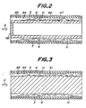
- Figs. 3 and 4 are sectional views of hollow-cylindrical SOFC, wherein various converting means are adopted instead of the hollow tube-shaped body.
- a solid pillar-shaped body 51 is placed in the central portion of the external space 45 instead of the hollow tube-shaped body.
- the pillar-shaped body 51 has the same outer profile in the radial directions as in the hollow tube-shaped body 47 of Fig. 1 and is supported by the metal felts 49 and 50 in the same manner as described above.
- a hollow tube-shaped body 52 is tapered and the outer diameters of the tapered tube-shaped body 52 are enlarged gradually and continuously from the upper-stream portion to the downstream portion of the fuel gas-flow.
- One opening of the hollow-cylindrical body 52 located in the upper-stream portion is sealed with a sealing portion 53.
- the other opening of the body 52 located in the downstream portion may be sealed with a sealing portion having a diameter larger than that of the sealing portion 53.
- the sectional area of the fuel gas-flow route 44 is relatively large in the upper-stream portion, and the sectional area becomes smaller gradually as the fuel gas flows toward the downstream portion. Therefore, the fuel gas flows into the fuel gas-flow route 44 as the arrow G and flows in the route relatively slowly in layers at first. However, as the fuel flow gas approaches to the downstream portion, the fuel are consumed and the fuel gas flows more rapidly to convert the fuel gas into the turbulent flows as shown by arrows H.
- converting means for example, hollow tube-shaped bodies or solid pillar-shaped bodies, in which many spines are provided on the outer surface or in which a channel or a convex is provided spirally on the outer surface like a screw, may be adopted other than ones shown in Figs. 1 to 4.
- the air electrode 5, etc. is formed on the surface of the porous support tube 1 or 41.
- a hollow-cylindrical air electrode itself or a hollow-cylindrical fuel electrode itself can be used as a rigid support without the above porous support tube 1 or 41.
- the SOFC element can be structurally independent without using the above porous support tube which does not constitute the electrodes.
- the other tube-shaped elements for example, tube-shaped elements in which their inner and outer profiles are tetragonal, hexagonal or the like taken in the radial directions, may be used.
Landscapes
- Life Sciences & Earth Sciences (AREA)
- Engineering & Computer Science (AREA)
- Manufacturing & Machinery (AREA)
- Sustainable Development (AREA)
- Sustainable Energy (AREA)
- Chemical & Material Sciences (AREA)
- Chemical Kinetics & Catalysis (AREA)
- Electrochemistry (AREA)
- General Chemical & Material Sciences (AREA)
- Fuel Cell (AREA)
Claims (8)
- Assemblage de piles à combustible présentant plusieurs piles à combustible d'oxyde solide tubulaires (1, 2, 3 , 4, 5) où un gaz choisi parmi le gaz oxydant et le gaz combustible passe dans un espace interne (12) de chaque pile à combustible et l'autre gaz passe dans des espaces externes entre lesdites piles, les électrodes (3,6) des dites piles voisines étant connectées électriquement les unes aux autres, caractérisé en ce que ledit assemblage comporte des corps allongés (47, 51, 52) dans lesdits espaces externes (45) et disposés dans la direction longitudinale des piles à combustible si bien qu'il existe des espaces étroits (44) pour l'écoulement du gaz entre lesdits corps allongés (47, 51, 52) et la surface des électrodes (3) exposée aux dits espaces externes si bien qu'il se produit un écoulement turbulent du gaz utilisé dans lesdits espaces étroits pour l'écoulement du gaz (44).
- Pile à combustible d'oxyde solide selon la revendication 1, dans laquelle chacun desdits corps allongés (47, 51, 52) est disposé dans une partie centrale de l'espace externe correspondant (45).
- Pile à combustible d'oxyde solide selon la revendication 2, dans laquelle ledit corps allongé (47, 51, 52) est un corps allongé massif ou un corps tubulaire avec au moins une ouverture scellée.
- Pile à combustible d'oxyde solide selon l'une quelconque des revendications 1 à 3, dans laquelle un feutre métallique (49, 50) est interposé entre les piles à combustible avoisinantes et les faces des espaces externes (45), et les corps allongés (47, 51, 52) sont en contacts avec le feutre métallique.
- Pile à combustible d'oxyde solide selon la revendication 4 dans laquelle, dans chacun desdits espaces externes, le profil extérieur dudit corps allongé (47, 51, 52), vu transversalement dans ladite direction longitudinale, est quadratique et à quatre lignes de bords disposées en direction longitudinale et quatre desdits feutres métalliques (49, 50) sont tournés vers l'espace externe et en contact avec les quatre lignes de bord dudit corps respectivement.
- Pile à combustible d'oxyde solide selon l'une quelconque des revendications 1 à 5 dans laquelle ledit corps allongé (47, 51, 52) est constitué de céramique électriquement non conductrice.
- Pile à combustible d'oxyde solide selon l'une quelconque des revendications 1 à 6 dans laquelle ledit corps allongé (47, 51, 52) est constitué d'un panneau de feutre formé de fibres céramiques.
- Pile à combustible d'oxyde solide selon l'une quelconque des revendications 1 à 7 dans laquelle ledit corps allongé (47, 51, 52) est conique et la dimension extérieure du corps conique augmente continuellement en direction aval de l'écoulement du gaz dans l'espace externe correspondant (45).
Applications Claiming Priority (4)
| Application Number | Priority Date | Filing Date | Title |
|---|---|---|---|
| JP32380/90 | 1990-02-15 | ||
| JP2032380A JPH03238760A (ja) | 1990-02-15 | 1990-02-15 | 固体電解質型燃料電池 |
| JP37151/90 | 1990-02-20 | ||
| JP2037151A JP2528989B2 (ja) | 1990-02-15 | 1990-02-20 | 固体電解質型燃料電池 |
Publications (2)
| Publication Number | Publication Date |
|---|---|
| EP0442742A1 EP0442742A1 (fr) | 1991-08-21 |
| EP0442742B1 true EP0442742B1 (fr) | 1995-05-03 |
Family
ID=26370941
Family Applications (1)
| Application Number | Title | Priority Date | Filing Date |
|---|---|---|---|
| EP91301210A Expired - Lifetime EP0442742B1 (fr) | 1990-02-15 | 1991-02-14 | Pile à combustible d'oxyde solide |
Country Status (5)
| Country | Link |
|---|---|
| US (1) | US5209989A (fr) |
| EP (1) | EP0442742B1 (fr) |
| JP (1) | JP2528989B2 (fr) |
| CA (1) | CA2036366C (fr) |
| DE (1) | DE69109336T2 (fr) |
Cited By (4)
| Publication number | Priority date | Publication date | Assignee | Title |
|---|---|---|---|---|
| US7416802B2 (en) | 2000-05-22 | 2008-08-26 | Acumentrics Corporation | Electrode-supported solid state electrochemical cell |
| WO2007100947A3 (fr) * | 2006-02-28 | 2009-09-11 | Motorola, Inc. | Dispositif à micro-pile à combustible intégrée |
| US8658327B2 (en) | 2002-02-20 | 2014-02-25 | Acumentrics Corporation | Fuel cell stacking and sealing |
| US9059450B2 (en) | 2008-10-28 | 2015-06-16 | Alan Devoe | Fuel cell device and system |
Families Citing this family (37)
| Publication number | Priority date | Publication date | Assignee | Title |
|---|---|---|---|---|
| US5750279A (en) * | 1992-02-28 | 1998-05-12 | Air Products And Chemicals, Inc. | Series planar design for solid electrolyte oxygen pump |
| DE4340486C1 (de) * | 1993-11-27 | 1995-06-01 | Forschungszentrum Juelich Gmbh | Brennstoffzelle und Verfahren zur Herstellung der Brennstoffzelle |
| AUPO617497A0 (en) | 1997-04-14 | 1997-05-08 | Jacobs, Ian Orde Michael | Injection moulding |
| US6074771A (en) * | 1998-02-06 | 2000-06-13 | Igr Enterprises, Inc. | Ceramic composite electrolytic device and method for manufacture thereof |
| DE19909930B4 (de) * | 1999-03-06 | 2004-09-02 | Fraunhofer-Gesellschaft zur Förderung der angewandten Forschung e.V. | Herstellung von tubulären PEM-Brennstoffzellen und Ionentauschermembranen |
| AUPQ278799A0 (en) | 1999-09-13 | 1999-10-07 | Telstra R & D Management Pty Ltd | An access control method |
| AUPQ315499A0 (en) * | 1999-09-29 | 1999-10-21 | Ceramic Fuel Cells Limited | Fuel cell assembly |
| AU780681B2 (en) * | 1999-09-29 | 2005-04-14 | Ceramic Fuel Cells Limited | Fuel cell assembly |
| CA2406312A1 (fr) * | 2000-04-18 | 2001-10-25 | Celltech Power, Inc. | Dispositif electrochimique et procedes de conversion d'energie |
| US7273671B2 (en) * | 2000-05-08 | 2007-09-25 | Honda Giken Kogyo Kabushiki Kaisha | Fuel cell and method for making the same |
| US6376117B1 (en) * | 2000-07-18 | 2002-04-23 | Sofco L.P. | Internal fuel staging for improved fuel cell performance |
| US6663997B2 (en) | 2000-12-22 | 2003-12-16 | Ballard Power Systems Inc. | Oxidant flow field for solid polymer electrolyte fuel cell |
| US7008709B2 (en) * | 2001-10-19 | 2006-03-07 | Delphi Technologies, Inc. | Fuel cell having optimized pattern of electric resistance |
| US6936367B2 (en) * | 2002-01-16 | 2005-08-30 | Alberta Research Council Inc. | Solid oxide fuel cell system |
| GB0201800D0 (en) * | 2002-01-26 | 2002-03-13 | Rolls Royce Plc | A fuel cell module |
| US7022429B2 (en) * | 2002-04-25 | 2006-04-04 | General Electric Company | Fluid passages for power generation equipment |
| US20040219418A1 (en) * | 2003-04-30 | 2004-11-04 | Peter Mardilovich | Fuel cell assembly and method for controlling reaction equilibrium |
| US7943270B2 (en) * | 2003-06-10 | 2011-05-17 | Celltech Power Llc | Electrochemical device configurations |
| JP4986376B2 (ja) * | 2003-11-26 | 2012-07-25 | 京セラ株式会社 | 燃料電池組立体 |
| US8153318B2 (en) | 2006-11-08 | 2012-04-10 | Alan Devoe | Method of making a fuel cell device |
| CN101346848B (zh) | 2005-11-08 | 2014-08-06 | A·德沃 | 包括具有热部分和冷部分的细长基体的固体氧化物燃料电池装置 |
| US8293415B2 (en) | 2006-05-11 | 2012-10-23 | Alan Devoe | Solid oxide fuel cell device and system |
| US20090029199A1 (en) * | 2007-05-02 | 2009-01-29 | Celltech Power Llc | Cathode Arrangements for Fuel Cells and Other Applications |
| US8278013B2 (en) * | 2007-05-10 | 2012-10-02 | Alan Devoe | Fuel cell device and system |
| US8227128B2 (en) | 2007-11-08 | 2012-07-24 | Alan Devoe | Fuel cell device and system |
| US20090145761A1 (en) * | 2007-12-11 | 2009-06-11 | Van Hassel Bart A | Oxygen separation element and method |
| US8343684B2 (en) | 2008-03-07 | 2013-01-01 | Alan Devoe | Fuel cell device and system |
| JP5495168B2 (ja) * | 2008-11-19 | 2014-05-21 | Toto株式会社 | 燃料電池モジュール |
| US9209474B2 (en) | 2009-03-06 | 2015-12-08 | Alan Devoe | Fuel cell device |
| CN102449839B (zh) * | 2009-05-28 | 2017-02-22 | 埃兹勒隆股份有限公司 | 氧化物陶瓷高温燃料电池 |
| DE102010002372A1 (de) * | 2010-02-26 | 2011-09-01 | Robert Bosch Gmbh | Brennstoffzellensystem mit verbesserter Kontaktierung der Elektroden |
| JP6219856B2 (ja) | 2012-02-24 | 2017-10-25 | アラン・デヴォー | 燃料電池デバイスを作製する方法 |
| US9023555B2 (en) | 2012-02-24 | 2015-05-05 | Alan Devoe | Method of making a fuel cell device |
| EP2980899B1 (fr) * | 2013-03-28 | 2018-04-25 | Kyocera Corporation | Cellule électrolytique à oxyde solide, dispositif à empilement de cellule et module électrolytique, et dispositif électrolytique |
| DE102015226740A1 (de) * | 2015-12-28 | 2017-06-29 | Robert Bosch Gmbh | Brennstoffzellenvorrichtung |
| DE102016202080A1 (de) * | 2016-02-11 | 2017-08-17 | Robert Bosch Gmbh | Brennstoffzellenvorrichtung |
| CN111224143B (zh) * | 2020-01-14 | 2021-03-16 | 西安交通大学 | 一种管式固体氧化物燃料电池结构 |
Family Cites Families (18)
| Publication number | Priority date | Publication date | Assignee | Title |
|---|---|---|---|---|
| US311504A (en) * | 1885-02-03 | Volney w | ||
| US3311504A (en) * | 1960-05-02 | 1967-03-28 | Leesona Corp | Fuel cell |
| US3147149A (en) * | 1961-02-27 | 1964-09-01 | Mc Graw Edison Co | Fuel cell construction |
| US3377203A (en) * | 1963-12-20 | 1968-04-09 | Univ Ernst Moritz Arndt | Method of producing fuel cells with solid electrolytes and ceramic oxide electrode layers |
| FR2182650B1 (fr) * | 1972-04-27 | 1974-07-26 | Citroen Sa | |
| FR2302598A1 (fr) * | 1975-02-25 | 1976-09-24 | Inst Francais Du Petrole | Pile a combustible dont les electrodes sont separees par des elements intercalaires |
| ZA814990B (en) * | 1980-12-22 | 1982-11-24 | Westinghouse Electric Corp | Fuel cell generator |
| US4331742A (en) * | 1980-12-24 | 1982-05-25 | Lovelace Alan M Administrator | Solid electrolyte cell |
| US4520082A (en) * | 1983-07-01 | 1985-05-28 | The United States Of America As Represented By The United States Department Of Energy | Fuel cell generator |
| US4664987A (en) * | 1984-11-15 | 1987-05-12 | Westinghouse Electric Corp. | Fuel cell arrangement |
| US4640875A (en) * | 1985-02-07 | 1987-02-03 | Westinghouse Electric Corp. | Fuel cell generator containing a gas sealing means |
| US4648945A (en) * | 1985-03-21 | 1987-03-10 | Westinghouse Electric Corp. | Bipolar plating of metal contacts onto oxide interconnection for solid oxide electrochemical cell |
| US4666798A (en) * | 1985-05-20 | 1987-05-19 | The United States Of America As Represented By The United States Department Of Energy | Serially connected solid oxide fuel cells having monolithic cores |
| US4812373A (en) * | 1986-04-16 | 1989-03-14 | Westinghouse Electric Corp. | Fuel feed arrangement for a fuel cell generator |
| US4664986A (en) * | 1986-04-16 | 1987-05-12 | Westinghouse Electric Corp. | High thermal conductivity gas feeder system |
| JPH0775170B2 (ja) * | 1986-05-21 | 1995-08-09 | 株式会社フジクラ | 固体電解質型燃料電池 |
| US4751152A (en) * | 1987-04-06 | 1988-06-14 | Westinghouse Electric Corp. | High bulk self-supporting electrode with integral gas feed conduit for solid oxide fuel cells |
| US4910100A (en) * | 1989-07-21 | 1990-03-20 | Fuji Electric Co., Ltd. | Solid electrolyte fuel cell |
-
1990
- 1990-02-20 JP JP2037151A patent/JP2528989B2/ja not_active Expired - Lifetime
-
1991
- 1991-02-11 US US07/653,283 patent/US5209989A/en not_active Expired - Fee Related
- 1991-02-14 CA CA002036366A patent/CA2036366C/fr not_active Expired - Fee Related
- 1991-02-14 EP EP91301210A patent/EP0442742B1/fr not_active Expired - Lifetime
- 1991-02-14 DE DE69109336T patent/DE69109336T2/de not_active Expired - Fee Related
Cited By (6)
| Publication number | Priority date | Publication date | Assignee | Title |
|---|---|---|---|---|
| US7416802B2 (en) | 2000-05-22 | 2008-08-26 | Acumentrics Corporation | Electrode-supported solid state electrochemical cell |
| US7659025B2 (en) | 2000-05-22 | 2010-02-09 | Acumentrics Corporation | Electrode-supported solid state electrochemical cell |
| US8658327B2 (en) | 2002-02-20 | 2014-02-25 | Acumentrics Corporation | Fuel cell stacking and sealing |
| WO2007100947A3 (fr) * | 2006-02-28 | 2009-09-11 | Motorola, Inc. | Dispositif à micro-pile à combustible intégrée |
| CN101617423B (zh) * | 2006-02-28 | 2012-11-28 | 摩托罗拉解决方案公司 | 集成微型燃料电池装置 |
| US9059450B2 (en) | 2008-10-28 | 2015-06-16 | Alan Devoe | Fuel cell device and system |
Also Published As
| Publication number | Publication date |
|---|---|
| CA2036366C (fr) | 1997-05-20 |
| EP0442742A1 (fr) | 1991-08-21 |
| JP2528989B2 (ja) | 1996-08-28 |
| DE69109336D1 (de) | 1995-06-08 |
| US5209989A (en) | 1993-05-11 |
| JPH03241670A (ja) | 1991-10-28 |
| DE69109336T2 (de) | 1996-01-25 |
| CA2036366A1 (fr) | 1991-08-16 |
Similar Documents
| Publication | Publication Date | Title |
|---|---|---|
| EP0442742B1 (fr) | Pile à combustible d'oxyde solide | |
| US5188910A (en) | Solid oxide fuel cells | |
| EP0505186B1 (fr) | Pile à combustible à électrolyte solide | |
| US5336569A (en) | Power generating equipment | |
| US7163759B2 (en) | Solid oxide fuel cell stack assembly having tapered diffusion layers | |
| EP0740358B1 (fr) | Unités de cellule pour piles à combustible à oxydes solides et générateur d'énergie utilisant ces unités de cellule | |
| US6953633B2 (en) | Fiber cooling of fuel cells | |
| JPS60100378A (ja) | 燃料電池 | |
| KR102905930B1 (ko) | 고체산화물 연료전지와 고체산화물 전해셀 | |
| JP2790666B2 (ja) | 燃料電池発電装置 | |
| JPH03238760A (ja) | 固体電解質型燃料電池 | |
| US7803493B2 (en) | Fuel cell system with separating structure bonded to electrolyte | |
| JP2698481B2 (ja) | 発電装置 | |
| JP2793275B2 (ja) | 燃料電池発電装置 | |
| US7632595B1 (en) | Compliant fuel cell system | |
| US20060292430A1 (en) | Fuel cell and fuel cell module therefor | |
| WO2026004449A1 (fr) | Empilement de cellules d'électrolyse à oxyde solide, module de cellule d'électrolyse, système de production d'hydrogène et procédé de fonctionnement d'un empilement de cellules d'électrolyse à oxyde solide | |
| KR20210116616A (ko) | 연료 전지 카트리지, 연료 전지 모듈 및 복합 발전 시스템 | |
| JPH02312166A (ja) | 固体電解質燃料電池の構造 |
Legal Events
| Date | Code | Title | Description |
|---|---|---|---|
| PUAI | Public reference made under article 153(3) epc to a published international application that has entered the european phase |
Free format text: ORIGINAL CODE: 0009012 |
|
| AK | Designated contracting states |
Kind code of ref document: A1 Designated state(s): BE DE FR GB |
|
| 17P | Request for examination filed |
Effective date: 19920211 |
|
| 17Q | First examination report despatched |
Effective date: 19930825 |
|
| GRAA | (expected) grant |
Free format text: ORIGINAL CODE: 0009210 |
|
| AK | Designated contracting states |
Kind code of ref document: B1 Designated state(s): BE DE FR GB |
|
| REF | Corresponds to: |
Ref document number: 69109336 Country of ref document: DE Date of ref document: 19950608 |
|
| ET | Fr: translation filed | ||
| PLBE | No opposition filed within time limit |
Free format text: ORIGINAL CODE: 0009261 |
|
| STAA | Information on the status of an ep patent application or granted ep patent |
Free format text: STATUS: NO OPPOSITION FILED WITHIN TIME LIMIT |
|
| 26N | No opposition filed | ||
| PGFP | Annual fee paid to national office [announced via postgrant information from national office to epo] |
Ref country code: GB Payment date: 19980204 Year of fee payment: 8 |
|
| PGFP | Annual fee paid to national office [announced via postgrant information from national office to epo] |
Ref country code: FR Payment date: 19980213 Year of fee payment: 8 |
|
| PGFP | Annual fee paid to national office [announced via postgrant information from national office to epo] |
Ref country code: DE Payment date: 19980217 Year of fee payment: 8 |
|
| PGFP | Annual fee paid to national office [announced via postgrant information from national office to epo] |
Ref country code: BE Payment date: 19980218 Year of fee payment: 8 |
|
| PG25 | Lapsed in a contracting state [announced via postgrant information from national office to epo] |
Ref country code: GB Free format text: LAPSE BECAUSE OF NON-PAYMENT OF DUE FEES Effective date: 19990214 |
|
| PG25 | Lapsed in a contracting state [announced via postgrant information from national office to epo] |
Ref country code: BE Free format text: LAPSE BECAUSE OF NON-PAYMENT OF DUE FEES Effective date: 19990228 |
|
| BERE | Be: lapsed |
Owner name: NGK INSULATORS LTD Effective date: 19990228 |
|
| GBPC | Gb: european patent ceased through non-payment of renewal fee |
Effective date: 19990214 |
|
| PG25 | Lapsed in a contracting state [announced via postgrant information from national office to epo] |
Ref country code: FR Free format text: LAPSE BECAUSE OF NON-PAYMENT OF DUE FEES Effective date: 19991029 |
|
| PG25 | Lapsed in a contracting state [announced via postgrant information from national office to epo] |
Ref country code: DE Free format text: LAPSE BECAUSE OF NON-PAYMENT OF DUE FEES Effective date: 19991201 |
|
| REG | Reference to a national code |
Ref country code: FR Ref legal event code: ST |