EP0442791A1 - Vorrichtung für den strahlungsdichten Durchgang einer flexiblen Zufuhrleitung durch die Schutzwandung einer heissen Zelle - Google Patents
Vorrichtung für den strahlungsdichten Durchgang einer flexiblen Zufuhrleitung durch die Schutzwandung einer heissen Zelle Download PDFInfo
- Publication number
- EP0442791A1 EP0442791A1 EP91400322A EP91400322A EP0442791A1 EP 0442791 A1 EP0442791 A1 EP 0442791A1 EP 91400322 A EP91400322 A EP 91400322A EP 91400322 A EP91400322 A EP 91400322A EP 0442791 A1 EP0442791 A1 EP 0442791A1
- Authority
- EP
- European Patent Office
- Prior art keywords
- flexible
- radiation
- olives
- sheath
- passage
- Prior art date
- Legal status (The legal status is an assumption and is not a legal conclusion. Google has not performed a legal analysis and makes no representation as to the accuracy of the status listed.)
- Granted
Links
- 230000005855 radiation Effects 0.000 claims abstract description 20
- 239000000463 material Substances 0.000 claims abstract description 17
- 230000004224 protection Effects 0.000 claims abstract description 16
- 241000207836 Olea <angiosperm> Species 0.000 claims description 29
- 239000007787 solid Substances 0.000 claims description 21
- 210000004907 gland Anatomy 0.000 claims description 6
- 239000012530 fluid Substances 0.000 claims description 4
- 238000009434 installation Methods 0.000 claims description 4
- 239000002245 particle Substances 0.000 claims description 4
- 239000011324 bead Substances 0.000 claims description 3
- 239000011358 absorbing material Substances 0.000 claims description 2
- 230000001678 irradiating effect Effects 0.000 claims description 2
- 239000011049 pearl Substances 0.000 abstract description 5
- 240000007817 Olea europaea Species 0.000 description 9
- 230000005670 electromagnetic radiation Effects 0.000 description 3
- 229910052751 metal Inorganic materials 0.000 description 3
- 239000002184 metal Substances 0.000 description 3
- 238000007789 sealing Methods 0.000 description 3
- 239000010959 steel Substances 0.000 description 3
- 229910000831 Steel Inorganic materials 0.000 description 2
- 239000011248 coating agent Substances 0.000 description 2
- 238000000576 coating method Methods 0.000 description 2
- 230000000295 complement effect Effects 0.000 description 2
- 239000000446 fuel Substances 0.000 description 2
- 230000006870 function Effects 0.000 description 2
- 238000002513 implantation Methods 0.000 description 2
- 230000002285 radioactive effect Effects 0.000 description 2
- 229910001018 Cast iron Inorganic materials 0.000 description 1
- 229910001208 Crucible steel Inorganic materials 0.000 description 1
- 241000287107 Passer Species 0.000 description 1
- 229920000297 Rayon Polymers 0.000 description 1
- 230000002745 absorbent Effects 0.000 description 1
- 239000002250 absorbent Substances 0.000 description 1
- 239000003831 antifriction material Substances 0.000 description 1
- 238000009835 boiling Methods 0.000 description 1
- 230000015556 catabolic process Effects 0.000 description 1
- 239000000356 contaminant Substances 0.000 description 1
- 238000006731 degradation reaction Methods 0.000 description 1
- 238000009826 distribution Methods 0.000 description 1
- 230000005484 gravity Effects 0.000 description 1
- 229910001385 heavy metal Inorganic materials 0.000 description 1
- 230000005865 ionizing radiation Effects 0.000 description 1
- 238000004519 manufacturing process Methods 0.000 description 1
- 238000000034 method Methods 0.000 description 1
- 230000001902 propagating effect Effects 0.000 description 1
- 230000001681 protective effect Effects 0.000 description 1
- 230000009993 protective function Effects 0.000 description 1
- 230000001869 rapid Effects 0.000 description 1
- 239000002964 rayon Substances 0.000 description 1
- 230000002787 reinforcement Effects 0.000 description 1
- 238000005728 strengthening Methods 0.000 description 1
- XLYOFNOQVPJJNP-UHFFFAOYSA-N water Substances O XLYOFNOQVPJJNP-UHFFFAOYSA-N 0.000 description 1
Images


Classifications
-
- G—PHYSICS
- G21—NUCLEAR PHYSICS; NUCLEAR ENGINEERING
- G21F—PROTECTION AGAINST X-RADIATION, GAMMA RADIATION, CORPUSCULAR RADIATION OR PARTICLE BOMBARDMENT; TREATING RADIOACTIVELY CONTAMINATED MATERIAL; DECONTAMINATION ARRANGEMENTS THEREFOR
- G21F7/00—Shielded cells or rooms
- G21F7/005—Shielded passages through walls; Locks; Transferring devices between rooms
Definitions
- the present invention relates to the field of biological protection with respect to ionizing and / or neutron radiation, as is the case for example in nuclear energy where enclosures, subjected to such radiation and called hot enclosures , are separated by a special concrete wall from the work area in which the staff work.
- these flexible supplies cross the protective wall in cylindrical conduits having a curved shape (called S-shaped crossings) or having a rectilinear shape (called straight crossings).
- the conduit consists of a curved (S-shaped crossing) or straight (straight crossing) metal tube embedded directly during the manufacturing process in the concrete wall itself.
- a plug is placed at each end of the duct, this plug being made of a material absorbing radiation (alpha and / or beta and / or gamma and / or neutron) and in this plug baffles have machined through which the flexible feed passes.
- the function of such caps is to ensure non-passage of radiation and contaminants from the cell and through the crossing.
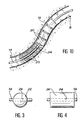
- FIG. 1 there is shown schematically in section, the concrete wall 2 which separates in a nuclear installation, the radioactive hot enclosure 4 from the work area 6 where the personnel work.
- the actual crossing of the wall is carried out by a curved conduit 8 hollowed out in the concrete and coated internally with a sheath 10 intended to protect the concrete from any mechanical degradation.
- the personnel protection is supplemented by a cast iron or steel plate 12 located on one of the faces of the wall 2. In this case, the sheath 8 obviously also passes through this metal plate 12.
- the sheath 10 which opens at one of its ends in the hot zone 4 and at the other end in the non-active zone 6 is therefore perfectly suitable for serving as a passage for any flexible supply such as cables or flexible tubes for conducting fluids, which thus makes it possible to supply the active zone 4, generally closed, in energy and in a certain number of fluids necessary for carrying out the operations which take place there.
- the sheath 10 does not contain materials capable of stopping radiation, the protective function against these is only ensured by its S shape which opposes the progression in a straight line of electromagnetic photons and also neutrons, thus that possibly by the plates 12 of suitable material embedded in the concrete wall.
- the calculation shows that to guarantee biological protection of an acceptable quality, one cannot exceed for the sheath 10 an internal diameter of the order of 35 mm, otherwise there is a risk of direct leaks, either by collimation of photons or neutrons on the wall of the sheath 10. Indeed, if theoretically, a photon appearing at the entry of the sheath 10 in cell 4 and propagating in a straight line cannot exceed point B marked in FIG. 1, it is not excluded that, by phenomena of subsequent successive reflections in C and D on the walls, according to paths marked in dotted lines in FIG. 1, certain photons nevertheless cross the entirety from the wall 2.
- the present invention specifically relates to a device for the radiation-tight passage of such a flexible supply through the biological protection wall of a hot enclosure which allows, while possibly increasing the diameter of the crossing sleeves beyond 35 mm, to maintain a total seal against radiation.
- This device for the passage, radiation-tight, of a flexible supply through the biological protection wall of a hot enclosure comprising a curved conduit, in particular of S shape, crossing the wall, coated with a sheath in radiation absorbing material and open to its two ends located respectively one in the hot zone and the other in the working zone, is characterized in that the flexible supply is provided, at least on a portion of the part corresponding to its path in the duct, solid removable parts, made of a radiation protection material compatible with the sheath material, said parts surround the flexible supply at least in place in the manner of the beads of a necklace and ensure both its setting in place by sliding in the conduit and the sealing of this curved conduit with respect to the rectilinear propagation of the photons of electromagnetic radiation which can be introduced therein.
- the main means of the invention consists of removable solid parts which are surrounded from place to place by the flexible supply which must pass through the duct, the location, the size and the material of which these different parts are made. being massive enough to completely block all possible paths for electromagnetic radiation.
- the massive parts which surround the flexible supply in its path inside the curved conduit in the manner in which pearls are threaded on a collar can take extremely varied forms as long as they fulfill the function assigned to them.
- these solid parts are spherical balls of diameter substantially equal to the internal diameter of the sheath and pierced along one of their diameters with a passage for flexible feeding.
- the solid parts are straight cylinders with a circular base of diameter substantially equal to the internal diameter of the sheath and pierced along their axis with a passage for flexible feeding.
- these solid parts are cylindrical olives in two integral parts and having, for the passage of the flexible supply, a conduit eccentric relative to the axis of the cylinder, so as to allow the helical mounting of the different olives around the flexible food.
- This method of fixing massive parts to the flexible supply allows, by virtue of the eccentric passage in the different successive parts, a helical distribution around the flexible supply of all of these same parts, which strengthens the seal. by further complicating the path for photons or neutrons which would nevertheless tend to introduce themselves into the curved duct and progress there.
- the massive pieces are no longer, as in the previous embodiments, distributed discreetly along the flexible supply, but on the contrary constitute a continuous flexible reinforcement all along the crossing thereof in the curved conduit.
- these massive pieces are cylindrical olives in two integral parts each having a concave spherical end face and a convex spherical end face of the same radius of curvature, so that the different successive olives fit one into the other in a swiveling manner and constitute a continuous flexible frame around the flexible supply.
- the material constituting the solid parts in each of the modes of implementation is chosen so as to have as good a coefficient of friction as possible on the material constituting the sheath which covers the interior of the curved duct.
- the skilled person will know in each particular case to choose the suitable materials among those which have a high capture section with respect to ionizing radiation.
- the invention also includes a cable gland traversed by power supply and closing at least one of the openings of the curved duct to improve protection against particulate radiation, such as in particular radiation alpha and beta.
- This cable gland which can be placed, preferably on the side of the clean area 6 for ease of access for personnel, can also be placed on the side of the contaminated cell 4, has the additional advantage of maintaining the supply flexible in place, since it passes through the cable gland.
- FIG. 2 a certain number of elements have been shown common with those of FIG. 1, designating them using the same number of references.
- the technical problem to be solved consists in passing the wall 2 through a flexible electric cable 14 which crosses the wall 2 via the curved conduit 8 and opens at 16 at the same time at the end of the latter into the hot zone 4 and at 18 by the other end of this same conduit 8 in the working area 6.
- a certain number of solid pieces or olives 20 which the cable crosses and whose external dimensions allow progression by sliding inside the sheath 10 coating the curved conduit 8.
- FIG. 2 to better illustrate the invention, the space between the outer surfaces of the olives and the sheath has been exaggerated. It is obvious that the smaller this space, the less radiation or particle leaks.
- the sheath 10 and the solid parts 20 can be made of a heavy metal such as lead which allows good sliding of the parts 20 in the sheath 10 while ensuring an almost total seal against electromagnetic radiation which could have tendency to enter the sheath 10 to pass through the wall 2.
- a heavy metal such as lead which allows good sliding of the parts 20 in the sheath 10 while ensuring an almost total seal against electromagnetic radiation which could have tendency to enter the sheath 10 to pass through the wall 2.
- any material which absorbs radiation and / or neutrons (as the case may be) and which has anti-friction properties is suitable for olives.
- This material can be homogeneous (lead) or heterogeneous (steel coated with an anti-friction material). It goes without saying that when there is a coating, it must resist ambient irradiation.
- the solid parts 20 which surround the electric cable 14 in place are removable, that is to say that they can be put in place around the cable 14 and removed at will when the need arises. actually feel it.
- the diameter of the sheath 10 no longer needs to be limited, as in the prior art, to a dimension of the order of 35 mm to achieve good sealing, and it is clear that this is simply the dimension of the solid parts 20 which, in connection with the diameter of the sheath 10, allows this sealing to be achieved.
- the curvature of the conduit 8 is such that the orifice 16 of the latter situated in the hot zone 4 is at a lower level of the orifice 18 of this same conduit 8 in the working zone 6.
- This arrangement is specially sought after and allows the introduction of the cable 14 provided with these massive pieces 20 by descent by gravity from the opening 18, a complementary traction of the latter from the active area 4 may nevertheless be necessary to ensure placing the assembly in the conduit 8.
- the solid pieces 20 behave in a way like the pearls of a necklace surrounding the flexible cable 14 and these same pearls can receive, within the framework of the invention, all the possible desirable shapes, and in particular a certain number of which will now be described below.
- FIG 3 there is shown an embodiment of the parts 20 which is one of the simplest since they consist in this example of balls 22 having a diametrical passage 24 for the cable or flexible frame 14 which passes through it .
- the solid part is a straight cylinder with a circular base 26 also having an axial passage channel 24 for the cable 14.
- FIG 5 there is shown another embodiment of the massive parts 20 which are produced in this case in the form of cylindrical olives 28 composed of two parts 28a and 28b which can be fixed to one another using any means known for this purpose, for example screws 30.
- a channel 24 for passing the cable 14, not shown is produced using two complementary and juxtaposable hollow half-cylinders 24a and 24b which, when secured using the screws 30 the two halves 28a and 28b of the olive 28 constitute a continuous circular cylindrical channel for the passage of the cable 14.
- this channel 24 which is its eccentricity by a distance e relative to the axis of the olive 28, which allows eccentricity of the cable 14 relative to the axis of the sheath, and, by successive mounting of the different olives 28 in a helix around this cable 14, as shown in FIG. 6, obtain an overall arrangement likely to reinforce the seal tee to the radiation of the curved duct 8.
- FIG. 6 provision has also been made for strengthening the protection against irradiating particles of small dimensions which arise in the hot enclosure 4, and which could pass through the crossing using two plugs.
- cable gland 32 and 34 located around the cable 14 in the openings of the conduit 8.
- dangerous radioactive radiation is not limited to only electromagnetic X or gamma photons but can also contain alpha and beta particles sometimes emitted with energy. important kinetics or neutrons.
- the cable glands 32 and 34 are sufficient to prevent them from accessing the conduit 8 and consequently the passage through the wall 2.
- the biological protection is further reinforced at the using two local absorbent metal plates surrounding the orifices of the curved channel 8 and which may for example be made of steel or lead.
- FIG. 6 there is shown diagrammatically in dashed lines a remote manipulator crossing the wall 2 and allowing, using a driving handle 40, remote manipulation by a driven clamp 41.
- FIG. 7 shows in the sheath 10, one of the olives 28 in FIG. 5 crossed by the cable 14 which we can clearly see, in this figure, that it is eccentric relative to the axis of the olive 28 and , consequently, relative to the axis of the sleeve 10.
- FIGS. 8 and 9 which correspond to sections AB and XY of the device of FIG. 6 make it possible to understand the helical mounting already explained of an olive 28 provided with its assembly screws 30 around the flexible cable 14. In fact, between FIG. 8 and FIG. 9 observe a 180 ° rotation of the olive 28 relative to the cable 14.
- FIG. 10 shows a particularly advantageous embodiment of the invention in which the various solid pieces or olives are strung contiguously. on the cable 14 and produce a sort of flexible frame passing through the sheath 10 which they completely fill thanks to their characteristics explained below.
- each of the olives or solid pieces 20 consists of a straight cylinder with a circular base pierced in its center with a channel 24 for the passage of the cable 14, and the ends of each of the olives 20 are made of spherical parts, alternately concave and convex, so that the different pearls 20 fit continuously and swiveling one inside the other to form a flexible frame which slides without difficulty at inside of the sheath 10 fitted to the walls of the curved duct 8.
Landscapes
- Physics & Mathematics (AREA)
- Engineering & Computer Science (AREA)
- General Engineering & Computer Science (AREA)
- High Energy & Nuclear Physics (AREA)
- Radiation-Therapy Devices (AREA)
- Particle Accelerators (AREA)
Applications Claiming Priority (2)
| Application Number | Priority Date | Filing Date | Title |
|---|---|---|---|
| FR9001676 | 1990-02-13 | ||
| FR9001676A FR2658264B1 (fr) | 1990-02-13 | 1990-02-13 | Dispositif pour le passage, etanche aux rayonnements, d'une alimentation souple au travers de la paroi de protection d'une enceinte chaude. |
Publications (2)
| Publication Number | Publication Date |
|---|---|
| EP0442791A1 true EP0442791A1 (de) | 1991-08-21 |
| EP0442791B1 EP0442791B1 (de) | 1994-06-22 |
Family
ID=9393650
Family Applications (1)
| Application Number | Title | Priority Date | Filing Date |
|---|---|---|---|
| EP19910400322 Expired - Lifetime EP0442791B1 (de) | 1990-02-13 | 1991-02-11 | Vorrichtung für den strahlungsdichten Durchgang einer flexiblen Zufuhrleitung durch die Schutzwandung einer heissen Zelle |
Country Status (4)
| Country | Link |
|---|---|
| EP (1) | EP0442791B1 (de) |
| JP (1) | JP2961668B2 (de) |
| DE (1) | DE69102554T2 (de) |
| FR (1) | FR2658264B1 (de) |
Cited By (1)
| Publication number | Priority date | Publication date | Assignee | Title |
|---|---|---|---|---|
| FR3120735A1 (fr) * | 2021-03-15 | 2022-09-16 | Lemer Pax | traversée de ventilation pour une paroi radio-protectrice et la paroi radio-protectrice équipée |
Citations (4)
| Publication number | Priority date | Publication date | Assignee | Title |
|---|---|---|---|---|
| FR1501888A (fr) * | 1966-09-27 | 1967-11-18 | Commissariat Energie Atomique | Perfectionnements aux systèmes pour assurer l'étanchéité de dispositifs filiformes, tels que des sondes, à introduire dans des enceintes sous pression |
| US4334729A (en) * | 1980-02-11 | 1982-06-15 | Kortech Engineering, Inc. | Penetrator assembly |
| EP0139337A2 (de) * | 1983-10-19 | 1985-05-02 | Pidou B.V. | Mehrteiliges Dichtungssystem |
| EP0318019A1 (de) * | 1987-11-27 | 1989-05-31 | RXS Schrumpftechnik-Garnituren GmbH | Vorrichtung zur wasser- und gasdichten Durchführung von langgestreckten Gegenständen durch Bauwerkswände |
-
1990
- 1990-02-13 FR FR9001676A patent/FR2658264B1/fr not_active Expired - Fee Related
-
1991
- 1991-02-11 EP EP19910400322 patent/EP0442791B1/de not_active Expired - Lifetime
- 1991-02-11 DE DE1991602554 patent/DE69102554T2/de not_active Expired - Fee Related
- 1991-02-12 JP JP3039007A patent/JP2961668B2/ja not_active Expired - Lifetime
Patent Citations (4)
| Publication number | Priority date | Publication date | Assignee | Title |
|---|---|---|---|---|
| FR1501888A (fr) * | 1966-09-27 | 1967-11-18 | Commissariat Energie Atomique | Perfectionnements aux systèmes pour assurer l'étanchéité de dispositifs filiformes, tels que des sondes, à introduire dans des enceintes sous pression |
| US4334729A (en) * | 1980-02-11 | 1982-06-15 | Kortech Engineering, Inc. | Penetrator assembly |
| EP0139337A2 (de) * | 1983-10-19 | 1985-05-02 | Pidou B.V. | Mehrteiliges Dichtungssystem |
| EP0318019A1 (de) * | 1987-11-27 | 1989-05-31 | RXS Schrumpftechnik-Garnituren GmbH | Vorrichtung zur wasser- und gasdichten Durchführung von langgestreckten Gegenständen durch Bauwerkswände |
Cited By (2)
| Publication number | Priority date | Publication date | Assignee | Title |
|---|---|---|---|---|
| FR3120735A1 (fr) * | 2021-03-15 | 2022-09-16 | Lemer Pax | traversée de ventilation pour une paroi radio-protectrice et la paroi radio-protectrice équipée |
| WO2022194753A1 (fr) * | 2021-03-15 | 2022-09-22 | Lemer Pax | Traversée de ventilation pour une paroi radio-protectrice et la paroi radio-protectrice équipée |
Also Published As
| Publication number | Publication date |
|---|---|
| JPH06138291A (ja) | 1994-05-20 |
| JP2961668B2 (ja) | 1999-10-12 |
| DE69102554T2 (de) | 1995-02-02 |
| FR2658264B1 (fr) | 1992-04-30 |
| DE69102554D1 (de) | 1994-07-28 |
| FR2658264A1 (fr) | 1991-08-16 |
| EP0442791B1 (de) | 1994-06-22 |
Similar Documents
| Publication | Publication Date | Title |
|---|---|---|
| CA2101797C (fr) | Procede et appareil pour le traitement de lesions par rayonnement a haute energie | |
| EP0057634B1 (de) | Abgedichtete Laserstrahl-Durchführung durch die Wand einer heissen Zelle und Verfahren Verwendungsverfahren | |
| EP0442791B1 (de) | Vorrichtung für den strahlungsdichten Durchgang einer flexiblen Zufuhrleitung durch die Schutzwandung einer heissen Zelle | |
| EP0995345B1 (de) | Vorrichtung zur anregung eines gases durch oberflächenwellenplasma | |
| BE1013025A3 (fr) | Dispositif d'application d'un revetement sur un substrat. | |
| EP0076748B1 (de) | Kernreaktor-Brennstoffbündel | |
| FR2715762A1 (fr) | Dispositif de fixation du fond d'un conteneur de transport et/ou stockage de matières radioactives. | |
| FR2672459A1 (fr) | Dispositif de rechargement par plasma a orifice oblique. | |
| EP0570286B1 (de) | Hebevorrichtung mittels eines Kabels für die Handhabung schwerer Lasten im Inneren eines dichten, gepanzerten Gehäuses | |
| FR3063812A1 (fr) | Dispositif d'ecran aux rayonnements ionisants | |
| EP0173602B1 (de) | Notwärmetauscher zur Kühlung des Primärmittels eines Kernreaktors und Verfahren zu dessen Zusammenbau | |
| EP0212171B1 (de) | Schutzhülle für Kernreaktor mit kontrollierter Kernfusion in einem Plasma, sowie Verfahren zur Herstellung einer solchen Schutzhülle | |
| FR2705047A1 (fr) | Procédé et dispositif de soudage par faisceau d'électrons de deux pièces d'un composant de grande dimension et notamment d'un générateur de vapeur d'un réacteur nucléaire à eau sous pression. | |
| EP0349379A1 (de) | Regelspinne mit demortierbaren Stäben für ein Kernbrennstabbündel | |
| FR2610136A1 (fr) | Dispositif de refroidissement d'un reacteur a fusion thermonucleaire et bloc modulaire de garnissage pour la realisation d'une paroi d'un tel dispositif | |
| EP0752150A1 (de) | Einen schmiedestahlkörper mit einem nichtkreisförmigen schnitt enthaltende kernbrennstoffelementverpackung | |
| FR2616000A1 (fr) | Dispositif permettant la coulee de verre radioactif en fusion dans un conteneur | |
| FR2547099A1 (fr) | Dispositif de couverture de reacteur a fusion nucleaire utilisant la reaction deuterium, tritium, a materiau tritigene | |
| EP0374060A1 (de) | Vorrichtung im Vakuum grossen Volumens und Verfahren zu seiner Herstellung | |
| EP0512886A1 (de) | Vorrichtung zur Primärkühlmitteltemperaturmessung eines Kernreaktors mit beschleunigter inerer Strömung | |
| BE1012412A3 (fr) | Assemblage de combustible pour un reacteur nucleaire refroidi par de l'eau. | |
| EP0090743B1 (de) | Schutzvorrichtung gegen Wärme und Radiation für einen in einem Kernreaktorbehälter eingetauchten Wärmeübertrager | |
| WO2022269142A1 (fr) | Enceinte et procédé de protection contre des rayonnements externes | |
| EP0449713A1 (de) | Ladekorb mit integrierter Gaskühlung für ein aus der Spaltzone eines Kernreaktors entnommenen Brennstabbündels | |
| FR2563040A1 (fr) | Bouchon-couvercle du coeur d'un reacteur nucleaire |
Legal Events
| Date | Code | Title | Description |
|---|---|---|---|
| PUAI | Public reference made under article 153(3) epc to a published international application that has entered the european phase |
Free format text: ORIGINAL CODE: 0009012 |
|
| AK | Designated contracting states |
Kind code of ref document: A1 Designated state(s): DE GB |
|
| 17P | Request for examination filed |
Effective date: 19910928 |
|
| 17Q | First examination report despatched |
Effective date: 19931115 |
|
| GRAA | (expected) grant |
Free format text: ORIGINAL CODE: 0009210 |
|
| AK | Designated contracting states |
Kind code of ref document: B1 Designated state(s): DE GB |
|
| REF | Corresponds to: |
Ref document number: 69102554 Country of ref document: DE Date of ref document: 19940728 |
|
| GBT | Gb: translation of ep patent filed (gb section 77(6)(a)/1977) |
Effective date: 19940701 |
|
| PLBE | No opposition filed within time limit |
Free format text: ORIGINAL CODE: 0009261 |
|
| STAA | Information on the status of an ep patent application or granted ep patent |
Free format text: STATUS: NO OPPOSITION FILED WITHIN TIME LIMIT |
|
| 26N | No opposition filed | ||
| PGFP | Annual fee paid to national office [announced via postgrant information from national office to epo] |
Ref country code: DE Payment date: 20000302 Year of fee payment: 10 |
|
| PGFP | Annual fee paid to national office [announced via postgrant information from national office to epo] |
Ref country code: GB Payment date: 20010207 Year of fee payment: 11 |
|
| PG25 | Lapsed in a contracting state [announced via postgrant information from national office to epo] |
Ref country code: DE Free format text: LAPSE BECAUSE OF NON-PAYMENT OF DUE FEES Effective date: 20011201 |
|
| REG | Reference to a national code |
Ref country code: GB Ref legal event code: IF02 |
|
| PG25 | Lapsed in a contracting state [announced via postgrant information from national office to epo] |
Ref country code: GB Free format text: LAPSE BECAUSE OF NON-PAYMENT OF DUE FEES Effective date: 20020211 |
|
| GBPC | Gb: european patent ceased through non-payment of renewal fee |
Effective date: 20020211 |