EP0442828A1 - Fernbedienungsvorrichtung eines Trenners oder anderen elektrischen Schalters in einem Tunnel - Google Patents
Fernbedienungsvorrichtung eines Trenners oder anderen elektrischen Schalters in einem Tunnel Download PDFInfo
- Publication number
- EP0442828A1 EP0442828A1 EP91420041A EP91420041A EP0442828A1 EP 0442828 A1 EP0442828 A1 EP 0442828A1 EP 91420041 A EP91420041 A EP 91420041A EP 91420041 A EP91420041 A EP 91420041A EP 0442828 A1 EP0442828 A1 EP 0442828A1
- Authority
- EP
- European Patent Office
- Prior art keywords
- tunnel
- disconnector
- movement
- control station
- switch
- Prior art date
- Legal status (The legal status is an assumption and is not a legal conclusion. Google has not performed a legal analysis and makes no representation as to the accuracy of the status listed.)
- Withdrawn
Links
- 230000005540 biological transmission Effects 0.000 claims abstract description 12
- 230000009347 mechanical transmission Effects 0.000 claims description 3
- 229920000297 Rayon Polymers 0.000 description 1
- 239000012530 fluid Substances 0.000 description 1
- 239000002964 rayon Substances 0.000 description 1
- 230000001131 transforming effect Effects 0.000 description 1
Images
Classifications
-
- H—ELECTRICITY
- H01—ELECTRIC ELEMENTS
- H01H—ELECTRIC SWITCHES; RELAYS; SELECTORS; EMERGENCY PROTECTIVE DEVICES
- H01H3/00—Mechanisms for operating contacts
- H01H3/32—Driving mechanisms, i.e. for transmitting driving force to the contacts
- H01H3/46—Driving mechanisms, i.e. for transmitting driving force to the contacts using rod or lever linkage, e.g. toggle
-
- B—PERFORMING OPERATIONS; TRANSPORTING
- B60—VEHICLES IN GENERAL
- B60M—POWER SUPPLY LINES, AND DEVICES ALONG RAILS, FOR ELECTRICALLY- PROPELLED VEHICLES
- B60M1/00—Power supply lines for contact with collector on vehicle
- B60M1/12—Trolley lines; Accessories therefor
- B60M1/18—Section insulators; Section switches
Definitions
- the present invention relates to a device for the remote operation of a disconnector, or other electrical switch, placed high up and on the internal wall of a tunnel with circular section, that is to say of a tunnel with section in shape of a circle or portion of a circle, and in particular of a railway tunnel of this type.
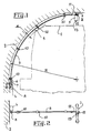
- FIG. 1 shows, in partial section, a portion of a railway tunnel of which, as will be the case for the future tunnel under the channel, for example, the section is strictly circular. In this case, it is a tunnel whose radius R is of the order of four meters, and for which the gauge 1 of the train arrives at a distance e from the internal wall 2 which is of the order d 'only about twenty centimeters.
- this one is equipped with disconnectors 3 which are arranged at the top, that is to say at the top of the circular internal wall 2.
- each of these disconnectors 3 which must be directly accessible to operators, is then necessarily located at the bottom and on the side of the tunnel, as shown in FIG. 1, so that the problem of transmission arises. mechanics of the opening and closing movement of the disconnector 3 between this box 4 placed at the bottom and on the side of the tunnel, and this disconnector 3 which is placed at the top of the latter.
- manual control must be provided at the level of the housing 4, in order to be able to actuate the disconnector 3 in the event of a power failure.
- the movement transmission link between the housing 4 and the disconnector 3 is mechanical, and is not for example a link by electromagnetic waves.
- a first solution that comes immediately to mind is to use, to achieve a mechanical transmission in an arc of a circle running along the wall 2 without leaving the space 5 of width e, a series of short rods articulated one on the another, the joints being themselves each fixed to the wall 2 by means of an articulated link.
- This is a solution conventionally used for the control of disconnectors but which in this case would require a large number of short rods, six to eight for example, which would require a large number of bearings and a number of important adjustments: this solution would therefore be excessively complex and expensive.
- a last solution borrowed from the known art would be to use a torsional transmission generated by the axial rotation of a flexible or semi-rigid rod or cable, like the devices for example used for drills.
- a device would in fact be either extremely expensive in the case of a semi-rigid rod conventionally rotating in ball paths, or difficult to implement in the case of the rotary cable, because, given the particularly large transmission distance which it is a question of making a large number of turns at the bottom to hope for a quarter-turn rotation of the disconnector at the top of the tunnel.
- the object of the invention is to propose a new solution which does not have all of these drawbacks.
- a device for maneuvering at a distance from a disconnector, or other electrical switch, placed at a height and on the internal wall of a tunnel with circular section this maneuver being carried out from a control placed, in the same section as the disconnector, at the bottom and on the side of the tunnel, and only a limited space, running along the wall, being available to ensure mechanical transmission of movement between this control station and this disconnector
- this device using, to achieve this transmission of movement, a rigid rod in an arc of a circle of substantially the same radius of curvature as the tunnel, ensuring the major part of the connection between the control station and the disconnector and able to move in this restricted space in one direction as in the other along the circumference of this section of the tunnel over an angular distance sufficient to drive, by a conventional device, of the rod-crank type for example, associated with the disconnector, the opening or closing of this disconnector.
- FIG. 4 shows how this tensile movement translates for a movement towards the left of the upper end of the rod in a quarter circle 9, which causes, by rotation of the axis 13, the opening of the disconnector 3.
- the electrical member to be actuated could not be a disconnector, but for example a circuit breaker, a switch able - unlike a disconnector - to be actuated under load, a switch two or more ways, etc ...
Landscapes
- Engineering & Computer Science (AREA)
- Mechanical Engineering (AREA)
- Mechanisms For Operating Contacts (AREA)
Applications Claiming Priority (2)
| Application Number | Priority Date | Filing Date | Title |
|---|---|---|---|
| FR9001935 | 1990-02-13 | ||
| FR9001935A FR2658357B1 (fr) | 1990-02-13 | 1990-02-13 | Dispositif de manóoeuvre a distance d'un sectionneur, ou autre commutateur electrique, place dans un tunnel. |
Publications (1)
| Publication Number | Publication Date |
|---|---|
| EP0442828A1 true EP0442828A1 (de) | 1991-08-21 |
Family
ID=9393837
Family Applications (1)
| Application Number | Title | Priority Date | Filing Date |
|---|---|---|---|
| EP91420041A Withdrawn EP0442828A1 (de) | 1990-02-13 | 1991-02-06 | Fernbedienungsvorrichtung eines Trenners oder anderen elektrischen Schalters in einem Tunnel |
Country Status (2)
| Country | Link |
|---|---|
| EP (1) | EP0442828A1 (de) |
| FR (1) | FR2658357B1 (de) |
Cited By (1)
| Publication number | Priority date | Publication date | Assignee | Title |
|---|---|---|---|---|
| CN111391721A (zh) * | 2020-04-16 | 2020-07-10 | 中铁二院工程集团有限责任公司 | 一种用于铁路隧道内疏散救援的接触网结构 |
Citations (3)
| Publication number | Priority date | Publication date | Assignee | Title |
|---|---|---|---|---|
| DE397538C (de) * | 1923-01-09 | 1924-07-04 | Ver Isolatorenwerke Akt Ges | Vorrichtung zur Trennung von Streckenabschnitten der Fahrleitung elektrischer Bahnen |
| US3647996A (en) * | 1971-01-07 | 1972-03-07 | S & C Electric Co | Polyphase disconnecting switch for high-voltage circuit having a conductor at each apex of a triangle |
| EP0403374A1 (de) * | 1989-06-14 | 1990-12-19 | Spie-Batignolles | Trennvorrichtung für einen Tunnel-Fahrdraht |
-
1990
- 1990-02-13 FR FR9001935A patent/FR2658357B1/fr not_active Expired - Fee Related
-
1991
- 1991-02-06 EP EP91420041A patent/EP0442828A1/de not_active Withdrawn
Patent Citations (3)
| Publication number | Priority date | Publication date | Assignee | Title |
|---|---|---|---|---|
| DE397538C (de) * | 1923-01-09 | 1924-07-04 | Ver Isolatorenwerke Akt Ges | Vorrichtung zur Trennung von Streckenabschnitten der Fahrleitung elektrischer Bahnen |
| US3647996A (en) * | 1971-01-07 | 1972-03-07 | S & C Electric Co | Polyphase disconnecting switch for high-voltage circuit having a conductor at each apex of a triangle |
| EP0403374A1 (de) * | 1989-06-14 | 1990-12-19 | Spie-Batignolles | Trennvorrichtung für einen Tunnel-Fahrdraht |
Cited By (2)
| Publication number | Priority date | Publication date | Assignee | Title |
|---|---|---|---|---|
| CN111391721A (zh) * | 2020-04-16 | 2020-07-10 | 中铁二院工程集团有限责任公司 | 一种用于铁路隧道内疏散救援的接触网结构 |
| CN111391721B (zh) * | 2020-04-16 | 2022-09-16 | 中铁二院工程集团有限责任公司 | 一种用于铁路隧道内疏散救援的接触网结构 |
Also Published As
| Publication number | Publication date |
|---|---|
| FR2658357B1 (fr) | 1992-05-07 |
| FR2658357A1 (fr) | 1991-08-16 |
Similar Documents
| Publication | Publication Date | Title |
|---|---|---|
| EP2575155B1 (de) | Gerät zur verteilung von strom mittlerer spannung | |
| EP0627527A1 (de) | Anlage zum Tragen von Strassenmobilär, senkbar mit elektronische Antriebsmitteln | |
| FR2672532A1 (fr) | Chariot automoteur equipe d'un robot. | |
| FR2638813A1 (fr) | Vehicule autopropulse pour meulage de tuyauterie | |
| CA2898389A1 (fr) | Appareillage electrique a double mouvement de contacts comportant un dispositif de renvoi a deux leviers | |
| EP0693763B1 (de) | Mittelspannung elektrischer Schalter | |
| EP2513934B1 (de) | Gasisoliertes, metallgekapseltes hoch- oder mittelspannungsschaltgerät mit einer drehenden betätigungswelle und einem dadurch beweglichen kontakt mit verbesserter montage, anwendung an dreiphasige schaltanlagen | |
| FR2790592A1 (fr) | Disjoncteur haute tension a double mouvement | |
| EP2926353B1 (de) | Federartige steuerungsvorrichtung, insbesondere für hochspannungsschaltungs- oder mittelspannungsschutzschalter oder -schalter | |
| EP2605264A1 (de) | Betätigungseinrichtung eines Hilfskontaktes in einer elektrischen Schaltvorrichtung | |
| FR2865572A1 (fr) | Dispositif de commande de dispositif de coupure d'energie electrique | |
| FR2744284A1 (fr) | Interrupteur ou disjoncteur multipolaire moyenne tension | |
| EP2178100B1 (de) | Elektrisches Schaltgerät, das mit zwei Schaltern ausgerüstet ist, wie etwa einem Sammelschienentrennschalter und einem Erdungstrenner, einschließlich der gemeinsamen Antriebsmittel der mobilen Kontakte der Schalter | |
| FR2658357A1 (fr) | Dispositif de manóoeuvre a distance d'un sectionneur, ou autre commutateur electrique, place dans un tunnel. | |
| EP2144261B1 (de) | Absperrvorrichtung zum Trennen oder Verbinden von zwei Teilen eines elektrischen Schaltkreises, von denen einer ein Spannungstransformator ist | |
| WO2011135034A1 (fr) | Sectionneur de terre a encombrement reduit | |
| EP0320416B1 (de) | Drehbarer Kollektor zur Speisung eines Motors von Stoffaufwickelvorrichtungen oder von anderen Abschliessvorrichtungen mit integrierter Notfunktion | |
| EP0592338B1 (de) | Mechanismus für einen Erdungsschalter | |
| EP4179610A1 (de) | Getriebemotor mit einem zylindergehäuse und entsprechender rohrmotor | |
| EP2023361B1 (de) | Schaltvorrichtung vom Dreiphasentyp unter Metallmantel zur Abgrenzung und mit reduzierten Übertragungskräften pro Phase | |
| EP0035604B1 (de) | Sicherheitsvorrichtung für Laststufenschalter | |
| FR2726120A1 (fr) | Mecanisme de commande pour un dispositif de commutation | |
| FR2675944A1 (fr) | Dispositif de coupure d'exterieur pour ligne electrique. | |
| FR2551914A1 (fr) | Auxiliaire de telecommande pour enclenchement a distance d'un disjoncteur a prehenseur d'enclenchement et de declenchement | |
| CH555136A (de) | Canne a peche a moulinet. |
Legal Events
| Date | Code | Title | Description |
|---|---|---|---|
| PUAI | Public reference made under article 153(3) epc to a published international application that has entered the european phase |
Free format text: ORIGINAL CODE: 0009012 |
|
| AK | Designated contracting states |
Kind code of ref document: A1 Designated state(s): DK GB SE |
|
| 17P | Request for examination filed |
Effective date: 19911011 |
|
| 17Q | First examination report despatched |
Effective date: 19931027 |
|
| STAA | Information on the status of an ep patent application or granted ep patent |
Free format text: STATUS: THE APPLICATION IS DEEMED TO BE WITHDRAWN |
|
| 18D | Application deemed to be withdrawn |
Effective date: 19940722 |