EP0442849B1 - Méthode d'utilisation et régénération de résines anioniques dans des systèmes d'eau à contre-courant de solutions tinctoriales et analogues - Google Patents
Méthode d'utilisation et régénération de résines anioniques dans des systèmes d'eau à contre-courant de solutions tinctoriales et analogues Download PDFInfo
- Publication number
- EP0442849B1 EP0442849B1 EP91830005A EP91830005A EP0442849B1 EP 0442849 B1 EP0442849 B1 EP 0442849B1 EP 91830005 A EP91830005 A EP 91830005A EP 91830005 A EP91830005 A EP 91830005A EP 0442849 B1 EP0442849 B1 EP 0442849B1
- Authority
- EP
- European Patent Office
- Prior art keywords
- column
- treatment
- nacl solution
- counter
- current
- Prior art date
- Legal status (The legal status is an assumption and is not a legal conclusion. Google has not performed a legal analysis and makes no representation as to the accuracy of the status listed.)
- Expired - Lifetime
Links
- XLYOFNOQVPJJNP-UHFFFAOYSA-N water Substances O XLYOFNOQVPJJNP-UHFFFAOYSA-N 0.000 title claims abstract description 29
- 239000011347 resin Substances 0.000 title claims abstract description 19
- 229920005989 resin Polymers 0.000 title claims abstract description 19
- 238000000034 method Methods 0.000 title claims abstract description 12
- 238000010992 reflux Methods 0.000 title claims abstract description 8
- 230000008929 regeneration Effects 0.000 title claims abstract description 8
- 238000011069 regeneration method Methods 0.000 title claims abstract description 8
- 125000000129 anionic group Chemical group 0.000 title abstract description 3
- FAPWRFPIFSIZLT-UHFFFAOYSA-M Sodium chloride Chemical compound [Na+].[Cl-] FAPWRFPIFSIZLT-UHFFFAOYSA-M 0.000 claims abstract description 42
- 238000011282 treatment Methods 0.000 claims abstract description 28
- 239000011780 sodium chloride Substances 0.000 claims abstract description 21
- 230000005587 bubbling Effects 0.000 claims abstract description 5
- HEMHJVSKTPXQMS-UHFFFAOYSA-M Sodium hydroxide Chemical compound [OH-].[Na+] HEMHJVSKTPXQMS-UHFFFAOYSA-M 0.000 claims description 21
- 238000005406 washing Methods 0.000 claims description 14
- 239000003957 anion exchange resin Substances 0.000 claims description 3
- 108091006629 SLC13A2 Proteins 0.000 description 10
- 238000010586 diagram Methods 0.000 description 5
- 230000001172 regenerating effect Effects 0.000 description 5
- 239000000203 mixture Substances 0.000 description 4
- 239000002253 acid Substances 0.000 description 3
- 239000002245 particle Substances 0.000 description 3
- 239000004094 surface-active agent Substances 0.000 description 3
- MYRTYDVEIRVNKP-UHFFFAOYSA-N 1,2-Divinylbenzene Chemical compound C=CC1=CC=CC=C1C=C MYRTYDVEIRVNKP-UHFFFAOYSA-N 0.000 description 2
- VEXZGXHMUGYJMC-UHFFFAOYSA-N Hydrochloric acid Chemical compound Cl VEXZGXHMUGYJMC-UHFFFAOYSA-N 0.000 description 2
- 229920002536 Scavenger resin Polymers 0.000 description 2
- 238000010521 absorption reaction Methods 0.000 description 2
- 239000000975 dye Substances 0.000 description 2
- 230000008030 elimination Effects 0.000 description 2
- 238000003379 elimination reaction Methods 0.000 description 2
- 238000001914 filtration Methods 0.000 description 2
- 239000004793 Polystyrene Substances 0.000 description 1
- 238000004132 cross linking Methods 0.000 description 1
- 230000001419 dependent effect Effects 0.000 description 1
- 239000003456 ion exchange resin Substances 0.000 description 1
- 229920003303 ion-exchange polymer Polymers 0.000 description 1
- 239000007788 liquid Substances 0.000 description 1
- 230000014759 maintenance of location Effects 0.000 description 1
- 238000002156 mixing Methods 0.000 description 1
- 150000002823 nitrates Chemical class 0.000 description 1
- 150000002826 nitrites Chemical class 0.000 description 1
- 229920000642 polymer Polymers 0.000 description 1
- 229920002223 polystyrene Polymers 0.000 description 1
- 239000011148 porous material Substances 0.000 description 1
- 238000005086 pumping Methods 0.000 description 1
- 239000011044 quartzite Substances 0.000 description 1
- 238000004064 recycling Methods 0.000 description 1
- 239000012492 regenerant Substances 0.000 description 1
- 230000008439 repair process Effects 0.000 description 1
- 230000000630 rising effect Effects 0.000 description 1
- 239000000126 substance Substances 0.000 description 1
- 239000002351 wastewater Substances 0.000 description 1
- 239000003643 water by type Substances 0.000 description 1
Images


Classifications
-
- B—PERFORMING OPERATIONS; TRANSPORTING
- B01—PHYSICAL OR CHEMICAL PROCESSES OR APPARATUS IN GENERAL
- B01J—CHEMICAL OR PHYSICAL PROCESSES, e.g. CATALYSIS OR COLLOID CHEMISTRY; THEIR RELEVANT APPARATUS
- B01J49/00—Regeneration or reactivation of ion-exchangers; Apparatus therefor
- B01J49/05—Regeneration or reactivation of ion-exchangers; Apparatus therefor of fixed beds
- B01J49/07—Regeneration or reactivation of ion-exchangers; Apparatus therefor of fixed beds containing anionic exchangers
Definitions
- the subject of the invention is a method for regeneration of anion exchange resins in reflux water treatment systems, which characteristically is used in the treatment of refluxes, and especially those from dye-works and in which the resins to be regenerated are treated with an alkalised NaCl solution.
- anion exchange resins for retention of organic molecules by absorption on the pore structure.
- Such resins are usually called scavenger resins.
- these resins are the Purolite A-500 and A-500P strong base, macroporous exchange resins.
- regeneration of the scavenger resins can be obtained by treating it with a solution of NaCl duly alkalised with NaOH, as disclosed, e.g. in the Purolite, A-500 ion exchange resins data sheet, issued by Purolite International Limited, Wales.
- the object of the invention is to provide a more efficient regenerative method.
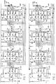
- Figs. 1 to 12 provide a diagram of the system, in which the various phases of the active circuits are indicated.
- 1 shows the arrival of the water to be treated
- 3 shows the softened hot water feed at about 30-40°C
- 5 shows the feed line for hydrochloric acid HC1 generally about 33%
- 7 shows the sodium hydroxide feed generally about 30%
- 9 shows the feed for a sodium chloride NaC1 solution at about 24%.
- the various feed pipes 1, 3, 5, 7 and 9 are connected to the various columns of a system, which in the diagram is of the four column type.
- the first column, 12, is a filtering column, generally of quartzite type; columns 14, 16 and 18 are resin filtering columns, generally of anionic resin types, for removal of nitrites and nitrates and other substances, and these resins must be regenerated.
- the resins may be of polymer structure type, for example polystyrene with divinylbenzene cross-linking, such as "Purolite” or other equivalent resins.
- 12A, 14A, 16A and 18A indicate the inlets to the upper column, that is the top of the column
- 12B, 14B, 16B and 18B indicate the inlets to the lower column, that is the bottom of the column
- 12C, 14C, 16C and 18C indicate the outlets connected to the top and bottom of the columns
- 14E, 16E and 18E indicate combined draw-off outlets at intermediate level 14F, 16F, 18F of resin columns 14, 16 and 18.
- 20 indicates the treated water outlet from the system
- 22 indicates a pulse emission counter, and 24 a flowmeter; regeneration is in any case controlled automatically.
- 12H, 14H, 16H and 18H indicate inlets for the bubbling air, which must be fed into the bottom of the respective columns.
- Conventional and self-explanatory symbols on the individual pipes indicate the pumping means and the automatic control valves, manual control valves and other devices already known per se which are activated in the various phases illustrated in the diagrams, which phases are briefly described below.
- Fig. 1 shows the operating phase with inlet from pipe 1 and outlet from pipe 20, and the route through the various columns from top to bottom, with operation in series.
- Figs. 2 and following indicate the various regenerating phases. Pipes in which there is circulation are marketed with arrows; arrows with a wavy or broken line indicate circulation in the columns of liquid or of air.
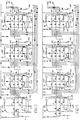
- Fig. 2 shows a washing phase in counter-current of columns 14, 16 and 18, with feed at 14B, 16B and 18B of water from pipe 3 and with outlet from column top 14A, 16A, 18A towards discharges 14C, 16C and 18C; washing is obtained in parallel for the various columns, thus separately for each of them.
- FIG. 3 shows a phase of passage of regenerants, which consist of a mixture of hot water from pipe 3, HC1 from pipe 5, and NaC1 from pipe 9, the mixture being fed in parallel for the individual columns, 14, 16 and 18 at the top 14A, 16A, 18A, with outlet from the bottom 14B, 16B and 18B to discharges 14C, 16C and 18C; the diluted NaC1 solution is acidified with HC1 and is active in equicurrent.
- This phase is rendered novel and characteristic by use of the acid in combination with sodium chloride.
- the acid that is present acts in particular on the upper zone of the resins in columns 14, 16 and 18 and causes detachment of the particles.
- An air bubbling phase follows (see Fig. 4), the air being fed by 14H, 16H and 18H, in order to ensure detachment of the particles; the air enters at 14B, 16B and 18B, and simultaneously in counter-current, that is while rising, treats the various columns separately and thus in parallel, and comes out from outlet 14A, 16A and 18A and discharge 14C, 16C and 18C.
- the acid that is present detaches the particles from the resin beds.
- a washing phase in counter-current follows with water entering from pipe 3, in an arrangement corresponding to that in Fig. 2; this is followed by a phase of interval or stasis similar to that envisaged after the phase illustrated in Fig. 2.
- a further phase, illustrated in Fig. 5, is a phase of counter-current passage of regenerants consisting of a solution of water entering by pipe 3 and a NaC1 solution entering by pipe 9, which are mixed and fed to the bottom inlets 14B, 16B and 18B of columns 14, 16 and 18, leaving by connectors 14A, 16A and 18A to the discharges 14C, 16C and 18C.
- This passage of regenerants takes place in counter-current and in parallel for the said resin columns and is a characteristic phase of the invention.
- phase illustrated in the diagram in Fig. 6 and consisting of passage of the NaC1 solution from pipe 9 and alkalised with NaOH from pipe 7, which solution is diluted with the hot water from pipe 3.
- This phase takes place in counter-current in the individual columns 14, 16 and 18 and in series in the various columns with inlet from the bottom at 18B of column 18 and removal by discharge 14E of column 14, while from each column the treatment mixture is removed through discharges 18F, 16F and 14F respectively; in order to ensure this removal a contrasting water feed is provided by pipe 3 through the top connectors 14A, 16A and 18A, thus facilitating elimination by the said intermediate discharges 18F, 16F and 14F.
- This phase is again particularly characteristic of the invention.
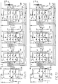
- Fig. 7 shows a subsequent regenerating phase involving passage of an NaC1 solution entering by pipe 9 and which, in dilute mixture with water entering by pipe 3, is fed to column 18 in counter-current and thus with feed by bottom connector 18B for discharge in conditions similar to those of the phase in Fig. 6 by outlet 18F to feed the bottom connector 16B of column 16 and to be discharged through the outlet connector 16F to discharge 16E; a limited hot water current is fed in the two columns 18 and 16 by the top connectors 18A and 16A in order to facilitate discharges from 18F and 16F.
- FIG. 8 shows a treatment of NaC1 solution in series and in counter-current starting from column 18 and then, still in counter-current, in column 16 and column 14, with the discharge from the various columns taking place through the intermediate discharges 18F, 16F and 14F with final discharge from 14E and with a water feed to column 18 for mixing the NaC1 solution, and with limited contrasting water feed from the top 18A, 16A and 14A of the three columns.
- This phase is again characteristic of the invention.
- a further phase, illustrated in Fig. 9, is a slow washing phase with shift into counter-current with ciculation in series from column 18 to column 16 and then column 14, the water being fed by 3 at the bottom into connector 18B of column 18, discharged by connector 18F, fed to bottom connector 16B of column 16, discharged by intermediate connector 16F, fed to bottom connector 14B of column 14 and expelled by connector 14F to discharge 14E; a limited contrasting water feed is provided at top connectors 14A, 16A and 18A of the three columns. In this way slow elimination of the regenerant is obtained.
- Fig. 11 again illustrates a subsequent rapid washing phase, which involves columns 14 and 16 in series and in equicurrent, with feed from pipe 3 and top connector 14A, and outlet from bottom connector 14B to feed top connector 16A, and outlet by bottom connector 16B for discharge by 16C. Washing of the two columns 14 and 16 is thus obtained with a particularly restricted water consumption, which is important in many cases.
- a phase illustrated in Fig. 12, of washing before the new operating phase, and consisting in a washing in series and in equicurrent of the three columns 14, 16 and 18, with water feed by pipe 3 to top connector 14A, outlet from bottom connector 14B for top connector 16A with outlet from bottom connector 16B to feed top connector 18A and outlet by bottom connector 18B to discharge 18C.
- This phase allows the end and completion of washing of columns 14 and 16, and a sufficient washing of the end column 18.
- a characteristic of the invention is the treatment of waste waters containing surface-active agents and dyes, especially for refluxes from dye-works and similar, and reliable absorption of dyes and ionic surface-active agents and also at least a good proportion of non-ionic surface-active agents is obtained, it being possible for the residues to be reused by recycling the waters coming from the treatment in the system in question.
- the method and system according to the invention may also be used for other treatments equivalent to that of dye-works' refluxes and similar, avoiding marked presence of greases.
Landscapes
- Chemical & Material Sciences (AREA)
- Organic Chemistry (AREA)
- Chemical Kinetics & Catalysis (AREA)
- Water Treatment By Sorption (AREA)
- Treatment Of Water By Ion Exchange (AREA)
- Paints Or Removers (AREA)
- Separation Using Semi-Permeable Membranes (AREA)
Claims (6)
- Procédé pour la régénération de résines échangeuses d'anions dans des systèmes de traitement d'eau à reflux comprenant au moins une colonne de traitement où les résines à régénérer sont traitées avec une solution de NaCl alcalinisée, caractérisé par les étapes de:a) un premier traitement avec une solution de NaCl acidifiée;b) un barbotage subséquent avec de l'air;c) un autre traitement avec une solution de NaCl;d) un traitement subséquent avec une solution de NaCl alcalinisée avec NaOH.
- Procédé selon la revendication 1, caractérisé en ce que ladite étape de traitement (a) avec la solution de NaCl acidifiée est réalisé en équi-courant et lesdites étapes de traitement subséquentes (c) avec la solution de NaCl et (d) avec la solution de NaCl alcalinisée sont réalisées à contre-courant, la direction de l'écoulement se rapportant à la direction usuelle d'écoulement pendant le mode de traitement d'eau du système.
- Procédé selon la revendication 1 ou 2, dans un système à plusieurs colonnes, caractérisé en ce que ladite étape de traitement (c) avec la solution de NaCl est mise en oeuvre à contre-courant en parallèle et ladite étape de traitement (d) avec la solution de NaCl alcalinisée est mise en oeuvre en séries de la dernière colonne à la première colonne.
- Procédé selon la revendication 3, caractérisé en ce qu'il comprend une autre étape (e) dans laquelle la première colonne (14), par rapport à la direction usuelle de l'écoulement pendant le traitement de l'eau est traitée à contre-courant avec la solution de NaCl alcalinisée avec NaOH tandis que la colonne ou les colonnes subséquentes (16, 18) sont traitées avec la solution de NaCl avec une décharge à un niveau inférieur plutôt qu'au-dessus de la masse de résine.
- Procédé selon la revendication 4, pour des systèmes à trois colonnes, caractérisé en ce que pendant ladite autre étape (e), les deux dernières colonnes (16, 18) sont traitées en séries et selon un démarrage à contre-courant à partir de la dernière colonne (18).
- Procédé selon l'une ou plusieurs des revendications 1 à 5 dans un système à plusieurs colonnes, caractérisé en ce qu'il comprend également les étapes de traitement suivantes de:f) un autre traitement avec une solution de NaCl à contre-courant et en séries à partir de la dernière colonne (18) à la première colonne (14),g) un lavage subséquent lent à contre-courant avec de l'eau en séries à partir de la dernière colonne à la première colonne, eth) un lavage subséquent rapide équi-courant avec de l'eau en séries de la première colonne à la dernière colonne si bien que les colonnes sont mises sous courant subséquemment.
Applications Claiming Priority (2)
| Application Number | Priority Date | Filing Date | Title |
|---|---|---|---|
| IT930990 | 1990-01-24 | ||
| IT9309A IT1239015B (it) | 1990-01-24 | 1990-01-24 | Metodo per la utilizzazione e la rigenerazione di resine anioniche in impianti di acque reflue di tintoria e simili. |
Publications (2)
| Publication Number | Publication Date |
|---|---|
| EP0442849A1 EP0442849A1 (fr) | 1991-08-21 |
| EP0442849B1 true EP0442849B1 (fr) | 1996-04-03 |
Family
ID=11128225
Family Applications (1)
| Application Number | Title | Priority Date | Filing Date |
|---|---|---|---|
| EP91830005A Expired - Lifetime EP0442849B1 (fr) | 1990-01-24 | 1991-01-15 | Méthode d'utilisation et régénération de résines anioniques dans des systèmes d'eau à contre-courant de solutions tinctoriales et analogues |
Country Status (4)
| Country | Link |
|---|---|
| EP (1) | EP0442849B1 (fr) |
| AT (1) | ATE136231T1 (fr) |
| DE (1) | DE69118426D1 (fr) |
| IT (1) | IT1239015B (fr) |
Cited By (1)
| Publication number | Priority date | Publication date | Assignee | Title |
|---|---|---|---|---|
| WO2005105677A1 (fr) * | 2004-04-30 | 2005-11-10 | Orica Australia Pty Ltd | Procede de regeneration |
Families Citing this family (2)
| Publication number | Priority date | Publication date | Assignee | Title |
|---|---|---|---|---|
| IN181196B (fr) * | 1993-01-20 | 1998-04-25 | Raju Manjarabad Venkataramanas | |
| AU2005266851B2 (en) * | 2004-07-28 | 2011-06-02 | Ixom Operations Pty Ltd | Plug-flow regeneration process |
Family Cites Families (5)
| Publication number | Priority date | Publication date | Assignee | Title |
|---|---|---|---|---|
| FR1279356A (fr) * | 1960-11-07 | 1961-12-22 | Minoc | Procédé pour la récupération de l'acide pyrrolidone carboxylique à partir de jusde betterave |
| CH643754A5 (en) * | 1980-03-28 | 1984-06-29 | Roshard Hans Rudolf | Process for converting a strongly basic ion exchanger resin into the bicarbonate form, and use of the ion exchanger resin regenerated according to this process |
| BE896812A (fr) * | 1983-05-24 | 1983-11-24 | Melyepitesi Tervezo | Procede de regeneration de resines echangeuses d'anions epuisees par le passage d'eau contenant des anions |
| FR2588486B1 (fr) * | 1985-10-15 | 1991-05-17 | Omnium Traitement Valorisa | Perfectionnement a la regeneration d'un lit de resine echangeuse d'ions pour l'elimination des nitrates de l'eau |
| GB8817083D0 (en) * | 1988-07-18 | 1988-08-24 | Solt G S | Improved method of ion exchange & apparatus for carrying out said method |
-
1990
- 1990-01-24 IT IT9309A patent/IT1239015B/it active IP Right Grant
-
1991
- 1991-01-15 AT AT91830005T patent/ATE136231T1/de not_active IP Right Cessation
- 1991-01-15 DE DE69118426T patent/DE69118426D1/de not_active Expired - Lifetime
- 1991-01-15 EP EP91830005A patent/EP0442849B1/fr not_active Expired - Lifetime
Cited By (1)
| Publication number | Priority date | Publication date | Assignee | Title |
|---|---|---|---|---|
| WO2005105677A1 (fr) * | 2004-04-30 | 2005-11-10 | Orica Australia Pty Ltd | Procede de regeneration |
Also Published As
| Publication number | Publication date |
|---|---|
| ATE136231T1 (de) | 1996-04-15 |
| IT9009309A1 (it) | 1991-07-24 |
| IT9009309A0 (it) | 1990-01-24 |
| DE69118426D1 (de) | 1996-05-09 |
| EP0442849A1 (fr) | 1991-08-21 |
| IT1239015B (it) | 1993-09-20 |
Similar Documents
| Publication | Publication Date | Title |
|---|---|---|
| JPS61209087A (ja) | 貫流型の水脱塩方式及び方法 | |
| JP6873972B2 (ja) | 混合床樹脂の再生 | |
| KR100463268B1 (ko) | 혼상식(混床式) 당액 정제장치 및 그의 재생법 | |
| EP0442849B1 (fr) | Méthode d'utilisation et régénération de résines anioniques dans des systèmes d'eau à contre-courant de solutions tinctoriales et analogues | |
| US3074820A (en) | Liquid-solid ion exchange process | |
| JPS6231613B2 (fr) | ||
| AU640472B2 (en) | Ion exchange apparatus | |
| US4523998A (en) | Continuous ion exchange process using thermally regenerable liquid ion exchangers | |
| US3537989A (en) | Demineralization system | |
| US3975267A (en) | Liquid treating system | |
| JP3765653B2 (ja) | 混床式イオン交換樹脂塔の混合樹脂の分離方法および混床式ショ糖精製装置の再生方法 | |
| US3642616A (en) | Continuous method for treating liquids | |
| JPH10180252A (ja) | 純水製造方法及びイオン交換塔 | |
| JP2891820B2 (ja) | イオン交換樹脂の再生法 | |
| KR0161346B1 (ko) | 탑외 재생형 혼상식 복수 탈염설비의 이온교환수지 이송분리 재생방법 및 장치 | |
| JP4245745B2 (ja) | 混床式糖液精製装置 | |
| JP2654053B2 (ja) | 復水脱塩装置 | |
| US3692670A (en) | Treatment of cation and anion exchange resins with sodium sulfite | |
| JP2896418B2 (ja) | 調水装置 | |
| JP2576155B2 (ja) | 複層式イオン交換装置 | |
| JP2597552Y2 (ja) | 純水製造設備 | |
| JP2001079424A (ja) | イオン交換樹脂の再生設備と再生方法 | |
| SU1627245A1 (ru) | Способ регенерации катионитовых и анионитовых фильтров в установке дл обессоливани и ум гчени воды | |
| JPS6259630B2 (fr) | ||
| JPS6133623B2 (fr) |
Legal Events
| Date | Code | Title | Description |
|---|---|---|---|
| PUAI | Public reference made under article 153(3) epc to a published international application that has entered the european phase |
Free format text: ORIGINAL CODE: 0009012 |
|
| AK | Designated contracting states |
Kind code of ref document: A1 Designated state(s): AT BE CH DE DK ES FR GB GR IT LI LU NL SE |
|
| 17P | Request for examination filed |
Effective date: 19911025 |
|
| 17Q | First examination report despatched |
Effective date: 19921104 |
|
| GRAA | (expected) grant |
Free format text: ORIGINAL CODE: 0009210 |
|
| AK | Designated contracting states |
Kind code of ref document: B1 Designated state(s): AT BE CH DE DK ES FR GB GR IT LI LU NL SE |
|
| PG25 | Lapsed in a contracting state [announced via postgrant information from national office to epo] |
Ref country code: DK Effective date: 19960403 Ref country code: ES Free format text: THE PATENT HAS BEEN ANNULLED BY A DECISION OF A NATIONAL AUTHORITY Effective date: 19960403 Ref country code: LI Effective date: 19960403 Ref country code: GR Free format text: LAPSE BECAUSE OF FAILURE TO SUBMIT A TRANSLATION OF THE DESCRIPTION OR TO PAY THE FEE WITHIN THE PRESCRIBED TIME-LIMIT Effective date: 19960403 Ref country code: AT Effective date: 19960403 Ref country code: CH Effective date: 19960403 Ref country code: BE Effective date: 19960403 Ref country code: NL Free format text: LAPSE BECAUSE OF FAILURE TO SUBMIT A TRANSLATION OF THE DESCRIPTION OR TO PAY THE FEE WITHIN THE PRESCRIBED TIME-LIMIT Effective date: 19960403 |
|
| REF | Corresponds to: |
Ref document number: 136231 Country of ref document: AT Date of ref document: 19960415 Kind code of ref document: T |
|
| REF | Corresponds to: |
Ref document number: 69118426 Country of ref document: DE Date of ref document: 19960509 |
|
| ITF | It: translation for a ep patent filed | ||
| PG25 | Lapsed in a contracting state [announced via postgrant information from national office to epo] |
Ref country code: SE Effective date: 19960703 |
|
| PG25 | Lapsed in a contracting state [announced via postgrant information from national office to epo] |
Ref country code: DE Effective date: 19960704 |
|
| ET | Fr: translation filed | ||
| NLV1 | Nl: lapsed or annulled due to failure to fulfill the requirements of art. 29p and 29m of the patents act | ||
| REG | Reference to a national code |
Ref country code: CH Ref legal event code: PL |
|
| PGFP | Annual fee paid to national office [announced via postgrant information from national office to epo] |
Ref country code: FR Payment date: 19970114 Year of fee payment: 7 |
|
| PG25 | Lapsed in a contracting state [announced via postgrant information from national office to epo] |
Ref country code: GB Effective date: 19970115 |
|
| PG25 | Lapsed in a contracting state [announced via postgrant information from national office to epo] |
Ref country code: LU Free format text: LAPSE BECAUSE OF NON-PAYMENT OF DUE FEES Effective date: 19970131 |
|
| PLBE | No opposition filed within time limit |
Free format text: ORIGINAL CODE: 0009261 |
|
| STAA | Information on the status of an ep patent application or granted ep patent |
Free format text: STATUS: NO OPPOSITION FILED WITHIN TIME LIMIT |
|
| 26N | No opposition filed | ||
| GBPC | Gb: european patent ceased through non-payment of renewal fee |
Effective date: 19970115 |
|
| PG25 | Lapsed in a contracting state [announced via postgrant information from national office to epo] |
Ref country code: FR Free format text: THE PATENT HAS BEEN ANNULLED BY A DECISION OF A NATIONAL AUTHORITY Effective date: 19980131 |
|
| REG | Reference to a national code |
Ref country code: FR Ref legal event code: ST |
|
| PGFP | Annual fee paid to national office [announced via postgrant information from national office to epo] |
Ref country code: IT Payment date: 20080130 Year of fee payment: 18 |
|
| PG25 | Lapsed in a contracting state [announced via postgrant information from national office to epo] |
Ref country code: IT Free format text: LAPSE BECAUSE OF NON-PAYMENT OF DUE FEES Effective date: 20090115 |