EP0442899B1 - Flügel schubdüse - Google Patents
Flügel schubdüse Download PDFInfo
- Publication number
- EP0442899B1 EP0442899B1 EP89911315A EP89911315A EP0442899B1 EP 0442899 B1 EP0442899 B1 EP 0442899B1 EP 89911315 A EP89911315 A EP 89911315A EP 89911315 A EP89911315 A EP 89911315A EP 0442899 B1 EP0442899 B1 EP 0442899B1
- Authority
- EP
- European Patent Office
- Prior art keywords
- vane member
- section
- passageway
- throat section
- wall portion
- Prior art date
- Legal status (The legal status is an assumption and is not a legal conclusion. Google has not performed a legal analysis and makes no representation as to the accuracy of the status listed.)
- Expired - Lifetime
Links
- 238000000034 method Methods 0.000 claims abstract description 7
- 239000012530 fluid Substances 0.000 claims description 9
- 238000004140 cleaning Methods 0.000 description 3
- 230000007704 transition Effects 0.000 description 3
- OKTJSMMVPCPJKN-UHFFFAOYSA-N Carbon Chemical compound [C] OKTJSMMVPCPJKN-UHFFFAOYSA-N 0.000 description 2
- 229910052799 carbon Inorganic materials 0.000 description 2
- 239000000356 contaminant Substances 0.000 description 2
- 238000012986 modification Methods 0.000 description 2
- 230000004048 modification Effects 0.000 description 2
- 239000003380 propellant Substances 0.000 description 2
- 238000007789 sealing Methods 0.000 description 2
- 238000011144 upstream manufacturing Methods 0.000 description 2
- XAGFODPZIPBFFR-UHFFFAOYSA-N aluminium Chemical compound [Al] XAGFODPZIPBFFR-UHFFFAOYSA-N 0.000 description 1
- 229910052782 aluminium Inorganic materials 0.000 description 1
- 239000004411 aluminium Substances 0.000 description 1
- 238000010276 construction Methods 0.000 description 1
- 230000000694 effects Effects 0.000 description 1
- 239000000446 fuel Substances 0.000 description 1
- 239000000463 material Substances 0.000 description 1
Images


Classifications
-
- F—MECHANICAL ENGINEERING; LIGHTING; HEATING; WEAPONS; BLASTING
- F02—COMBUSTION ENGINES; HOT-GAS OR COMBUSTION-PRODUCT ENGINE PLANTS
- F02K—JET-PROPULSION PLANTS
- F02K9/00—Rocket-engine plants, i.e. plants carrying both fuel and oxidant therefor; Control thereof
- F02K9/80—Rocket-engine plants, i.e. plants carrying both fuel and oxidant therefor; Control thereof characterised by thrust or thrust vector control
-
- B—PERFORMING OPERATIONS; TRANSPORTING
- B64—AIRCRAFT; AVIATION; COSMONAUTICS
- B64C—AEROPLANES; HELICOPTERS
- B64C15/00—Attitude, flight direction, or altitude control by jet reaction
- B64C15/02—Attitude, flight direction, or altitude control by jet reaction the jets being propulsion jets
-
- F—MECHANICAL ENGINEERING; LIGHTING; HEATING; WEAPONS; BLASTING
- F02—COMBUSTION ENGINES; HOT-GAS OR COMBUSTION-PRODUCT ENGINE PLANTS
- F02K—JET-PROPULSION PLANTS
- F02K1/00—Plants characterised by the form or arrangement of the jet pipe or nozzle; Jet pipes or nozzles peculiar thereto
- F02K1/002—Plants characterised by the form or arrangement of the jet pipe or nozzle; Jet pipes or nozzles peculiar thereto with means to modify the direction of thrust vector
- F02K1/006—Plants characterised by the form or arrangement of the jet pipe or nozzle; Jet pipes or nozzles peculiar thereto with means to modify the direction of thrust vector within one plane only
-
- F—MECHANICAL ENGINEERING; LIGHTING; HEATING; WEAPONS; BLASTING
- F42—AMMUNITION; BLASTING
- F42B—EXPLOSIVE CHARGES, e.g. FOR BLASTING, FIREWORKS, AMMUNITION
- F42B10/00—Means for influencing, e.g. improving, the aerodynamic properties of projectiles or missiles; Arrangements on projectiles or missiles for stabilising, steering, range-reducing, range-increasing or fall-retarding
- F42B10/60—Steering arrangements
- F42B10/66—Steering by varying intensity or direction of thrust
- F42B10/665—Steering by varying intensity or direction of thrust characterised by using a nozzle provided with at least a deflector mounted within the nozzle
Definitions
- This invention relates generally to the field of nozzles through which a fluid jet is discharged, and, more particularly, to various forms of improved vane-type nozzles for selectively controlling the magnitude and direction of the thrust vector of hot gas discharged therethrough, and to improved methods of controlling the operation of such nozzles.
- Converging-diverging nozzles are commonly used to discharge a fluid, typically a gas, to produce a fluid jet which, in turn, creates thrust.
- a fluid jet may be used to control the attitude of an airborne vehicle.
- Such nozzles typically have a converging entrance section, a narrowed throat section, and a diverging exit section. Each of these sections is typically of fixed dimension and proportion, and the flow of fluid is controlled by an upstream valve having relatively-slidable parts or small-area orifices. In some applications, contaminants in the hot gas, possibly molten aluminium, may foul these sliding parts and/or orifices.
- an improved thruster nozzle which is relatively insensitive to contaminants in the discharged fluid, which avoids relatively-sliding parts and small orifices, which is generally self-cleaning, and which affords the capability of selectively varying the flow therethrough at the throat.
- An example of such a nozzle is disclosed in US-A-2799989 in which the throat section is defined by the facing surfaces of a pair of pivoted vane members which are selectively rocked by actuators to vary the angular positions of the vane members and thereby control the area of the throat section.
- the present invention broadly provides various forms of improved vane-type nozzles, and various accompanying forms of operating such nozzles.
- the invention provides an adjustable nozzle comprising a body having a flow passageway therethrough, said passageway being configured to define a converging entrance section, a narrowed throat section and a diverging exit section, characterized in that: said body has a surface forming a stationary wall portion of said throat section; a single vane member is pivotally mounted on said body, said vane member having a first surface facing into said passageway to form a movable wall portion of said throat section, said first surface being eccentric to the pivotal axis of the vane member, and said vane member being rotatable about its pivotal axis to an angular position at which said first surface engages said stationary wall portion of said throat section to close said passageway; and an actuator mounted on said body and operable to selectively vary the angular position of said vane member relative to said body; whereby said actuator may be selectively operated to controllably vary the orifice area of said throat section.
- the invention provides an improved method of varying the orifice area of a nozzle having a body with a flow passageway there-through, said passageway having a converging entrance section, a narrowed throat section, and a diverging exit section, characterized by the steps of: providing said body with a surface forming a stationary wall portion of said throat section; providing a single vane member having a first surface positioned eccentrically to a pivotal axis; mounting said vane member on said body for pivotal movement about said axis such that said first surface forms a movable wall portion of said throat section and such that said vane member is selectively rotatable about its pivotal axis to an angular position at which said first surface engages said stationary wall portion of said throat section to close said passageway; and controllably varying the angular position of said vane member relative to said body, thereby to selectively vary the orifice area of said throat section.
- the invention thus provides an improved vane-type nozzle having a selectively-variable orifice area, which is self-cleaning and therefore tolerant of metal-contaminated propellants, and which can be operated to selectively vary the magnitude and/or direction of the thrust vector of gas discharged therethrough.
- the terms “horizontal”, “vertical”, “left”, “right”, “up” and “down”, as well as adjectival and adverbial derivatives thereof simply refer to the orientation of the illustrated structure as the particular drawing figure faces the reader.
- the terms “inwardly” and “outwardly” refer to the orientation of a surface relative to its axis of elongation, or axis of rotation, as appropriate.
- this invention provides various forms of improved vane-type converging-diverging jet nozzles, and methods of operating same.
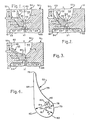
- the thrust vector of gas discharged through the improved nozzle is along axis y-y.
- a first preferred form of the improved nozzle is shown in Figures 1 to 4 and a second in Figures 5 to 8. While both of these embodiments may have certain element(s) in common, each is specifically different. Hence, the two embodiments will be described seriatim herebelow.
- the improved converging-diverging nozzle is shown as including a body 51, and a single vane member 52.
- Body 51 is shown as being provided with a vertical through-passageway 53 extending between its lower or inner side 54, and its upper or outer side 55.
- the passageway is configured as a converging-diverging nozzle, and includes a lower entrance section 56, an intermediate narrowed throat section 58, and an upper exit section 59.
- the passageway is elongated along a vertical plane perpendicular to the plane of the paper, and extends between a pair of longitudinally-spaced end walls, one of which is indicated at 60.
- the single vane member 52 is mounted in the passageway 53, and to accommodate this, the facing side surfaces of the passageway are configured differently.
- the left wall, adjacent which the vane member is mounted, is shown in transverse cross-section as sequentially including: a rightwardly-facing planar vertical surface 61, a downwardly-facing planar horizontal surface 62, a rightwardly-and downwardly-facing inclined planar surface 63 forming a portion of the entrance section 56, a rightwardly- and upwardly-facing circularly-segmented concave surface 64, an upwardly- and rightwardly-facing planar inclined surface 65 tangentially joining the left margin of surface 64, and a rightwardly-facing planar vertical surface 66 continuing upwardly therefrom to join outer surface 55.
- the passageway right wall differs from this and specifically includes: a leftwardly-facing planar vertical surface 68, a downwardly-facing planar horizontal surface 69, a downwardly- and leftwardly-facing inclined planar surface 70 forming with left wall surface 63 the entrance section therebetween, a leftwardly-facing convex arcuate surface 71 tangentially joining surface 70 and forming the right wall of the throat section, and an upwardly- and leftwardly-facing parabolically-segmented concave surface 72 tangentially joining surface 71 and continuing upwardly therefrom to join upper surface 55.
- a longitudinally-extending U-shaped recess extends normally into surface 64 to receive and accommodate a carbon seal strip 73 which sealingly and wipingly engages the facing surface of vane member 52.
- the vane member 52 is specially-configured and horizontally-elongated When seen in transverse cross-section ( Figure 4), this vane member is sequentially bounded by: an uppermost semi-circular convex tip surface 74, a parabolically-segmented concave surface 75 extending downwardly and rightwardly from the right margin of surface 74, a circularly-segmented first surface 76 of radius R1 generated about point 78 and occupying an arc distance of about 60°, a rightwardly-facing vertical surface 79, a second circularly-segmented surface 80 of radius R2 generated about point 81 and occupying an arc distance of about 80°, a third circularly-segmented convex surface 82 of radius R3 generated about point 83 and occupying an arc distance of about 80°, and a leftwardly-facing planar vertical surface 84 continuing upwardly therefrom to join the left margin of convex tip surface 74.
- a Bourdon cable actuator 88 is shown as being operatively arranged to selectively move the vane member to the desired angular position relative to the body.
- the right wall of the passageway is complementarily configured to generally simulate the shape of the facing surfaces of the vane member and the left wall, when surface 84 of the vane member is vertical.
- the vane member 52 is shown as being in an angular position at which vane member surface 84 is vertical, as also shown in Figure 4. In this position, hot gas may be discharged vertically upwardly through the passageway, as represented by thrust vector T.
- the vane member is moved from the position shown in Figure 1 in a counterclockwise direction to the intermediate position shown in Figure 2, the magnitude and direction of thrust vector T will change.
- Figure 2 the magnitude of the thrust vector is shown as being reduced from that shown in Figure 1, owing to the fact that vane member surfaces 76, 79 have moved closer to the opposing stationary surfaces of the passageway right wall.
- the thrust vector now of reduced magnitude, is shown as being directed upwardly and leftwardly.
- Figure 3 depicts the vane member as having been rotated further in a counterclockwise direction from the position shown in Figure 2, such that a proximate portion of the vane member, this portion being generally arranged between surfaces 79, 80, engages the transversely-opposite right wall of the passageway substantially in line contact to close the throat section. This represents a closed condition of the nozzle.
- this embodiment may be operated to selectively vary the magnitude and/or direction of the thrust vector discharged through the passageway.
- a second embodiment of the improved nozzle arrangement, generally indicated at 120, is shown in Figures 5-7 as including a body 121 and a single vane member 122.
- Body 121 is again shown as being provided with a vertical through-passageway 123 extending between a lower or inner side 124 and an upper or outer side 125.
- the passageway is elongated along a vertical plane extending out of the paper, and is bounded by longitudinally-spaced transverse end walls, one of which is indicated as 126. The other end wall does not appear in Figures 5-7 simply because these views are taken through an intermediate portion of the structure.
- the passageway is again configured as an elongated converging-diverging nozzle, and includes a lower entrance section 128, and intermediate narrowed throat section 129, and an upper exit section 130.
- the left and right side walls of the body passageway are asymmetrical.
- the left wall is shown as including: a rightwardly-facing vertical surface 131, a downwardly-facing horizontal surface 132, a downwardly- and rightwardly-facing inclined planar surface 133, an upwardly-facing horizontal surface 134, and arcuate quarter-round concave surface 135 tangentially joining surface 134, and a rightwardly-facing vertical surface 136 tangentially joining surface 135 and extending upwardly therefrom to join upper surface 125.
- Vane member 122 is operatively mounted within the L-shaped recess defined in the left wall by surfaces 134, 135 and 136. This vane member 122 is specially-configured and horizontally-elongated along an axis extending out of the paper.
- the vane member When seen in transverse cross-section ( Figure 8), the vane member is sequentially bounded by: an uppermost semi-circular convex tip surface 106, an upwardly- and rightwardly-facing concave parabolically-segmented surface 108 extending downwardly from the right margin of tip surface 106, a first convex circularly-segmented surface 109 of radius R1 about point 110, a second convex circularly-segmented surface 111 of radius R2 generated about point 112, and a leftwardly- facing planar vertical surface 113 extending upwardly therefrom to join the left margin of tip surface 106.
- the various adjacent surfaces of the vane member are shown as being in generally-smooth continuous transition.
- the vane member is further shown as being provided with a longitudinally-extending horizontal through-hole 114, concentric with point 112, to receive and accommodate a pivot pin by which the vane member is rotatably mounted on the body.
- radius R1 is 0.488 inches [12.40 mm] and occupies an arc distance of 107°17', while radius R2 is 0.250 inches [6.35 mm] and occupies an arc distance of 120°0'.
- Points 110,112 are separated by a horizontal distance (i.e., dimension A in Figure 8) of 0.119 inches [3.02 mm], and by a vertical distance (i.e., dimension B) of 0.206 inches [5.23 mm].
- An elongated recess having a U-shaped transverse cross-section, is shown as extending normally into the body from arcuate surface 135 to receive and accommodate an elongated carbon sealing strip 138, or equivalent, which sealingly and wipingly engages the outer surface of the vane member.
- the right wall of the passageway is shown as being sequentially bounded by: a leftwardly-facing vertical surface 139, a downwardly-facing horizontal surface 140, a downwardly- and leftwardly-facing inclined planar surface 141 arranged to face left wall surface 133, and arcuate nose surface 142 proximate the throat section, and an upwardly- and leftwardly-facing parabolically-segmented surface 143 continuing upwardly and rightwardly therefrom to join upper surface 125.
- Surfaces 141-143 are in generally-smooth continuous transition, one to another.
- the right wall is configured to generally simulate the facing surface of the left wall and the vane member, when the vane member is in its vertical position as shown in Figure 5.
- the lower portion of surface 141 is generally symmetrical with left wall surface 133
- rounded nose 142 is generally symmetrical with the facing surface of the vane member
- surface 143 is generally symmetrical with vane surface 108.
- a Bourdon cable-type actuator 144 penetrates the body and engages the vane member, and may be selectively operated to controllably vary the angular position of the vane member, as previously described.
- the vane member When the vane member is vertical, as shown in Figure 5, the orifice area of the throat section will be at its maximum, and, because of the substantially-symmetrical shape of the facing surfaces forming the passageway, the thrust vector T will be substantially vertical.
- Figure 6 shows the vane member as having been rotated from the position shown in Figure 5 in a clockwise direction through an arc distance of about 18°. The effect of this is to move vane member surface 109 toward right rounded surface 142, thereby reducing the orifice area of the throat section.
- the facing surfaces will be generally symmetrical about an axis y-y extending upwardly and rightwardly.
- the thrust vector will be directed upwardly and rightwardly, but will be of reduced magnitude as compared with that shown in Figure 5.
- Figure 7 shows the vane member as having been rotated still further in clockwise direction until vane member surface 109 impinges upon rightward surface 142 substantially in line contact to close the throat section and reduce the magnitude of the thrust vector to zero.
- the improved vane member may be operated to vary the direction and magnitude of the thrust vector.
- the materials of construction are not deemed critical, and may be selected from any number suitable for the intended purpose.
- the end walls need not necessarily be vertical, and may be inclined or arcuate, as desired.
- the vane member may be moved to various positions to vary the magnitude and direction of the thrust vector discharged through the passageway.
- the size, shape and configuration of the vane member may also be changed and modified, either conjunctively or independently of the shape of the opposing wall of the passageway, as appropriate and as desired.
- the vane member surface forming the exit section need not necessarily be a parabolic segment. In some cases, this surface may be planar or have some other shape or configuration. It is presently preferred that the two facing surfaces of the throat section selectively engage one another in line contact, although this is not invariable.
- the vane member may be operated to vary the cross-sectional area of the throat section, without altering the shape and configuration of the exit section. In other cases, the vane member may be joined to the body by means of a web section and flexes to permit the desired angular movement of the associated vane member.
- the nature and type of the sealing strip or member may be changed or varied, as desired.
- the invention provides various forms of an improved vane type nozzle, which is particularly suited to vary the thrust vector of gas discharged therethrough, which has no relatively sliding surfaces directly exposed to the discharged gas, which is self-cleaning, and which is tolerant of contaminant-laden fuels and propellants.
- the invention provides an improved converging-diverging nozzle in which a single vane member is operatively mounted on a body in a flow passageway therethrough, which vane member may be selectively moved relative to the body to vary the direction and magnitude of the thrust vector of fluid discharged therethrough.
- the improved nozzle obviates the need for an upstream valve to control the flow of gas to the nozzle. Rather, the appropriate flow-regulating action is provided directly in the throat section.
Landscapes
- Engineering & Computer Science (AREA)
- Chemical & Material Sciences (AREA)
- Combustion & Propulsion (AREA)
- General Engineering & Computer Science (AREA)
- Mechanical Engineering (AREA)
- Aviation & Aerospace Engineering (AREA)
- Physics & Mathematics (AREA)
- Fluid Mechanics (AREA)
- Nozzles (AREA)
Claims (12)
- Eine einstellbare Düse mit einem Körper (51; 121) mit Strömungsdurchtritt (53; 123), wobei der Durchtritt einen konvergierenden Eintrittsbereich (56; 128), einen verengten Durchlaßbereich (59; 129) und einen divergierenden Austrittsbereich (59; 130) bildet, dadurch gekennzeichnet, daß:
der Körper (51; 121) eine Fläche aufweist, die einen feststehenden Wandteil (71; 142) des Durchlaßbereichs bildet;
ein einzelner Flügel (52; 122) drehbar auf dem Körper angebracht ist wobei der Flügel eine erste Fläche (76, 79, 80; 109) hat, die in den Durchtritt (53; 123) weist, um so einen beweglichen Wandteil des Durchlaßbereichs zu bilden, die erste Fläche exzentrisch zur Drehachse (83; 112) des Flügels gelegen ist und der Flügel um seine Drehachse in eine Winkelposition gedreht werden kann, in der die erste Fläche (79, 80; 109) mit dem feststehenden Wandteil (71; 142) des Durchlaßbereichs in Eingriff kommt, um den Durchtritt zu verschließen; und
eine Betätigungseinrichtung (88; 144) auf dem Körper angebracht ist und zum wahlweisen Verändern der Winkelposition des Flügels (52; 122) zum Körper eingesetzt werden kann;
wodurch die Betätigungseinrichtung (88; 144) wahlweise zur steuernden Veränderung der Öffnungsgröße des Durchlaßbereichs (58; 129) zum Einsatz gebracht werden kann. - Einstellbare Düse nach Anspruch 1, wobei der Flügel (52; 122) eine zweite Fläche (75; 108) aufweist, die einen beweglichen Wandteil des Austrittsbereichs (59; 130) bildet.
- Einstellbare Düse nach Anspruch 2, wobei sich die zweite Fläche (75; 108) tangential an die erste Fläche (76, 79, 80; 109) des Flügels anfügt.
- Einstellbare Düse nach Anspruch 2, wobei die zweite Fläche (75; 108) im Querschnitt im wesentlichen parabelförmig ist.
- Einstellbare Düse nach Anspruch 1, wobei der Flügel (52; 122) teilweise gegenüber dem Druck eines Fluids im Eintrittsbereich (56; 128) ausgeglichen ist.
- Einstellbare Düse nach Anspruch 1, wobei der bewegliche Wandteil i (76, 79, 80; 109) wahlweise mit dem feststehenden Wandteil (71; 142) in linearem Kontakt ineinandergreift um den Durchlaßbereich (58; 129) zu verschließen.
- Einstellbare Düse nach Anspruch 1, wobei die erste Fläche (76, 79, 80; 109) im Querschnitt als kreisförmiges Segment ausgebildet ist.
- Einstellbare Düse nach Anspruch 7, wobei die erste Fläche einen Bogenabstand von etwa 180° einnimmt.
- Einstellbare Düse nach Anspruch 7, wobei die erste Fläche zylindrisch ist.
- Verfahren zur Veränderung der Öffnungsgröße einer Düse, die einen Körper (51; 121) mit Strömungsdurchtritt (53; 123) aufweist, wobei der Durchtritt einen konvergierenden Eintrittsbereich (56; 128), einen verengten Durchlaßbereich (58; 129) und einen divergierenden Austrittsbereich (59; 130) hat, gekennzeichnet durch die folgenden Schritte:
Schaffung des Körpers mit einer Fläche, die einen feststehenden Wandteil (71; 142) des Durchlaßbereichs (58; 129) bildet:
Schaffung eines einzelnen Flügels (51; 122) mit einer ersten Fläche (76, 79, 80; 109), die exzentrisch zu einer Drehachse (83; 112) gelegen ist:
Anbringung des Flügels auf dem Körper zur Drehbewegung um die Achse, so daß die erste Fläche (76, 79, 80; 109) einen beweglichen Wandteil des Durchlaßbereichs (58; 129) bildet und der Flügel wahlweise um seine Drehachse in eine Winkelposition gedreht werden kann, in der die erste Fläche mit dem feststehenden Wandteil (71; 142) des Durchlaßbereichs in Eingriff kommt um den Durchtritt (53; 123) zu verschließen; und
die steuerbare Veränderung der Winkelposition des Flügels (52; 122) zum Körper, wodurch die Öffnungsgröße des Durchlaßbereichs (58; 129) wahlweise verändert werden kann. - Verfahren nach Anspruch 10, das zusätzlich die steuerbare Veränderung des Schubvektors des durch den Durchtritt (53; 123) strömenden Fluids umfaßt.
- Verfahren nach Anspruch 10, das zusätzlich die wahlweise Veränderung der Mittellinie der Düse als Funktion der Winkelposition des Flügels (52; 122) umfaßt.
Applications Claiming Priority (1)
| Application Number | Priority Date | Filing Date | Title |
|---|---|---|---|
| PCT/US1989/003602 WO1989012741A1 (en) | 1989-08-21 | 1989-08-21 | Vane-type thrust vectoring nozzle |
Publications (3)
| Publication Number | Publication Date |
|---|---|
| EP0442899A1 EP0442899A1 (de) | 1991-08-28 |
| EP0442899A4 EP0442899A4 (en) | 1992-01-08 |
| EP0442899B1 true EP0442899B1 (de) | 1994-04-27 |
Family
ID=22215179
Family Applications (1)
| Application Number | Title | Priority Date | Filing Date |
|---|---|---|---|
| EP89911315A Expired - Lifetime EP0442899B1 (de) | 1989-08-21 | 1989-08-21 | Flügel schubdüse |
Country Status (4)
| Country | Link |
|---|---|
| US (1) | US5110047A (de) |
| EP (1) | EP0442899B1 (de) |
| DE (1) | DE68915000T2 (de) |
| WO (1) | WO1989012741A1 (de) |
Families Citing this family (13)
| Publication number | Priority date | Publication date | Assignee | Title |
|---|---|---|---|---|
| US5294055A (en) * | 1992-09-08 | 1994-03-15 | Mcdonnell Douglas Corporation | Rotatable arms for thrust vectoring and changing the area of a nozzle throat |
| GB2277559A (en) * | 1993-04-30 | 1994-11-02 | Marconi Gec Ltd | Variable area convergent-divergent nozzle. |
| DE4426195C2 (de) * | 1994-07-23 | 1998-02-05 | Daimler Benz Aerospace Ag | Schubdüse in Rechteckbauweise für Strahltriebwerke |
| US6681560B2 (en) | 2002-01-08 | 2004-01-27 | Atlantic Research Corporation | Nozzle throat area control apparatus and method |
| SE527787C2 (sv) * | 2004-11-05 | 2006-06-07 | Volvo Aero Corp | Utloppsanordning till en jetmotor och en jetmotor innefattande sådan utloppsanordning |
| US7493914B2 (en) * | 2005-07-20 | 2009-02-24 | Welker, Inc. | Newtonian thrust cowl array |
| US7842898B2 (en) * | 2007-10-19 | 2010-11-30 | Honeywell International Inc. | Variable orifice torch |
| FR2945316B1 (fr) * | 2009-01-27 | 2013-01-04 | Michel Aguilar | Reacteur, notamment reacteur pour aeronef |
| CN103303451B (zh) * | 2013-06-17 | 2015-09-23 | 北京理工大学 | 一种液压驱动的全矢量喷水推进器喷口 |
| CN107313875A (zh) * | 2017-06-16 | 2017-11-03 | 李新亚 | 潜水船装喷气发动机的矢量喷管 |
| US10144394B1 (en) * | 2017-11-08 | 2018-12-04 | Uber Technologies, Inc. | Nozzles and systems for cleaning vehicle sensors |
| CN110657043B (zh) * | 2019-09-09 | 2022-02-08 | 南京航空航天大学 | 一种机械扰动式喉道偏移式气动矢量喷管 |
| CN113685272B (zh) * | 2021-10-26 | 2021-12-24 | 中国航发四川燃气涡轮研究院 | 一种大尺寸薄壁非对称对开的圆转方机匣 |
Family Cites Families (10)
| Publication number | Priority date | Publication date | Assignee | Title |
|---|---|---|---|---|
| US2366264A (en) * | 1943-06-04 | 1945-01-02 | Mack Mfg Corp | Nozzle |
| US2799989A (en) * | 1954-09-24 | 1957-07-23 | Peter G Kappus | Variable area jet nozzle |
| GB874427A (en) * | 1958-06-03 | 1961-08-10 | Alec Tucker | New or improved speed and direction control means for water craft |
| US3302890A (en) * | 1964-07-10 | 1967-02-07 | Atlantic Res Corp | Rocket nozzle |
| US3304865A (en) * | 1965-04-21 | 1967-02-21 | Robert L Gungle | Self-sealing, unbonded, rocket motor nozzle closure |
| US3979067A (en) * | 1975-04-28 | 1976-09-07 | General Electric Company | Actuating means for a thrust vectoring gas turbine engine exhaust nozzle |
| GB2155552B (en) * | 1981-02-24 | 1986-02-26 | Rolls Royce | Adjustable jet propulsion nozzle |
| GB2194597B (en) * | 1986-08-29 | 1990-07-25 | Rolls Royce Plc | A variable area exhaust nozzle for a gas turbine engine |
| US4763840A (en) * | 1987-04-09 | 1988-08-16 | United Technologies Corporation | Thrust vectoring exhaust nozzle arrangement |
| US4798328A (en) * | 1987-05-22 | 1989-01-17 | United Technologies Corporation | Area controlled, thrust vectoring vane cascade with nutating control vane |
-
1989
- 1989-08-21 WO PCT/US1989/003602 patent/WO1989012741A1/en not_active Ceased
- 1989-08-21 DE DE68915000T patent/DE68915000T2/de not_active Expired - Fee Related
- 1989-08-21 EP EP89911315A patent/EP0442899B1/de not_active Expired - Lifetime
- 1989-08-21 US US07/474,744 patent/US5110047A/en not_active Expired - Fee Related
Also Published As
| Publication number | Publication date |
|---|---|
| WO1989012741A1 (en) | 1989-12-28 |
| EP0442899A1 (de) | 1991-08-28 |
| DE68915000T2 (de) | 1994-11-03 |
| EP0442899A4 (en) | 1992-01-08 |
| DE68915000D1 (de) | 1994-06-01 |
| US5110047A (en) | 1992-05-05 |
Similar Documents
| Publication | Publication Date | Title |
|---|---|---|
| EP0442899B1 (de) | Flügel schubdüse | |
| US4778109A (en) | Adjustable two dimensional nozzle for aircraft jet engines | |
| US4836451A (en) | Yaw and pitch convergent-divergent thrust vectoring nozzle | |
| US5285637A (en) | Seal centering and restraining device for an axisymmetric convergent/divergent nozzle | |
| US5039014A (en) | Axisymmetric vectoring exhaust nozzle seal | |
| RU2145390C1 (ru) | Устройство реверсирования тяги турбореактивного двигателя с поворотными створками, содержащее отклоняющие лопатки, связанные с неподвижной конструкцией | |
| US6079201A (en) | Self-closing pivoting door thrust reverser | |
| US5115979A (en) | Conforming plunger seal assembly | |
| US5915653A (en) | Spherical mating fairings for hingeline applications | |
| US4753392A (en) | Two dimensional gas turbine engine exhaust nozzle | |
| US4531693A (en) | System for piloting a missile by means of lateral gaseous jets and missile comprising such a system | |
| US5833139A (en) | Single variable flap exhaust nozzle | |
| US5690280A (en) | Multifunction exhaust system for gas turbine engines | |
| US20100124876A1 (en) | Air duct outlet | |
| EP0457244B1 (de) | Durchflussregelventil | |
| JP2008539389A (ja) | ミサイル制御システム及び方法 | |
| RU2134358C1 (ru) | Устройство реверсирования тяги двухконтурного турбореактивного двигателя с несимметричными створками | |
| EP0887541A2 (de) | Abgasrückführungsventil | |
| EP1998035B1 (de) | Fluidvektorsteuerung für eine Abgasdüse | |
| RU97113701A (ru) | Устройство реверсирования тяги турбореактивного двигателя с расположенными сзади по потоку отклоняющими препятствиями, стремящимися к уравновешиванию | |
| US7533517B2 (en) | Exhaust nozzle for an engine of a flying craft | |
| US5813220A (en) | Jet engine thrust reverser having a movable door and a movable panel pressurized to the closed, forward thrust position | |
| JP3805833B2 (ja) | 超音速及び/又は極超音速飛行用航空機のラムジェットエンジン | |
| US5161752A (en) | In-flight reverser | |
| US5044553A (en) | Sidewall deflection control for a two-dimensional nozzle |
Legal Events
| Date | Code | Title | Description |
|---|---|---|---|
| PUAI | Public reference made under article 153(3) epc to a published international application that has entered the european phase |
Free format text: ORIGINAL CODE: 0009012 |
|
| 17P | Request for examination filed |
Effective date: 19900405 |
|
| AK | Designated contracting states |
Kind code of ref document: A1 Designated state(s): DE FR GB |
|
| A4 | Supplementary search report drawn up and despatched |
Effective date: 19911115 |
|
| AK | Designated contracting states |
Kind code of ref document: A4 Designated state(s): DE FR GB |
|
| 17Q | First examination report despatched |
Effective date: 19930111 |
|
| GRAA | (expected) grant |
Free format text: ORIGINAL CODE: 0009210 |
|
| AK | Designated contracting states |
Kind code of ref document: B1 Designated state(s): DE FR GB |
|
| PG25 | Lapsed in a contracting state [announced via postgrant information from national office to epo] |
Ref country code: FR Effective date: 19940427 |
|
| REF | Corresponds to: |
Ref document number: 68915000 Country of ref document: DE Date of ref document: 19940601 |
|
| EN | Fr: translation not filed | ||
| PLBE | No opposition filed within time limit |
Free format text: ORIGINAL CODE: 0009261 |
|
| STAA | Information on the status of an ep patent application or granted ep patent |
Free format text: STATUS: NO OPPOSITION FILED WITHIN TIME LIMIT |
|
| 26N | No opposition filed | ||
| PGFP | Annual fee paid to national office [announced via postgrant information from national office to epo] |
Ref country code: DE Payment date: 20000814 Year of fee payment: 12 |
|
| PGFP | Annual fee paid to national office [announced via postgrant information from national office to epo] |
Ref country code: GB Payment date: 20000816 Year of fee payment: 12 |
|
| PG25 | Lapsed in a contracting state [announced via postgrant information from national office to epo] |
Ref country code: GB Free format text: LAPSE BECAUSE OF NON-PAYMENT OF DUE FEES Effective date: 20010821 |
|
| GBPC | Gb: european patent ceased through non-payment of renewal fee |
Effective date: 20010821 |
|
| PG25 | Lapsed in a contracting state [announced via postgrant information from national office to epo] |
Ref country code: DE Free format text: LAPSE BECAUSE OF NON-PAYMENT OF DUE FEES Effective date: 20020501 |