EP0442931B1 - Furnace for solid fuels - Google Patents
Furnace for solid fuels Download PDFInfo
- Publication number
- EP0442931B1 EP0442931B1 EP89912515A EP89912515A EP0442931B1 EP 0442931 B1 EP0442931 B1 EP 0442931B1 EP 89912515 A EP89912515 A EP 89912515A EP 89912515 A EP89912515 A EP 89912515A EP 0442931 B1 EP0442931 B1 EP 0442931B1
- Authority
- EP
- European Patent Office
- Prior art keywords
- furnace
- draft
- fuel
- storage vessel
- fuel storage
- Prior art date
- Legal status (The legal status is an assumption and is not a legal conclusion. Google has not performed a legal analysis and makes no representation as to the accuracy of the status listed.)
- Expired - Lifetime
Links
Images


Classifications
-
- F—MECHANICAL ENGINEERING; LIGHTING; HEATING; WEAPONS; BLASTING
- F23—COMBUSTION APPARATUS; COMBUSTION PROCESSES
- F23B—METHODS OR APPARATUS FOR COMBUSTION USING ONLY SOLID FUEL
- F23B7/00—Combustion techniques; Other solid-fuel combustion apparatus
- F23B7/002—Combustion techniques; Other solid-fuel combustion apparatus characterised by gas flow arrangements
- F23B7/005—Combustion techniques; Other solid-fuel combustion apparatus characterised by gas flow arrangements with downdraught through fuel bed and grate
-
- F—MECHANICAL ENGINEERING; LIGHTING; HEATING; WEAPONS; BLASTING
- F23—COMBUSTION APPARATUS; COMBUSTION PROCESSES
- F23L—SUPPLYING AIR OR NON-COMBUSTIBLE LIQUIDS OR GASES TO COMBUSTION APPARATUS IN GENERAL ; VALVES OR DAMPERS SPECIALLY ADAPTED FOR CONTROLLING AIR SUPPLY OR DRAUGHT IN COMBUSTION APPARATUS; INDUCING DRAUGHT IN COMBUSTION APPARATUS; TOPS FOR CHIMNEYS OR VENTILATING SHAFTS; TERMINALS FOR FLUES
- F23L1/00—Passages or apertures for delivering primary air for combustion
-
- F—MECHANICAL ENGINEERING; LIGHTING; HEATING; WEAPONS; BLASTING
- F23—COMBUSTION APPARATUS; COMBUSTION PROCESSES
- F23M—CASINGS, LININGS, WALLS OR DOORS SPECIALLY ADAPTED FOR COMBUSTION CHAMBERS, e.g. FIREBRIDGES; DEVICES FOR DEFLECTING AIR, FLAMES OR COMBUSTION PRODUCTS IN COMBUSTION CHAMBERS; SAFETY ARRANGEMENTS SPECIALLY ADAPTED FOR COMBUSTION APPARATUS; DETAILS OF COMBUSTION CHAMBERS, NOT OTHERWISE PROVIDED FOR
- F23M11/00—Safety arrangements
- F23M11/02—Preventing emission of flames or hot gases, or admission of air, through working or charging apertures
-
- F—MECHANICAL ENGINEERING; LIGHTING; HEATING; WEAPONS; BLASTING
- F23—COMBUSTION APPARATUS; COMBUSTION PROCESSES
- F23M—CASINGS, LININGS, WALLS OR DOORS SPECIALLY ADAPTED FOR COMBUSTION CHAMBERS, e.g. FIREBRIDGES; DEVICES FOR DEFLECTING AIR, FLAMES OR COMBUSTION PRODUCTS IN COMBUSTION CHAMBERS; SAFETY ARRANGEMENTS SPECIALLY ADAPTED FOR COMBUSTION APPARATUS; DETAILS OF COMBUSTION CHAMBERS, NOT OTHERWISE PROVIDED FOR
- F23M5/00—Casings; Linings; Walls
-
- F—MECHANICAL ENGINEERING; LIGHTING; HEATING; WEAPONS; BLASTING
- F23—COMBUSTION APPARATUS; COMBUSTION PROCESSES
- F23M—CASINGS, LININGS, WALLS OR DOORS SPECIALLY ADAPTED FOR COMBUSTION CHAMBERS, e.g. FIREBRIDGES; DEVICES FOR DEFLECTING AIR, FLAMES OR COMBUSTION PRODUCTS IN COMBUSTION CHAMBERS; SAFETY ARRANGEMENTS SPECIALLY ADAPTED FOR COMBUSTION APPARATUS; DETAILS OF COMBUSTION CHAMBERS, NOT OTHERWISE PROVIDED FOR
- F23M7/00—Doors
Definitions
- the present invention concerns a furnace for biological fuels, i.e. a device for combustion of solid fuels.
- the invention concerns a furnace for biological fuels, comprising a fuel storage vessel which is closable at its upper portion, a fuel-fee lid at the upper portion of the furnace, and an exhaust gas opening at the bottom of the fuel storage vessel in order to create downwardly directed combustion, whereby the bottom of the fuel storage vessel slopes towards the exhaust-gas opening, said exhaust-gas opening which also serves as the burner opening, being covered by a draft-air supply means which along a part of its outer periphery extends closely alongside the part of the sloping bottom of the fuel storage vessel that is closest to the burner opening, an adjustable suply air fan being provided upstreams of the draft-air supply means.
- EP-A-O 084 852 describes a solid fuel boiler of the above kind having a downwardly directed flame and including means for automatic control of the combustion process for adjustment of the heat generation to the need of the system.
- This prior-art construction also facilitates "cold starts”, i.e. starts under conditions of cold chimney fuels, and use of the boiler together with large cross-sectional area chimneys.
- a problem encountered in previously known constructions of the type outlined above is that when the heat extraction is low they emit fumes which are unacceptable from an environmental point of view. In addition, their combustive efficiency is low. This is due e.g. to the fact that it is not possible to control and mix the gas that develops and the air that is supplied for oxygenation purposes in the correct proportions. In addition, furnaces of this kind often are manufactured to operate at a high maximum effect, approximately 2-3 times the required thermal energy extraction, with the result that they must be fired in batches with resulting increase of work and efficiency losses.
- the main purpose of the subject invention is to eliminate these problems. This is achieved in a furnace in accordance with the invention which is essentially characterized in that said draft-air supply means further comprises both downwardly directed draft-air channels which open into the gap formed between the draft-air supply means and the fuel storage vessel bottom, and laterally directed upper draft-air channels.
- a furnace of this design ensures a good turbulent mixing of generated gas and supplied draft-air.
- the furnace illustrated in the drawing comprises an interior part which is designated genelrally by numeral 6 and which is made from a heat-resistant material, such as ceramics, and an exterior part 11 enclosing the interior part and containing an exhaust channel system which, together with the water jacket 13 surrounding the exhaust channel system forms a heat-exchange system for extraction of thermal energy from the furnace. Between the interior part 6 and the exterior part 11 is arranged a layer 17 of insulating material.
- the interior part 6 comprises two molded sections which are partitioned along plane II-II in Fig. 1. Preferably, these two halves are of symmetrical configuration, having an upper cavity portion 1 forming the fule storage vessel, and a lower cavity part 7 forming the combustion chamber.
- the fuel storage vessel presents a sloping bottom which is covered by preferably removable bottom slabs 4, which likewise preferably consist of a ceramics or any other heat-resistant material.
- the inclination angle of the bottom slabs 4 preferably is equal to or larger than the angle of repose of the fule material and the opposite edges of the slabs are spaced mutually apart so that a gap is formed between them.
- the gap serves as an exhaust-gas opening 5 which in the subject case also serves as the burner opening.
- the ends of part 6 which are turned towards each other are covered by end wall slabs 26a and 26b which preferably also are made of ceramics or some other heat-resistant material.
- the interior part 6 Centrally inside the bottom part of the fuel storage vessel the interior part 6 is formed with a pocket 27 into which is inserted a draft-air supply means, the latter likewise being made from a heat-resistant material, preferably ceramics.
- a draft-air supply means which preferably is removable, has an essentially parallelepiped configuration and covers the bruner opening 5 as well as the adjoining portions of the sloping bottom slabs or plane 4.
- the lower faces 3a of the draft-air supply means extend closely alongside the bottom planes 4 whereby a comparatively small gap 2 is formed between the faces 3a and the planes.
- a number of additional draft-air bores 23 also open above the gap 2 and, at a yet higher level, open further draft-air bores 19. Consequently, all draft-air bores form air-intake openings for supply of air to the combustion zone 9. As is most clearly apparent from Fig. 3 some portions of the draft-air supply means are positioned above all air intake openings so as to efficiently prevent any combustion material which may fall from the fuel storage vessel from obstructing the air-intake openings.
- the draft-air supply means has a parallelepiped configuration. This is a preferable configuration but obviously the invention is not restricted to this shape.
- the faces 3a of the draft-air supply means as well as the faces 3b thereabove are turned downwards these faces as such form the portions covering the associated openings.
- the upper air-intake openings 19 are covered by separate eaves-like projections 20.
- the faces 3c and 3d which are turned upwards are inclined at an angle which preferably could be larger than the angle of repose of the combustion material, thus preventing material from collecting on top of the draft-air supply means.
- the faces 3a of the draft air supply means are essentially parallel with the sloping planes 4 but obviously it is within the scope of the invention to vary the spacing somewhat between the sloping planes and the draft-air supply means, should this be required in view of particular fuels or the heat extraction from the furnace.
- the combustion chamber 7 likewise communicates with the exhaust-gas channel system 8 via connection channels 29.
- a top slab 30 At its upper part the furnace is covered by a top slab 30 and at its base it is supported on a bottom slab 31.
- a top slab 30 At its upper part the furnace is covered by a top slab 30 and at its base it is supported on a bottom slab 31.
- a fuel-feed lid 10 The fuel-feed opening 32 is surrounded by a flange 14 forming an inner sealing edge against the fuel-feed lid.
- the jacket system of the furnace also has an outer flange 12, forming an outer sealing edge against the lid. Between the interior portion of the furnace and the outer jacket system thereof there is a gap 25 in communication with the furnace exhaust-gas channel system.
- the construction of the fuel-feed lid is clearly apparent from Fig. 5, wherein the closed position of the lid is illustrated in continuous lines and its open position in discontinuous lines.
- the fuel-feed lid consist of two telescopically movable portions 10a and 10b. These two lid portions are in the form of tube sections which are nested one in the other and which have one end wall each, 10c and 10d, respectively. A number of compression springs 21 are held between these end walls.
- the inner portion is provided with a lid plate 10e. By means of a packing 10f the lid plate 10e seals against the inner flange 14 and by means of a packing 10g the end wall 10d seals against the outer flange 12, as mentioned previously.
- the inner flange 14 is moved first and the outer flange 12 thereafter to the closed positions. Also in the closed position of the lid the space 15 surrounding the lid maintains communication with the exhaust-gas canal system 25 of the furnace.
- the lid plane formed by the lid end wall 10d is designated by reference 18 on the drawings and the lid plane formed by the lid end wall 10e is designated by 16.
- valve 33 is designated a valve by means of which the upper part of the fuel storage vessel may communicate with the exhaust gas channel system of the furnace. This may be the case when the furnace operation is initiated. However, valve 33 preferably is maintained in closed position when the furnace is in operation.
- biological fuel present in the fuel storage vessel 1 is pyrolysed so as to form a gas which is forced downwards by its low atmospheric over-pressure through the burner opening 5 while being combusted and at the same time pre-heated air is being supplied from the draft-air supply means 3.
- the fuel storage vessel 1, the combustion zone 9, the draft-air supply tube 3, the sloping planes 4 and the secondary combustion chamber 7 together with the ashes-collection cavity pertaining thereto all preferably are made from a ceramics material as mentioned in the aforegoing.
- the exhaust gases preferably are transported inside air gap 25 surrounding the ceramics part.
- the draft tube placed over the burner opening 5 is located in the hot combustion zone and consequently it will be heated to a high temperature.
- the draft-air which is supplied by means of a preferably adjustable fan, not shown in the drawings, and which passes through the various openings 19, 23, 24 in the draft-air supply means 3 is pre-heated before participating in the combustion process.
- the position of the draft-air supply tube and its configuration including air diffusing apertures provide an ejecting effect which in the case of varying heat-extraction ensures the correct mixture of generated gas and supplied draft-air. Because of the inwardly directed openings in the draft tube 3 for the draft-air, turbulent combustion is created.
- the portion of the fuel storage vessel that is positioned above the combustion zone 9 forms an upwardly closed vessel in the course of the process, provided that the valve 33 is closed, and consequently gas can only be emitted downwards through the burner opening 5.
- the fuel storage simultaneously forms a gas bell, wherein generated gas accumulates at a slight overpressure relatively to the surrounding atmosphere prior to its combustion and wherein the gas in the upper part of the fuel storage vessel will not be combustible on account of the poor oxygenation.
- gas When gas is generated from the fuel the volume of the gas increases and as a result a slight over-pressure is formed in the fuel storage vessel. This pressure combines with the pressure of the draft-air supply fan so as to pressurize the fuel storage vessel as required in order to force the gas downwards.
- the fuel storage vessel is pressurized it needs to be sealed.
- the fuel-feed lid is formed with double lid walls, each one having a sealing function. Any gas that may pass the sealing of the inner lid is sucked out through the fume exhaust. Owing to this arrangemnet, poisonous gases do not end up in the environment.
- the fuel-feed lid is open, fumes are prevented from seeping out into the environment, because these gases are evacuated by way of the free space 25 between the inner and outer seals and are transferred further to the fume exhaust of the furnace.
- the biological-fuel furnace preferably operates continuously, and the heat extraction could be varied in accordance with the rotational speed of the fan supplying air to the draft-air supply means 3 from low extraction to high extraction, while maintaining purity of combustion and a high degree of efficiency. Owing to the angle of inclination 22 of the bottom part of the fuel storage vessel the fuel material is efficiently urged to collapse downwards.
- the sloping bottom part also forms a burner opening the dimensions of which can easily be adjusted to the capacity desired for the device.
- the sloping planes which are made from a heat resistant material, preferably a ceramics material, and which are replaceable, preferably are insulated from their support faces in order to retain the generated heat. This is of consideral importance to obtain good combustion results.
- the valve 33 provided in the fuel storage vessel 1 preferably is maintained in an open position during the starting-up stage, whereby the fumes will travel directly into the fume outlet. In this way the start-up is facilitated. During operation, this valve preferably is maintained in a closed position.
- the valve may also be opened while the device is being refueled, which contributes to preventing fumes from reaching the environment.
- Gas generated from the fuel storage vessel 1 is mixed with pre-heated air from the draft-air supply means 3 and is combusted downwards through the burner opening 5 into the secondary combustion chamber 7 underneath.
- This space also serves as an ashes collection chamber.
- the hot gases flow from the secondary combustion chamber 7 to the heat exchanger 8, wherein the thermal energy is utilized in the customary way in the water jacket 13, whereupon the exhaust gases proceed upwards.
Landscapes
- Engineering & Computer Science (AREA)
- Chemical & Material Sciences (AREA)
- Combustion & Propulsion (AREA)
- Mechanical Engineering (AREA)
- General Engineering & Computer Science (AREA)
- Thermal Sciences (AREA)
- Physics & Mathematics (AREA)
- Solid-Fuel Combustion (AREA)
- Solid Fuels And Fuel-Associated Substances (AREA)
- Baking, Grill, Roasting (AREA)
- Crucibles And Fluidized-Bed Furnaces (AREA)
- Combustion Of Fluid Fuel (AREA)
- Manufacturing And Processing Devices For Dough (AREA)
- Apparatus Associated With Microorganisms And Enzymes (AREA)
Abstract
Description
- The present invention concerns a furnace for biological fuels, i.e. a device for combustion of solid fuels.
- More specifically, the invention concerns a furnace for biological fuels, comprising a fuel storage vessel which is closable at its upper portion, a fuel-fee lid at the upper portion of the furnace, and an exhaust gas opening at the bottom of the fuel storage vessel in order to create downwardly directed combustion, whereby the bottom of the fuel storage vessel slopes towards the exhaust-gas opening, said exhaust-gas opening which also serves as the burner opening, being covered by a draft-air supply means which along a part of its outer periphery extends closely alongside the part of the sloping bottom of the fuel storage vessel that is closest to the burner opening, an adjustable suply air fan being provided upstreams of the draft-air supply means.
- One such prior-art construction is disclosed in EP-A-O 084 852, which describes a solid fuel boiler of the above kind having a downwardly directed flame and including means for automatic control of the combustion process for adjustment of the heat generation to the need of the system. This prior-art construction also facilitates "cold starts", i.e. starts under conditions of cold chimney fuels, and use of the boiler together with large cross-sectional area chimneys.
- A problem encountered in previously known constructions of the type outlined above is that when the heat extraction is low they emit fumes which are unacceptable from an environmental point of view. In addition, their combustive efficiency is low. This is due e.g. to the fact that it is not possible to control and mix the gas that develops and the air that is supplied for oxygenation purposes in the correct proportions. In addition, furnaces of this kind often are manufactured to operate at a high maximum effect, approximately 2-3 times the required thermal energy extraction, with the result that they must be fired in batches with resulting increase of work and efficiency losses.
- The main purpose of the subject invention is to eliminate these problems. This is achieved in a furnace in accordance with the invention which is essentially characterized in that said draft-air supply means further comprises both downwardly directed draft-air channels which open into the gap formed between the draft-air supply means and the fuel storage vessel bottom, and laterally directed upper draft-air channels. A furnace of this design ensures a good turbulent mixing of generated gas and supplied draft-air.
- One embodiment of the invention will be described in closer detail in the following with reference to the accompanying drawings, wherein
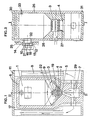
- Fig. 1 is a central sectional view along line I-I in Fig. 2 through a furnace in accordance with the invention.
- Fig. 2 is a corresponding central cross-sectional view along line II-II in Fig. 1 through the lower furnace part, the outer furnace parts having been removed.
- Fig. 3 is a sectional view along line I-I in Fig. 2 and line III-III in Fig. 4 through the draft-air supply means,
- Fig. 4 is a sectional view along line II-II in Fig. 1 and line IV-IV in Fig. 3 through the same draft-air supply means, and
- Fig. 5 illustrates on an enlarged scale a vertical sectional view through the fuel-feed lid and adjoining parts of the fuel supply opening of the furnace.
- The furnace illustrated in the drawing comprises an interior part which is designated genelrally by
numeral 6 and which is made from a heat-resistant material, such as ceramics, and anexterior part 11 enclosing the interior part and containing an exhaust channel system which, together with the water jacket 13 surrounding the exhaust channel system forms a heat-exchange system for extraction of thermal energy from the furnace. Between theinterior part 6 and theexterior part 11 is arranged alayer 17 of insulating material. In accordance with the embodiment illustrated, theinterior part 6 comprises two molded sections which are partitioned along plane II-II in Fig. 1. Preferably, these two halves are of symmetrical configuration, having anupper cavity portion 1 forming the fule storage vessel, and alower cavity part 7 forming the combustion chamber. - At its lower part the fuel storage vessel presents a sloping bottom which is covered by preferably
removable bottom slabs 4, which likewise preferably consist of a ceramics or any other heat-resistant material. The inclination angle of thebottom slabs 4 preferably is equal to or larger than the angle of repose of the fule material and the opposite edges of the slabs are spaced mutually apart so that a gap is formed between them. The gap serves as an exhaust-gas opening 5 which in the subject case also serves as the burner opening. The ends ofpart 6 which are turned towards each other are covered by end wall slabs 26a and 26b which preferably also are made of ceramics or some other heat-resistant material. - Centrally inside the bottom part of the fuel storage vessel the
interior part 6 is formed with apocket 27 into which is inserted a draft-air supply means, the latter likewise being made from a heat-resistant material, preferably ceramics. In accordance with the embodiment illustrated in the drawings the draft-air supply means 3, which preferably is removable, has an essentially parallelepiped configuration and covers the bruner opening 5 as well as the adjoining portions of the sloping bottom slabs orplane 4. Thelower faces 3a of the draft-air supply means extend closely alongside thebottom planes 4 whereby a comparatively small gap 2 is formed between thefaces 3a and the planes. A number of draft-air bores 24 communcating the interior draft-air channel 28 of the draft-air supply means with the gap 2, open in thelower faces 3a. A number of additional draft-air bores 23 also open above the gap 2 and, at a yet higher level, open further draft-air bores 19. Consequently, all draft-air bores form air-intake openings for supply of air to thecombustion zone 9. As is most clearly apparent from Fig. 3 some portions of the draft-air supply means are positioned above all air intake openings so as to efficiently prevent any combustion material which may fall from the fuel storage vessel from obstructing the air-intake openings. - In accordance with the shown embodiment the draft-air supply means has a parallelepiped configuration. This is a preferable configuration but obviously the invention is not restricted to this shape.
- Because the
faces 3a of the draft-air supply means as well as thefaces 3b thereabove are turned downwards these faces as such form the portions covering the associated openings. The upper air-intake openings 19 are covered by separate eaves-like projections 20. Thefaces - In accordance with the embodiment shown, the
faces 3a of the draft air supply means are essentially parallel with the slopingplanes 4 but obviously it is within the scope of the invention to vary the spacing somewhat between the sloping planes and the draft-air supply means, should this be required in view of particular fuels or the heat extraction from the furnace. Thecombustion chamber 7 likewise communicates with the exhaust-gas channel system 8 viaconnection channels 29. - At its upper part the furnace is covered by a
top slab 30 and at its base it is supported on abottom slab 31. In Fig. 2 only a part of the jacket system of the furnace is illustrated, more precisely the part surrounding the fuel supply opening 32 which may be closed by means of a fuel-feed lid 10. The fuel-feed opening 32 is surrounded by aflange 14 forming an inner sealing edge against the fuel-feed lid. The jacket system of the furnace also has anouter flange 12, forming an outer sealing edge against the lid. Between the interior portion of the furnace and the outer jacket system thereof there is agap 25 in communication with the furnace exhaust-gas channel system. - The construction of the fuel-feed lid is clearly apparent from Fig. 5, wherein the closed position of the lid is illustrated in continuous lines and its open position in discontinuous lines. The fuel-feed lid consist of two telescopically
movable portions compression springs 21 are held between these end walls. The inner portion is provided with alid plate 10e. By means of a packing 10f thelid plate 10e seals against theinner flange 14 and by means of a packing 10g theend wall 10d seals against theouter flange 12, as mentioned previously. Owing to the mutual movability of the two lids portions the latter provide an efficient seal against their associated flange, also in case the spacing between the end edges of the flanges should vary for some reason. To close the lid theinner flange 14 is moved first and theouter flange 12 thereafter to the closed positions. Also in the closed position of the lid the space 15 surrounding the lid maintains communication with the exhaust-gas canal system 25 of the furnace. The lid plane formed by thelid end wall 10d is designated byreference 18 on the drawings and the lid plane formed by thelid end wall 10e is designated by 16. - By
numeral references 33 is designated a valve by means of which the upper part of the fuel storage vessel may communicate with the exhaust gas channel system of the furnace. This may be the case when the furnace operation is initiated. However,valve 33 preferably is maintained in closed position when the furnace is in operation. - In operation of the furnace, biological fuel present in the
fuel storage vessel 1 is pyrolysed so as to form a gas which is forced downwards by its low atmospheric over-pressure through the burner opening 5 while being combusted and at the same time pre-heated air is being supplied from the draft-air supply means 3. Thefuel storage vessel 1, thecombustion zone 9, the draft-air supply tube 3, the slopingplanes 4 and thesecondary combustion chamber 7 together with the ashes-collection cavity pertaining thereto all preferably are made from a ceramics material as mentioned in the aforegoing. The exhaust gases preferably are transported insideair gap 25 surrounding the ceramics part. The draft tube placed over theburner opening 5 is located in the hot combustion zone and consequently it will be heated to a high temperature. The draft-air which is supplied by means of a preferably adjustable fan, not shown in the drawings, and which passes through thevarious openings draft tube 3 for the draft-air, turbulent combustion is created. - Part of the heat generated during the combustion finds it way upwards inside the fuel storage vessel, whereby the fuel is pyrolysed and gas is produced. Also when the heat-extraction is low the heat inside the
combustion zone 9 is sufficient to generate gases to an adequate degree. The combustion of gas travelling downwards essentially is the form of combustion of aldehyde. Aldehyde combustion oxidizes hydrocarbons by way of aldehyde into CO₂ and H₂O. Aldehyde combustion generates the cleanest exhaust gases. - The portion of the fuel storage vessel that is positioned above the
combustion zone 9 forms an upwardly closed vessel in the course of the process, provided that thevalve 33 is closed, and consequently gas can only be emitted downwards through theburner opening 5. In the course of the combustion process the fuel storage simultaneously forms a gas bell, wherein generated gas accumulates at a slight overpressure relatively to the surrounding atmosphere prior to its combustion and wherein the gas in the upper part of the fuel storage vessel will not be combustible on account of the poor oxygenation. When gas is generated from the fuel the volume of the gas increases and as a result a slight over-pressure is formed in the fuel storage vessel. This pressure combines with the pressure of the draft-air supply fan so as to pressurize the fuel storage vessel as required in order to force the gas downwards. Because the fuel storage vessel is pressurized it needs to be sealed. This requirement is met in that, as mentioned before, the fuel-feed lid is formed with double lid walls, each one having a sealing function. Any gas that may pass the sealing of the inner lid is sucked out through the fume exhaust. Owing to this arrangemnet, poisonous gases do not end up in the environment. During refuel, when the fuel-feed lid is open, fumes are prevented from seeping out into the environment, because these gases are evacuated by way of thefree space 25 between the inner and outer seals and are transferred further to the fume exhaust of the furnace. - When the process has progressed to the point where no more gas is generated, charcoal remains, if wood has been used as fuel. This charcoal is consumed continuously as draft-air is being supplied. The combustion of the charcoal takes place in two steps, first 2C² + O² = 2CO + heat, thereafter 2CO + O² + heat. At this stage of the process, new fuel is supplied if the heating is to continue. The biological-fuel furnace preferably operates continuously, and the heat extraction could be varied in accordance with the rotational speed of the fan supplying air to the draft-air supply means 3 from low extraction to high extraction, while maintaining purity of combustion and a high degree of efficiency. Owing to the angle of
inclination 22 of the bottom part of the fuel storage vessel the fuel material is efficiently urged to collapse downwards. This material could be charcoal and ashes. The sloping bottom part also forms a burner opening the dimensions of which can easily be adjusted to the capacity desired for the device. The sloping planes which are made from a heat resistant material, preferably a ceramics material, and which are replaceable, preferably are insulated from their support faces in order to retain the generated heat. This is of consideral importance to obtain good combustion results. Thevalve 33 provided in thefuel storage vessel 1 preferably is maintained in an open position during the starting-up stage, whereby the fumes will travel directly into the fume outlet. In this way the start-up is facilitated. During operation, this valve preferably is maintained in a closed position. The valve may also be opened while the device is being refueled, which contributes to preventing fumes from reaching the environment. Gas generated from thefuel storage vessel 1 is mixed with pre-heated air from the draft-air supply means 3 and is combusted downwards through theburner opening 5 into thesecondary combustion chamber 7 underneath. This space also serves as an ashes collection chamber. After combustion, the hot gases flow from thesecondary combustion chamber 7 to theheat exchanger 8, wherein the thermal energy is utilized in the customary way in the water jacket 13, whereupon the exhaust gases proceed upwards.
Claims (14)
- A furnace for biological fuels, comprising a fuel storage vessel (1) with a closable top, a fuel-feed lid (10) at the furnace top, and an exhaust-gas opening (5) at the bottom of the fuel storage vessel in order to create downwardly directed combustion, whereby the bottom (4) of the fuel storage vessel (1) slopes towards the exhaust-gas opening, said exhaust-gas opening (5) which also serves as the burner opening, being covered by a draft-air supply means (3) which along a part (3a) of its outer peripheri extends closely alongside the part of the sloping bottom (4) of the fuel storage vessel that is closest to the burner opening, an adjustable supply air fan being provided upstreams of the draft-air supply means, characterized in that said draft-air supply means (3) further comprises both downwardly directed draft-air channels (24) which open into the gap (2) formed between the draft-air supply means and the fuel storage vessel bottom, and laterally directed upper draft-air channels (19, 23).
- A biological fuel furnace as claimed in claim 1, characterized in that the draft-air supply means has portions projecting over the outlet mouths of the draft-air channels.
- A biological fuel furnace as claimed in claim 2, characterized in that the draft-air supply means (3) is a hollow body which is removably placed in a pocket (27) formed in the bottom part of the fuel storage vessel and which hollow body is made from a heat-resistant material, preferably ceramics.
- A biological fuel furnace as claimed in any one of the preceding claims, characterized in that it is provided with a combustion chamber (7) positioned after the gas exhaust opening (5) at the bottom of the fuel storage vessel.
- A biological fuel furnace as claimed in any one of the preceding claims, characterized in that a valve (33) is provided in the upper part of the fuel storage vessel in order to selectively interconnect this part of the fuel storage vessel with the exhaust channel system of the furnace.
- A biological fuel furnace as claimed in any one of the preceding claims, characterized in that the faces (3c, 3d) of the draft-air supply means (3) which are turned upwards slope downwards towards the bottom (4) of the fuel storage vessel.
- A biological fuel furnace as claimed in any one of the preceding claims, characterized in that the exhaust channel system of the furnace communicates with the refueling opening of the furnace which may be exposed by means of the refueling lid (10), at least in the opened position of the latter, in order to receive gas flowing from the fuel storage vessel during refueling.
- A biological fuel furnace as claimed in claim 7, characterized in that the fuel-feed lid has both an inner wall (14) which is sealed against the fuel storage vessel and an outer wall (12) which is sealed against a portion of the furnace which is positioned outside the fuel storage vessel, for instance a heat exchange part, whereby communication is established with the exhaust channel system in the gap (25) formed between said two walls.
- A biological fuel furnace as claimed in claim 8, characterized in that the gap (25) intermediate the interior and exterior sealing walls continuosly communicates with the exhaust channel system, i.e. independently on whether the fuel-feed lid is open or closed.
- A biological fuel furnace as claimed in any one of claims 7-9, characterized in that the two sealing walls of the fuel-feed lid are movable relatively to one another against the action of a spring in order to provide an efficient sealing effect independently of any variations in the spacing between the interior and exterior sealing means with which the lid cooperates in the closed position.
- A biological fuel furnace as claimed in any one of the preceding claims, characterized in that its interior components, i.e. the fuel storage vessel and the combustion chamber part consist of molded bodies of a ceramics material which are assembled into a unit.
- A biological fuel furnace as claimed in any one of the preceding claims, characterized in that the sloping planes (4) in the bottom part of the fuel storage vessel (1) are formed by removable ceramics slabs the facing bottom edges of which form the laterally limiting means of the burner opening (5) and thus determine the size of the burner opening.
- A biological fuel furnace as claimed in claim 2, 3 and 6, characterized in that the draft-air supply means (3) is in the form of a horizontal parallelepiped body in which draft-air supply openings (23, 24) are formed, at least in the faces (3b, 3a) that are turned downwards.
- A biological fuel furnace as claimed in claim 13, characterized in that the draft-air inlet openings (19) which are provided at the upper part of the draft-air supply means (3), are covered from above by eaves-like projections (20).
Applications Claiming Priority (4)
| Application Number | Priority Date | Filing Date | Title |
|---|---|---|---|
| SE8804032 | 1988-11-08 | ||
| SE19888804032A SE8804032D0 (en) | 1988-11-08 | 1988-11-08 | APPLICATION FOR COMBUSTION OF THE FIXED BRAZENAL BENEFITS |
| PCT/SE1989/000637 WO1990005269A1 (en) | 1988-11-08 | 1989-11-08 | Furnace for solid fuels |
| CA002034773A CA2034773C (en) | 1988-11-08 | 1991-01-23 | Solid fuel downdraft furnace |
Publications (2)
| Publication Number | Publication Date |
|---|---|
| EP0442931A1 EP0442931A1 (en) | 1991-08-28 |
| EP0442931B1 true EP0442931B1 (en) | 1994-06-01 |
Family
ID=25674455
Family Applications (1)
| Application Number | Title | Priority Date | Filing Date |
|---|---|---|---|
| EP89912515A Expired - Lifetime EP0442931B1 (en) | 1988-11-08 | 1989-11-08 | Furnace for solid fuels |
Country Status (10)
| Country | Link |
|---|---|
| US (1) | US5247892A (en) |
| EP (1) | EP0442931B1 (en) |
| AT (1) | ATE106523T1 (en) |
| AU (1) | AU4508289A (en) |
| CA (1) | CA2034773C (en) |
| DE (1) | DE68915775T2 (en) |
| FI (1) | FI92954C (en) |
| RU (1) | RU2005958C1 (en) |
| SE (1) | SE8804032D0 (en) |
| WO (1) | WO1990005269A1 (en) |
Families Citing this family (3)
| Publication number | Priority date | Publication date | Assignee | Title |
|---|---|---|---|---|
| NL8902749A (en) * | 1989-11-07 | 1991-06-03 | Leonardus Mathijs Marie Nevels | METHOD FOR COMBUSTION OF VARIOUS WASTE MATERIAL, INCLUDING OVEN, AND UNIVERSAL WASTE COMBUSTION SYSTEM WITH NUMBER OF SUCH OVENS. |
| DE4230311C1 (en) * | 1992-09-10 | 1993-12-09 | Wamsler Umwelttechnik Gmbh | Process and incinerator for incinerating waste |
| DE19826492A1 (en) * | 1998-06-13 | 1999-12-16 | Ebert Jens | Wood gasification boiler |
Family Cites Families (11)
| Publication number | Priority date | Publication date | Assignee | Title |
|---|---|---|---|---|
| US2337053A (en) * | 1939-03-06 | 1943-12-21 | James H Langley | Furnace |
| US4479481A (en) * | 1981-08-13 | 1984-10-30 | Ingersoll Charles S | Wood fuel heating apparatus and combustion process |
| FR2516209A1 (en) * | 1981-11-10 | 1983-05-13 | Hays Claude | Inverted-combustion hot water generator - has grille of refractory bricks above secondary combustion chamber over which hot gases pass |
| EP0084852A3 (en) * | 1982-01-26 | 1983-09-14 | UNICAL S.p.A. | Solid fuel steel construction boiler for domestic heating applications |
| US4441436A (en) * | 1982-10-27 | 1984-04-10 | Takumi Noma | Solid fuel burning methods and apparatus |
| US4471702A (en) * | 1983-07-11 | 1984-09-18 | Mckinlay Bruce A | Apparatus for burning waste material |
| US4531464A (en) * | 1984-07-20 | 1985-07-30 | Eshland Enterprises, Inc. | Particle fuel diversion structure |
| FR2583148A1 (en) * | 1985-06-10 | 1986-12-12 | Recurt Eric | Anticorrosion and anticondensation wood-fired boiler with inverted flame |
| FR2583503B1 (en) * | 1985-06-18 | 1990-01-12 | Barre Veronique | REVERSE OR HORIZONTAL COMBUSTION BOILER |
| FR2592944A1 (en) * | 1986-01-13 | 1987-07-17 | Etude Applic Gle Elements Meca | Solid-fuel boiler and more particularly wood-fired boiler |
| AU594181B2 (en) * | 1986-08-08 | 1990-03-01 | Clinton Badger Pike | Furnace |
-
1988
- 1988-11-08 SE SE19888804032A patent/SE8804032D0/en unknown
-
1989
- 1989-11-08 EP EP89912515A patent/EP0442931B1/en not_active Expired - Lifetime
- 1989-11-08 US US07/689,811 patent/US5247892A/en not_active Expired - Fee Related
- 1989-11-08 WO PCT/SE1989/000637 patent/WO1990005269A1/en not_active Ceased
- 1989-11-08 DE DE68915775T patent/DE68915775T2/en not_active Expired - Fee Related
- 1989-11-08 AT AT89912515T patent/ATE106523T1/en not_active IP Right Cessation
- 1989-11-08 AU AU45082/89A patent/AU4508289A/en not_active Abandoned
-
1991
- 1991-01-23 CA CA002034773A patent/CA2034773C/en not_active Expired - Fee Related
- 1991-05-07 FI FI912201A patent/FI92954C/en active
- 1991-05-08 RU SU914895669A patent/RU2005958C1/en active
Also Published As
| Publication number | Publication date |
|---|---|
| FI92954B (en) | 1994-10-14 |
| AU4508289A (en) | 1990-05-28 |
| DE68915775T2 (en) | 1995-01-05 |
| EP0442931A1 (en) | 1991-08-28 |
| DE68915775D1 (en) | 1994-07-07 |
| RU2005958C1 (en) | 1994-01-15 |
| ATE106523T1 (en) | 1994-06-15 |
| US5247892A (en) | 1993-09-28 |
| FI912201A0 (en) | 1991-05-07 |
| FI92954C (en) | 1995-01-25 |
| CA2034773C (en) | 1998-11-10 |
| CA2034773A1 (en) | 1992-07-24 |
| WO1990005269A1 (en) | 1990-05-17 |
| SE8804032D0 (en) | 1988-11-08 |
Similar Documents
| Publication | Publication Date | Title |
|---|---|---|
| US4565184A (en) | Combustible particulate fuel heater | |
| US4856491A (en) | High efficiency solid fuel burning stove | |
| US4646712A (en) | Solid fuel heating appliances | |
| US20110232622A1 (en) | Wood fired boiler | |
| US4397293A (en) | Heating apparatus comprising a heat recovery apparatus | |
| US4466358A (en) | Solid fuel warm air furnace | |
| GB2222671A (en) | Control of fuel supply to gas fire | |
| US4409955A (en) | Solid fuel warm air furnace | |
| RU2134838C1 (en) | Furnace | |
| US5413089A (en) | Wood and coal burning stove | |
| US4252104A (en) | Space heaters | |
| US4510918A (en) | Woodburning heating apparatus | |
| US4207860A (en) | Wood-coal heating unit | |
| US5247892A (en) | Furnace for solid fuels | |
| US4506653A (en) | Combustion method and apparatus | |
| US5201307A (en) | Insulated firebox for swimming pool or spa heaters for reduction of smoke or odor | |
| CA1235969A (en) | Solid fuel heating appliances | |
| DK155463B (en) | STAINLESS STEEL BOAT, ISAIR FOR WOOD | |
| US6026805A (en) | Heating apparatus | |
| EP0065880A1 (en) | Heater assemblies | |
| CN209782717U (en) | Isolated air flue gas inlet combustion furnace | |
| US1380151A (en) | Combined gas and coal range | |
| BG113671A (en) | BOTTOM BURNING WOOD BURNING HEATER (STOVE) COMBINED WITH THERMALLY INSULATED INTERIOR CHIMNEY (HEATRISER) | |
| EP0155045B1 (en) | A stove for combusting both liquid and solid fuels | |
| JPS6124830Y2 (en) |
Legal Events
| Date | Code | Title | Description |
|---|---|---|---|
| PUAI | Public reference made under article 153(3) epc to a published international application that has entered the european phase |
Free format text: ORIGINAL CODE: 0009012 |
|
| 17P | Request for examination filed |
Effective date: 19910506 |
|
| AK | Designated contracting states |
Kind code of ref document: A1 Designated state(s): AT BE CH DE FR GB IT LI LU NL SE |
|
| 17Q | First examination report despatched |
Effective date: 19920713 |
|
| GRAA | (expected) grant |
Free format text: ORIGINAL CODE: 0009210 |
|
| AK | Designated contracting states |
Kind code of ref document: B1 Designated state(s): AT BE CH DE FR GB IT LI LU NL SE |
|
| PG25 | Lapsed in a contracting state [announced via postgrant information from national office to epo] |
Ref country code: IT Free format text: LAPSE BECAUSE OF FAILURE TO SUBMIT A TRANSLATION OF THE DESCRIPTION OR TO PAY THE FEE WITHIN THE PRE;WARNING: LAPSES OF ITALIAN PATENTS WITH EFFECTIVE DATE BEFORE 2007 MAY HAVE OCCURRED AT ANY TIME BEFORE 2007. THE CORRECT EFFECTIVE DATE MAY BE DIFFERENT FROM THE ONE RECORDED.SCRIBED TIME-LIMIT Effective date: 19940601 Ref country code: FR Effective date: 19940601 Ref country code: NL Effective date: 19940601 Ref country code: BE Effective date: 19940601 |
|
| REF | Corresponds to: |
Ref document number: 106523 Country of ref document: AT Date of ref document: 19940615 Kind code of ref document: T |
|
| REF | Corresponds to: |
Ref document number: 68915775 Country of ref document: DE Date of ref document: 19940707 |
|
| EN | Fr: translation not filed | ||
| PG25 | Lapsed in a contracting state [announced via postgrant information from national office to epo] |
Ref country code: GB Effective date: 19941108 |
|
| NLV1 | Nl: lapsed or annulled due to failure to fulfill the requirements of art. 29p and 29m of the patents act | ||
| PG25 | Lapsed in a contracting state [announced via postgrant information from national office to epo] |
Ref country code: LU Free format text: LAPSE BECAUSE OF NON-PAYMENT OF DUE FEES Effective date: 19941130 |
|
| EAL | Se: european patent in force in sweden |
Ref document number: 89912515.7 |
|
| PLBE | No opposition filed within time limit |
Free format text: ORIGINAL CODE: 0009261 |
|
| STAA | Information on the status of an ep patent application or granted ep patent |
Free format text: STATUS: NO OPPOSITION FILED WITHIN TIME LIMIT |
|
| 26N | No opposition filed | ||
| GBPC | Gb: european patent ceased through non-payment of renewal fee |
Effective date: 19941108 |
|
| PGFP | Annual fee paid to national office [announced via postgrant information from national office to epo] |
Ref country code: CH Payment date: 19991103 Year of fee payment: 11 |
|
| PGFP | Annual fee paid to national office [announced via postgrant information from national office to epo] |
Ref country code: AT Payment date: 19991105 Year of fee payment: 11 |
|
| PGFP | Annual fee paid to national office [announced via postgrant information from national office to epo] |
Ref country code: DE Payment date: 19991123 Year of fee payment: 11 |
|
| PG25 | Lapsed in a contracting state [announced via postgrant information from national office to epo] |
Ref country code: AT Free format text: LAPSE BECAUSE OF NON-PAYMENT OF DUE FEES Effective date: 20001108 |
|
| PG25 | Lapsed in a contracting state [announced via postgrant information from national office to epo] |
Ref country code: CH Free format text: LAPSE BECAUSE OF NON-PAYMENT OF DUE FEES Effective date: 20001130 Ref country code: LI Free format text: LAPSE BECAUSE OF NON-PAYMENT OF DUE FEES Effective date: 20001130 |
|
| REG | Reference to a national code |
Ref country code: CH Ref legal event code: PL |
|
| PG25 | Lapsed in a contracting state [announced via postgrant information from national office to epo] |
Ref country code: DE Free format text: LAPSE BECAUSE OF NON-PAYMENT OF DUE FEES Effective date: 20010801 |
|
| PGFP | Annual fee paid to national office [announced via postgrant information from national office to epo] |
Ref country code: SE Payment date: 20011116 Year of fee payment: 13 |
|
| PG25 | Lapsed in a contracting state [announced via postgrant information from national office to epo] |
Ref country code: SE Free format text: LAPSE BECAUSE OF NON-PAYMENT OF DUE FEES Effective date: 20021109 |
|
| EUG | Se: european patent has lapsed |