EP0443065B1 - Double passenger seat - Google Patents
Double passenger seat Download PDFInfo
- Publication number
- EP0443065B1 EP0443065B1 EP90103398A EP90103398A EP0443065B1 EP 0443065 B1 EP0443065 B1 EP 0443065B1 EP 90103398 A EP90103398 A EP 90103398A EP 90103398 A EP90103398 A EP 90103398A EP 0443065 B1 EP0443065 B1 EP 0443065B1
- Authority
- EP
- European Patent Office
- Prior art keywords
- seat
- passenger seat
- profile
- box beam
- double passenger
- Prior art date
- Legal status (The legal status is an assumption and is not a legal conclusion. Google has not performed a legal analysis and makes no representation as to the accuracy of the status listed.)
- Expired - Lifetime
Links
- 238000009434 installation Methods 0.000 claims description 2
- XLYOFNOQVPJJNP-UHFFFAOYSA-N water Substances O XLYOFNOQVPJJNP-UHFFFAOYSA-N 0.000 claims description 2
- 238000010276 construction Methods 0.000 description 13
- 125000006850 spacer group Chemical group 0.000 description 3
- 230000008093 supporting effect Effects 0.000 description 2
- 238000011109 contamination Methods 0.000 description 1
- 230000006378 damage Effects 0.000 description 1
- 238000006073 displacement reaction Methods 0.000 description 1
Images
Classifications
-
- B—PERFORMING OPERATIONS; TRANSPORTING
- B60—VEHICLES IN GENERAL
- B60N—SEATS SPECIALLY ADAPTED FOR VEHICLES; VEHICLE PASSENGER ACCOMMODATION NOT OTHERWISE PROVIDED FOR
- B60N2/00—Seats specially adapted for vehicles; Arrangement or mounting of seats in vehicles
- B60N2/24—Seats specially adapted for vehicles; Arrangement or mounting of seats in vehicles for particular purposes or particular vehicles
- B60N2/242—Bus seats
Definitions
- the invention relates to a double passenger seat for installation in land, water and aircraft, formed from a seat base on which two seat parts and each with rigidly or pivotally connected back parts are arranged, one of the seat parts transverse on a pair of linear adjustment rails is displaceable to the seat direction and the seat underframe consists of support feet on which a crossbar formed from two spaced-apart profile bars or from a correspondingly shaped profile plate is fastened, on which the seat parts may have to be arranged via mounting plates (see, for example, EP-B- 0 263 189).
- passenger seats In addition to the conditions for normal seating, such as seating comfort and an attractive exterior, passenger seats must also be “operationally safe”. This means that these passenger seats, which are subject to much tougher stresses than normal seating furniture, must be extremely stable, that they must still be able to absorb impact energy without splinters, that they must still be rattle-free even after long periods of operation, and that they must in spite of everything, they must be light in weight. Another important requirement is the economic manufacturability of the passenger seats, as well as their economical operation, through the possibility of replacing wearing parts. These passenger seats should also be easy to install in the vehicles in question and should be adaptable to the space there or to the desired space. Another requirement resulting from the necessity for economy and thus for the production of large quantities is that the passenger seats should have the smallest possible volume, so that they are to be dispatched as much as possible into individual parts.
- the seats should also be designed so that, for economic reasons, they can be arranged as close as possible to one another, but that despite this tight arrangement there is still enough legroom for comfortable sitting.
- the height of the base on which the seat parts are attached is decisive for this legroom. Since the height of the seat must follow the anatomical conditions, on the other hand, the seat parts must not fall below a certain upholstery height, only the possibility to improve the legroom or to maximize the free height remaining under the seat base frame with the seat frames of the type described above make transverse parts of the seat base as flat as possible.
- the height of the adjustment rail must also be taken into account, which allows one of the seat parts to be moved transversely to the seat direction, which is to be attached between the top of the base frame and the underside of the seat part or the corresponding mounting plate.
- DE-OS 30 22 640 A very good solution that meets all of the above conditions is given in DE-OS 30 22 640.
- a pair of spaced-apart, spanning the support legs profile bars which are double C-shaped in cross section. This creates two guide grooves for connecting screws, so that both the support feet can be attached to the profile bars at almost any distance from each other, as well as the seat parts are easy to fix, again at any distance from each other.
- the two profile bars can also be connected by an interposed, supporting plate as a spacer.
- a disadvantage of this construction is the height of the profile bars or profile plate, which is necessary for reasons of stability.
- the object of the invention is to provide a way in which these profile bars or this profile plate can be formed so that the overall construction - with or without an adjustment rail - has the lowest possible height or that the construction provides the greatest possible legroom without the necessary stability is affected.
- the profile bars or the profile plate have a longitudinally extending, self-contained box spar, which is used to mount the seat parts with at least one for attachment to the support feet and with another, located approximately on the same level serving connecting rail is connected.
- the connecting rails can expediently again have a C-shaped cross section.
- the profile bars or the profile plate can have further fastening options, be it as a connecting rail, as an elongated hole or through-hole, in order, if necessary, to enable a special assembly of the seats or additional seat devices via additional connecting links.
- the C-shaped profile parts are arranged one above the other, but lying next to each other at approximately the same height, so that the height of a profile part is saved.
- the height of the box spar determines its section modulus and a certain section modulus must not be undercut in order not to impair the stability of the overall construction, the height of the box spar should be clear in order not to have to make the profile bars or the profile plate too massive
- a multiple seat arrangement for buses in which the aisle seat can be moved transversely to the seat direction.
- two longitudinal guides are provided which are parallel to each other and each made up of two rails, namely a seat rail and a lower rail.
- the longitudinal guides and two beams running in the direction of the seat together form a seat support frame.
- the beams are designed as a U-profile, the bottom rail as a multi-angled profile. Such a design improves the mechanical strength, but requires space in the vertical direction.
- a passenger seat arrangement which is arranged on a profile plate.
- the profile plate has rail-shaped recesses at its ends for fastening the seats on the feet.
- the recesses are arranged one above the other in the vertical direction, which means that additional space is required in the vertical direction. exceed the height of the connecting profile parts, i.e. the connecting rails.
- This is also possible without further ado that the adjustment rails must also be attached to the connecting rail to which the seat parts are to be attached, so that now the box rail, without increasing the overall height of the construction, increases the height of the connecting rail plus the height the adjustment rail can have.
- the connecting rails can be attached to the underside of the box beam.
- the connecting rails the mounting surfaces of which can be arranged at any angle to the profile bar or profile plate plane, are attached laterally or on both sides of the box beam with its lower edge.
- the height of the box beam is expediently chosen to be greater than its width, this height should at least correspond to the height of the adjustment rail.
- the connecting rail used to assemble the seat parts is connected to a cover on the top, which surrounds an adjustment rail attached to the connecting rail. This not only covers the moving parts of the adjustment rail to avoid injuries, but also prevents contamination of the adjustment rail from functioning.
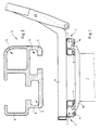
- the seat underframe of a passenger seat is formed from support feet (1), from profile bars (2) bridging the support feet (1) and from frame quadrilaterals (3) serving as mounting plates for the seat parts.
- Part of these approximately rectangular profile bars (2) is a box beam (4) which is connected on the underside to a connecting rail (5) which is approximately C-shaped in cross section.
- the connecting rail (5) has a channel (6) which is open at the bottom and into which grooved screws can be inserted, with which the profile bars (2) can be screwed onto a crossmember (19) of the support feet (1).
- a further connecting rail (8) of the same design is arranged, but with a channel (7) open at the top to the mounting rectangles (3).
- An adjustment rail can also be attached to the profile bars (2) by means of grooved screws to be inserted into this channel (7) (for the sake of clarity, these mounting screws are not shown), on which the mounting rectangles (3) are then screwed.
- spacers can of course also be screwed on if a displacement of the seat part via such an adjustment rail is not desired.
- a screwed-on adjustment rail or screwed-on spacers covering cover (9) is provided, which also protects the adjustment rail against dirt.
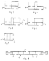
- FIG. 3 to 8 show different cross-sectional patterns for the profile bars (2).
- the connecting rails which are open to the support feet (1) are each designated by the reference number 5, and the connecting rails which are open at the top are designated by the reference number 8.
- Fig. 5 a sideways protruding flat rail (14) can still be seen, which can be used to attach additional seat parts.
- 7 also shows a possibility of also providing connecting rails (10, 11) on the side.
- Fig. 8 also shows a profile plate (12), the two connecting rails (5, 8) being connected to one another via a stiffened plate (13) and also further connection options (5, 8) being provided.
Landscapes
- Engineering & Computer Science (AREA)
- Aviation & Aerospace Engineering (AREA)
- Transportation (AREA)
- Mechanical Engineering (AREA)
- Seats For Vehicles (AREA)
- Organic Low-Molecular-Weight Compounds And Preparation Thereof (AREA)
- Bridges Or Land Bridges (AREA)
- Chair Legs, Seat Parts, And Backrests (AREA)
Abstract
Description
Die Erfindung betrifft einen Doppel-Fahrgastsitz zum Einbau in Land-, Wasser- und Luftfahrzeuge, gebildet aus einem Sitzuntergestell, auf dem zwei Sitzteile und jeweils mit ihnen starr oder verschwenkbar verbundene Rückenteile angeordnet sind, wobei eines der Sitzteile auf einem Paar geradlinig führender Verstellschienen quer zur Sitzrichtung verschiebbar ist und das Sitzuntergestell aus Stützfüßen besteht, auf denen ein aus zwei mit Abstand voneinander angeordneten Profilstäben oder aus einer entsprechend geformten Profilplatte gebildeter Querbügel befestigt ist, auf dem die Sitzteile gegebenenfalls über Montageplatten anzuordnen sind (s. zum Beispiel EP-B-0 263 189).The invention relates to a double passenger seat for installation in land, water and aircraft, formed from a seat base on which two seat parts and each with rigidly or pivotally connected back parts are arranged, one of the seat parts transverse on a pair of linear adjustment rails is displaceable to the seat direction and the seat underframe consists of support feet on which a crossbar formed from two spaced-apart profile bars or from a correspondingly shaped profile plate is fastened, on which the seat parts may have to be arranged via mounting plates (see, for example, EP-B- 0 263 189).
Fahrgastsitze müssen, über die Bedingungen für normale Sitzmöbel, wie Sitzkomfort und ansprechendes Äußere hinaus, auch "betriebssicher" sein. Das heißt, daß diese Fahrgastsitze, die ja wesentlich härteren Beanspruchungen als normale Sitzmöbel ausgesetzt sind, äußerst stabil sein müssen, daß sie trotzdem in der Lage sein müssen, Aufprallenergie splitterfrei nachgebend aufzunehmen, daß sie auch nach langen Betriebszeiten noch klapperfrei sein müssen und daß sie trotz allem nur ein geringes Gewicht aufweisen dürfen. Eine weitere wichtige Forderung ist die der wirtschaftlichen Herstellbarkeit der Fahrgastsitze, wie auch deren wirtschaftlicher Betrieb, durch die Möglichkeit der Auswechslung von Verschleißteilen. Auch sollen diese Fahrgastsitze in den betreffenden Fahrzeugen einfach zu montieren und den dortigen beziehungsweise den gewünschten Platzverhältnissen anzupassen sein. Eine weitere Forderung, die aus dem Zwang zur Wirtschaftlichkeit und damit zur Herstellung großer Stückzahlen resultiert, ist, daß die Fahrgastsitze ein möglichst geringes Volumen aufweisen sollen, daß sie also weitestgehend in Einzelteile zerlegt zu versenden sind.In addition to the conditions for normal seating, such as seating comfort and an attractive exterior, passenger seats must also be "operationally safe". This means that these passenger seats, which are subject to much tougher stresses than normal seating furniture, must be extremely stable, that they must still be able to absorb impact energy without splinters, that they must still be rattle-free even after long periods of operation, and that they must in spite of everything, they must be light in weight. Another important requirement is the economic manufacturability of the passenger seats, as well as their economical operation, through the possibility of replacing wearing parts. These passenger seats should also be easy to install in the vehicles in question and should be adaptable to the space there or to the desired space. Another requirement resulting from the necessity for economy and thus for the production of large quantities is that the passenger seats should have the smallest possible volume, so that they are to be dispatched as much as possible into individual parts.
Diesen gesamten Forderungen wurden die bisher bekannten Fahrgastsitze nicht gerecht. Unter Hintanstellung der anderen Forderungen wurden diese Fahrgastsitze vielmehr so stabil aufgebaut, daß sie mit Sicherheit über die gesamte Standzeit der Fahrzeugsitze den an sie gestellten Festigkeitsanforderungen genügten und auch nach langer Gebrauchsdauer noch klapperfrei waren. Daraus resultierten jedoch nicht nur teure, sondern auch verhältnismäßig schwere Fahrgastsitze, so daß die Fahrzeuge immer ein recht hohes Totgewicht mitschleppen mußten. Außerdem wurden äußerst kostenaufwendig jeweils den bestimmten Anforderungen angepaßte Fahrgastsitze gefertigt.The previously known passenger seats did not meet all of these requirements. With the other requirements put aside, these passenger seats were rather built so stably that they certainly met the strength requirements placed on them over the entire service life of the vehicle seats and were still rattle-free even after a long period of use. However, this not only resulted in expensive, but also relatively heavy passenger seats, so that the vehicles always had to carry a rather high dead weight. In addition, extremely costly passenger seats adapted to the specific requirements were manufactured.
Neben den oben angeführten Forderungen sollen die Sitze auch noch so gestaltet sein, daß sie zwar aus ökonomischen Gründen möglichst dicht hintereinander angeordnet werden können, daß jedoch trotz dieser dichten Anordnung noch genügend Beinfreiheit zum komfortablen Sitzen verbleibt. Maßgebend für diese Beinfreiheit ist die Höhe des Untergestells, auf dem die Sitzteile angebracht sind. Da die Höhe der Sitzfläche den anatomischen Gegebenheiten folgen muß, andererseits auch die Sitzteile eine bestimmte Polsterhöhe nicht unterschreiten dürfen, bleibt zur Verbesserung der Beinfreiheit beziehungsweise zur Maximierung der freien, unter dem Sitzuntergestell verbleibenden Höhe bei den Sitzgestellen der oben beschriebenen Art nur die Möglichkeit, die quer verlaufenden Teile des Sitzuntergestells möglichst flach auszubilden. Eine weitere Möglichkeit, unter Abkehr von der beschriebenen bewährten Art, wurde auch darin gesehen, zwischen den Stützfüßen nur einen mittleren Träger vorzusehen, der dann allerdings sehr stabil aufgebaut werden muß, um den übrigen Bedingungen genügen zu können. Insbesondere hat sich gezeigt, daß dieser mittlere Träger trotz stabiler Ausführung nicht dafür geeignet ist, die hohen Torsionskräfte, die bei einem Unfall auf ihn einwirken können, aufzunehmen. Es werden daher, bei modernen Fahrgastsitzen, stets zwei mit Abstand voneinander angeordnete, die Stützfüße überbrückende Konstruktionsteile oder eine entsprechend geformte Platte zum Aufbau der Sitzteile vorgesehen.In addition to the requirements mentioned above, the seats should also be designed so that, for economic reasons, they can be arranged as close as possible to one another, but that despite this tight arrangement there is still enough legroom for comfortable sitting. The height of the base on which the seat parts are attached is decisive for this legroom. Since the height of the seat must follow the anatomical conditions, on the other hand, the seat parts must not fall below a certain upholstery height, only the possibility to improve the legroom or to maximize the free height remaining under the seat base frame with the seat frames of the type described above make transverse parts of the seat base as flat as possible. A further possibility, while turning away from the proven type described, was also seen in providing only a central support between the support feet, which, however, then has to be constructed very stably in order to be able to meet the other conditions. In particular, it has been shown that, despite its sturdy design, this middle carrier is not suitable for absorbing the high torsional forces which can act on it in the event of an accident. In modern passenger seats, therefore, two spaced-apart structural parts bridging the support feet or a correspondingly shaped plate are always provided for the construction of the seat parts.
Bei der Berechnung der Höhe dieser Untergestelle ist auch noch die Höhe der Verstellschiene zu berücksichtigen, die es erlaubt, einen der Sitzteile quer zur Sitzrichtung zu verschieben, die also zwischen der Oberseite des Untergestells und der Unterseite des Sitzteils beziehungsweise der entsprechenden Montageplatte anzubringen ist.When calculating the height of these subframes, the height of the adjustment rail must also be taken into account, which allows one of the seat parts to be moved transversely to the seat direction, which is to be attached between the top of the base frame and the underside of the seat part or the corresponding mounting plate.
Eine sehr gute Lösung, die all den oben gestellten Bedingungen gerecht wird, ist in der DE-OS 30 22 640 angegeben. Vorgesehen sind hier ein Paar im Abstand voneinander angeordnete, die Stützfüße überbrückende Profilstäbe, die im Querschnitt doppel-C-förmig ausgebildet sind. Dadurch entstehen zwei Führungsnuten für Verbindungsschrauben, so daß sowohl die Stützfüße in nahezu beliebigem Abstand voneinander an den Profilstäben angebracht werden können, wie auch die Sitzteile unschwer, wiederum in beliebigem Abstand voneinander, zu befestigen sind. Die beiden Profilstäbe können auch durch eine zwischengefügte, mittragende Platte als Abstandhalter verbunden sein. Nachteilig macht sich bei dieser Konstruktion allerdings die Höhe der Profilstäbe beziehungsweise der Profilplatte bemerkbar, die jedoch aus Stabilitätsgründen notwendig ist.A very good solution that meets all of the above conditions is given in DE-OS 30 22 640. Provided here are a pair of spaced-apart, spanning the support legs profile bars, which are double C-shaped in cross section. This creates two guide grooves for connecting screws, so that both the support feet can be attached to the profile bars at almost any distance from each other, as well as the seat parts are easy to fix, again at any distance from each other. The two profile bars can also be connected by an interposed, supporting plate as a spacer. A disadvantage of this construction is the height of the profile bars or profile plate, which is necessary for reasons of stability.
Eine Verbesserung in dieser Hinsicht ist gegeben durch eine Konstruktion nach der EP-B-0 263 189, bei der die Stabilität der wiederum mit doppel-C-förmigen Nuten versehenen Profilstäbe dadurch herbeigeführt wird, daß die im Querschnitt C-förmigen Profilteile in jeweils einem Profilstab eingebettet sind, der zwei durchgehende, in sich geschlossene Kastenholme aufweist. Da die Stabilität dieser Profilstäbe beziehungsweise dieser Profilplatte durch die Kastenholme herbeigeführt wird, können sie bei gleicher Belastungsmöglichkeit niedriger aufgebaut sein. Allerdings müssen die Verstellschienen, ebenso wie bei der zuvor beschriebenen Konstruktion, auch hier noch auf den Profilstäben beziehungsweise auf der Profilplatte angeordnet werden, so daß sich die Höhe der Gesamtkonstruktion noch um die Höhe der Verstellschiene vergrößert beziehungsweise die Beinfreiheit entsprechend verringert wird.An improvement in this regard is given by a construction according to EP-B-0 263 189, in which the stability of the profile bars, which in turn are provided with double-C-shaped grooves, is brought about by the fact that the cross-sectionally C-shaped profile parts in one Profile bar are embedded, which has two continuous, self-contained box bars. Since the stability of these profile bars or this profile plate is brought about by the box spars, they can be constructed lower with the same load possibility. However, as with the construction described above, the adjustment rails must also be arranged here on the profile bars or on the profile plate, so that the height of the overall construction is increased by the height of the adjustment rail or the legroom is reduced accordingly.
Aufgabe der Erfindung ist es, eine Möglichkeit anzugeben, wie diese Profilstäbe beziehungsweise diese Profilplatte ausgebildet werden können, so daß die Gesamtkonstruktion - mit oder ohne Verstellschiene - eine möglichst geringe Höhe aufweist beziehungsweise daß die Konstruktion eine möglichst große Beinfreiheit gewährt, ohne daß die notwendige Stabilität beeinträchtigt wird.The object of the invention is to provide a way in which these profile bars or this profile plate can be formed so that the overall construction - with or without an adjustment rail - has the lowest possible height or that the construction provides the greatest possible legroom without the necessary stability is affected.
Erreicht wird dies in erfindungsgemäßer Weise dadurch, daß die Profilstäbe beziehungsweise die Profilplatte einen in Längsrichtung verlaufenden, in sich geschlossenen Kastenholm aufweisen, der mit mindestens einer zum Anbringen an den Stützfüßen dienenden und mit einer weiteren, etwa auf gleicher Ebene liegenden, zur Montage der Sitzteile dienenden Verbindungsschiene verbunden ist. Hierbei können die Verbindungsschienen, wie auch bei den bekannten Konstruktionen, zweckmäßigerweise wiederum einen C-förmigen Querschnitt aufweisen. Selbstverständlich können die Profilstäbe beziehungsweise die Profilplatte noch weitere Befestigungsmöglichkeiten, sei es nun als Verbindungsschiene, als Langloch oder Durchgangsloch aufweisen, um gegebenenfalls über Zusatz-Verbindungsglieder eine spezielle Montage der Sitze oder zusätzlicher Sitzeinrichtungen zu ermöglichen.This is achieved in a manner according to the invention in that the profile bars or the profile plate have a longitudinally extending, self-contained box spar, which is used to mount the seat parts with at least one for attachment to the support feet and with another, located approximately on the same level serving connecting rail is connected. Here, as in the known constructions, the connecting rails can expediently again have a C-shaped cross section. Of course, the profile bars or the profile plate can have further fastening options, be it as a connecting rail, as an elongated hole or through-hole, in order, if necessary, to enable a special assembly of the seats or additional seat devices via additional connecting links.
Nicht mehr also wie bei den bekannten Konstruktionen, werden die C-förmigen Profilteile übereinander angeordnet, sondern etwa auf gleicher Höhe liegend nebeneinander, so daß dadurch die Höhe eines Profilteils eingespart ist. Da jedoch die Höhe des Kastenholms sein Widerstandsmoment bestimmt und ein gewisses Widerstandsmoment, um die Stabilität der Gesamtkonstruktion nicht zu beeinträchtigen, nicht unterschritten werden darf, sollte, um die Profilstäbe beziehungsweise die Profilplatte nicht zu massiv ausführen zu müssen, die Höhe des Kastenholms deutlichNo longer as in the known constructions, the C-shaped profile parts are arranged one above the other, but lying next to each other at approximately the same height, so that the height of a profile part is saved. However, since the height of the box spar determines its section modulus and a certain section modulus must not be undercut in order not to impair the stability of the overall construction, the height of the box spar should be clear in order not to have to make the profile bars or the profile plate too massive
Aus der DE-A-3 147 045 ist eine Mehrfachsitzanordnung für Omnibusse bekannt, bei der der gangseitige Sitz quer zur Sitzrichtung verschoben werden kann. Hierzu sind zwei zueinander parallele und aus je zwei ineinander geführten Schienen, nämlich einer Sitzschiene und einer Unterschiene, zusammengesetzte Längsführungen vorhanden. Die Längsführungen und zwei in Sitzrichtung verlaufende Träger bilden zusammen einen Sitztragrahmen. Die Träger sind als U-Profil ausgebildet, die Unterschiene als mehrfach abgewinkeltes Profil. Durch eine solche Ausbildung wird zwar die mechanische Festigkeit verbessert, jedoch in senkrechter Richtung Raum benötigt.From DE-A-3 147 045 a multiple seat arrangement for buses is known, in which the aisle seat can be moved transversely to the seat direction. For this purpose, two longitudinal guides are provided which are parallel to each other and each made up of two rails, namely a seat rail and a lower rail. The longitudinal guides and two beams running in the direction of the seat together form a seat support frame. The beams are designed as a U-profile, the bottom rail as a multi-angled profile. Such a design improves the mechanical strength, but requires space in the vertical direction.
Aus der EP-A-0 330 594 ist eine Fahrgastsitzanordnung bekannt, welche auf einer Profilplatte angeordnet ist. Die Profilplatte weist an ihren Enden zur Befestigung der Sitze auf den Füßen schienenförmige Aussparungen auf. Die Aussparungen sind in senkrechter Richtung übereinander angeordnet, wodurch in senkrechter Richtung zusätzlicher Platz benötigt wird.
die Höhe der Verbindungs-Profilteile, also der Verbindungsschienen, übersteigen. Dies ist auch ohne weiteres dadurch möglich, daß ja auf der Verbindungsschiene, an der die Sitzteile anzubringen sind, auch noch die Verstellschienen angebracht werden müssen, so daß nun der Kastenholm, ohne die Gesamthöhe der Konstruktion zu vergrößern, die Höhe der Verbindungsschiene zuzüglich der Höhe der Verstellschiene aufweisen kann. Damit ergibt sich eine Gesamtkonstruktion, die zwar äußerst niedrig ist, also sehr viel Beinfreiheit zuläßt, die aber trotzdem den sonstigen Bedingungen, insbesondere hinsichtlich der notwendigen Stabilität, genügt.From EP-A-0 330 594 a passenger seat arrangement is known which is arranged on a profile plate. The profile plate has rail-shaped recesses at its ends for fastening the seats on the feet. The recesses are arranged one above the other in the vertical direction, which means that additional space is required in the vertical direction.
exceed the height of the connecting profile parts, i.e. the connecting rails. This is also possible without further ado that the adjustment rails must also be attached to the connecting rail to which the seat parts are to be attached, so that now the box rail, without increasing the overall height of the construction, increases the height of the connecting rail plus the height the adjustment rail can have. This results in an overall construction, which is extremely low, so that allows a lot of legroom, but which still satisfies the other conditions, in particular with regard to the necessary stability.
Insbesondere dann, wenn eine Profilplatte verwendet wird, wobei der plattenförmige Teil mittragend wirkt, können die Verbindungsschienen an der Unterseite des Kastenholms angebracht werden. Bei Profilstäben empfiehlt es sich jedoch, daß die Verbindungsschienen, deren Montageflächen übrigens in einem beliebigen Winkel zur Profilstab- beziehungsweise Profilplattenebene angeordnet sein können, seitlich oder beidseits des Kastenholms mit dessen Unterkante abschließend angebracht sind. Des oben angesprochenen Widerstandsmomentes wegen wird zweckmäßigerweise die Höhe des Kastenholms größer als seine Breite gewählt, wobei diese Höhe zumindest der Höhe der Verstellschiene entsprechen sollte. Als sehr zweckmäßig hat es sich schließlich noch erwiesen, daß die zur Montage der Sitzteile dienende Verbindungsschiene mit einer oberseitigen, eine auf der Verbindungsschiene angebrachte Verstellschiene ummantelnde Abdeckung, verbunden ist. Dadurch werden nicht nur die beweglichen Teile der Verstellschiene Verletzungen vermeidend abgedeckt, sondern es wird auch eine die Funktion dieser Verstellschiene beeinträchtigende Verschmutzung vermieden.In particular when a profile plate is used, the plate-shaped part having a supporting effect, the connecting rails can be attached to the underside of the box beam. In the case of profile bars, however, it is recommended that the connecting rails, the mounting surfaces of which can be arranged at any angle to the profile bar or profile plate plane, are attached laterally or on both sides of the box beam with its lower edge. For the resistance moment mentioned above, the height of the box beam is expediently chosen to be greater than its width, this height should at least correspond to the height of the adjustment rail. Finally, it has proven to be very expedient that the connecting rail used to assemble the seat parts is connected to a cover on the top, which surrounds an adjustment rail attached to the connecting rail. This not only covers the moving parts of the adjustment rail to avoid injuries, but also prevents contamination of the adjustment rail from functioning.
Auf der Zeichnung ist ein Ausführungsbeispiel der erfindungsgemäßen Konstruktion dargestellt, und zwar zeigen:
- Fig. 1
- die Teil-Seitenansicht eines derartigen Doppel-Fahrgastsitzes, die
- Fig. 2
- in vergrößerter Darstellung die Profilform eines Profilstabes, die
- Fig. 3
- bis
- Fig. 7
- verschiedene Querschnittsformen und
- Fig. 8
- eine Profilplatte.
- Fig. 1
- the partial side view of such a double passenger seat, the
- Fig. 2
- in an enlarged view the profile shape of a profile bar, the
- Fig. 3
- to
- Fig. 7
- different cross-sectional shapes and
- Fig. 8
- a profile plate.
Das Sitzuntergestell eines Fahrgastsitzes ist gebildet aus Stützfüßen (1), aus die Stützfüße (1) überbrückenden Profilstäben (2) sowie aus als Montageplatten für die Sitzteile dienenden Rahmenvierecken (3). Bestandteil dieser etwa rechteckigen Profilstäbe (2) ist ein Kastenholm (4), der an der Unterseite mit einer im Querschnitt etwa C-förmigen Verbindungsschiene (5) verbunden ist. Die Verbindungsschiene (5) weist einen nach unten offenen Kanal (6) auf, in den Nutenschrauben einfügbar sind, mit denen die Profilstäbe (2) auf einer Traverse (19) der Stützfüße (1) angeschraubt werden können. Neben dieser Verbindungsschiene (5) ist eine weitere gleichgestaltete Verbindungsschiene (8) angeordnet, jedoch mit einem nach oben zu den Montagevierecken (3) offenen Kanal (7). Mittels auch hier in diesen Kanal (7) einzufügender Nutenschrauben (der Übersichtlichkeit halber sind diese Befestigungsschrauben nicht eingezeichnet) kann eine Verstellschiene an den Profilstäben (2) befestigt werden, auf denen sodann die Montagevierecke (3) anzuschrauben sind. Statt einer Verstellschiene können selbstverständlich auch dann, wenn eine Verschiebung des Sitzteils über eine solche Verstellschiene nicht gewünscht wird, Abstandsstücke angeschraubt werden. Oberhalb der Verbindungsschiene ne (8) ist eine aufgeschraubte Verstellschiene oder aufgeschraubte Abstandsstücke ummantelnde Abdeckung (9) vorgesehen, die die Verstellschiene außerdem gegen Verschmutzung schützt.The seat underframe of a passenger seat is formed from support feet (1), from profile bars (2) bridging the support feet (1) and from frame quadrilaterals (3) serving as mounting plates for the seat parts. Part of these approximately rectangular profile bars (2) is a box beam (4) which is connected on the underside to a connecting rail (5) which is approximately C-shaped in cross section. The connecting rail (5) has a channel (6) which is open at the bottom and into which grooved screws can be inserted, with which the profile bars (2) can be screwed onto a crossmember (19) of the support feet (1). In addition to this connecting rail (5), a further connecting rail (8) of the same design is arranged, but with a channel (7) open at the top to the mounting rectangles (3). An adjustment rail can also be attached to the profile bars (2) by means of grooved screws to be inserted into this channel (7) (for the sake of clarity, these mounting screws are not shown), on which the mounting rectangles (3) are then screwed. Instead of an adjustment rail, spacers can of course also be screwed on if a displacement of the seat part via such an adjustment rail is not desired. Above the connecting rail ne (8), a screwed-on adjustment rail or screwed-on spacers covering cover (9) is provided, which also protects the adjustment rail against dirt.
Die Fig. 3 bis 8 zeigen verschiedene Querschnittsmuster für die Profilstäbe (2). Hierbei sind die zu den Stützfüßen (1) offenen Verbindungsschienen jeweils mit der Bezugsziffer 5, die nach oben offenen Verbindungsschienen mit der Bezugsziffer 8 bezeichnet. Bei Fig. 5 ist noch eine seitwärts abstehende Flachschiene (14) erkennbar, die zum Befestigen weiterer Sitzteile dienen kann. Die Fig. 7 zeigt darüber hinaus eine Möglichkeit, auch seitlich Verbindungsschienen (10, 11) vorzusehen. Schließlich zeigt Fig. 8 noch eine Profilplatte (12), wobei die beiden Verbindungsschienen (5, 8) über eine in sich versteifte Platte (13) miteinander verbunden und auch noch weitere Verbindungsmöglichkeiten (5, 8) vorgesehen sind.3 to 8 show different cross-sectional patterns for the profile bars (2). The connecting rails which are open to the support feet (1) are each designated by the
Claims (8)
- A double passenger seat for installation in land vehicles, water craft and aircraft, formed from a seat support structure on which are arranged two seat portions and back portions which are respectively rigidly or pivotably connected thereto, wherein one of the seat portions is displaceable transversely to the seat direction on a pair of rectilinearly extending adjustment rails and the seat support structure comprises support legs (1) on which is fixed a transverse yoke which is formed from two profile bars (2) arranged at a spacing from each other or from a suitably shaped profile plate (12) and on which the seat portions are to be arranged, possibly by way of mounting plates, characterised in that the profile bars (2) or the profile plate (12) have a box beam (4) which extends in the longitudinal direction and which is closed in itself and which is connected to at least one connecting bar (5) serving for mounting to the support legs (1) and to a further connecting bar (8, 10, 11) which is disposed approximately in the same plane and which serves for mounting the seat portions (rectangular frame members 3).
- A double passenger seat according to claim 1 characterised in that the connecting bars (5, 8, 10, 11) are of a C-shaped cross-section.
- A double passenger seat according to claim 1 characterised in that the connecting bars (5, 8) are disposed at the underside of the box beam (4).
- A double passenger seat according to claim 1 characterised in that the connecting bars (5, 8, 10, 11) are disposed in such a way as to terminate with the underside thereof laterally of the box beam (4).
- A double passenger seat according to claim 3 characterised in that the connecting bars (5, 8, 10, 11) are disposed in such a way as to terminate with the underside thereof on both sides of the box beam (4).
- A double passenger seat according to claim 1 characterised in that the height of the box beam (4) is greater than its width.
- A double passenger seat according to one or more of the preceding claims characterised in that the box beam (4) is at least of the height of the adjusting rail.
- A double passenger seat according to one or more of the preceding claims characterised in that the connecting bar (8) which serves for mounting the seat portions is connected to a top cover (9) which encloses an adjusting rail mounted on the connecting bar (8).
Priority Applications (6)
| Application Number | Priority Date | Filing Date | Title |
|---|---|---|---|
| AT90103398T ATE111037T1 (en) | 1990-02-22 | 1990-02-22 | DOUBLE PASSENGER SEAT. |
| ES90103398T ES2058631T3 (en) | 1990-02-22 | 1990-02-22 | DOUBLE SEAT OF OCCUPANTS. |
| DE59007065T DE59007065D1 (en) | 1990-02-22 | 1990-02-22 | Double passenger seat. |
| EP90103398A EP0443065B1 (en) | 1990-02-22 | 1990-02-22 | Double passenger seat |
| US07/541,065 US5098156A (en) | 1990-02-22 | 1990-06-20 | Double passenger seat support arrangement |
| JP3027317A JPH0542846A (en) | 1990-02-22 | 1991-02-21 | Two-seater seat for passengers |
Applications Claiming Priority (1)
| Application Number | Priority Date | Filing Date | Title |
|---|---|---|---|
| EP90103398A EP0443065B1 (en) | 1990-02-22 | 1990-02-22 | Double passenger seat |
Publications (2)
| Publication Number | Publication Date |
|---|---|
| EP0443065A1 EP0443065A1 (en) | 1991-08-28 |
| EP0443065B1 true EP0443065B1 (en) | 1994-09-07 |
Family
ID=8203678
Family Applications (1)
| Application Number | Title | Priority Date | Filing Date |
|---|---|---|---|
| EP90103398A Expired - Lifetime EP0443065B1 (en) | 1990-02-22 | 1990-02-22 | Double passenger seat |
Country Status (6)
| Country | Link |
|---|---|
| US (1) | US5098156A (en) |
| EP (1) | EP0443065B1 (en) |
| JP (1) | JPH0542846A (en) |
| AT (1) | ATE111037T1 (en) |
| DE (1) | DE59007065D1 (en) |
| ES (1) | ES2058631T3 (en) |
Cited By (1)
| Publication number | Priority date | Publication date | Assignee | Title |
|---|---|---|---|---|
| DE10064574C1 (en) * | 2000-12-22 | 2002-01-17 | Vogel Ind Gmbh | Vehicle seat, for bus or train, has seat element that slides on sub-frame and pivoting back rest with control unit, so that seat element slides forwards when back rest is pivoted backwards |
Families Citing this family (19)
| Publication number | Priority date | Publication date | Assignee | Title |
|---|---|---|---|---|
| DE9017470U1 (en) * | 1990-12-24 | 1991-03-14 | Ignaz Vogel Gmbh Und Co Kg - Fahrzeugsitze, 7500 Karlsruhe | Double passenger seat |
| DE4337939C2 (en) * | 1993-11-06 | 1997-06-05 | Keiper Recaro Gmbh Co | Vehicle seat, in particular passenger seat |
| CA2156971C (en) * | 1994-09-24 | 2001-08-21 | Richard C. Magnuson | Seat assembly for mass transit vehicle |
| DE19523014C2 (en) * | 1995-06-24 | 2000-07-27 | Sicosys Ag Hergiswil | Profile for fastening passenger seats |
| DE19709314C2 (en) * | 1997-03-07 | 1998-11-19 | Audi Ag | Seat base for a motor vehicle seat |
| DE19709315C2 (en) * | 1997-03-07 | 1998-11-19 | Audi Ag | Seat console for a motor vehicle seat |
| DE19912111C1 (en) * | 1999-03-18 | 2000-07-13 | Vogel Ind Gmbh | Passenger vehicle seat on crossbar uses crossbar undercut for conformably shaped projection on seat to engage undercut when inserted and be held there by holding element for stability. |
| AUPQ297099A0 (en) * | 1999-09-21 | 1999-10-14 | Camatic Pty. Limited | Seating system |
| US6913318B2 (en) * | 2002-12-03 | 2005-07-05 | Pride Mobility Products Corporation | Adjustable seat support for a wheelchair |
| JP5010117B2 (en) * | 2005-07-20 | 2012-08-29 | 株式会社神戸製鋼所 | Aluminum extruded hollow panel for automobile and manufacturing method thereof |
| JP4531671B2 (en) * | 2005-10-12 | 2010-08-25 | 株式会社神戸製鋼所 | Hollow panel and manufacturing method thereof |
| DE102008062113B4 (en) * | 2008-12-16 | 2020-01-23 | Zim Gmbh | Skeleton for a row of passenger seats |
| DE102014219984A1 (en) * | 2014-10-01 | 2016-04-07 | Bombardier Transportation Gmbh | Seat shell and method for producing a seat shell |
| CA3086091A1 (en) | 2017-12-21 | 2019-06-27 | Polaris Industries Inc. | Rear suspension assembly for a vehicle |
| US11260773B2 (en) * | 2018-01-09 | 2022-03-01 | Polaris Industries Inc. | Vehicle seating arrangements |
| US11026515B2 (en) | 2018-11-15 | 2021-06-08 | Series International, Llc | Beam seating system |
| US11071389B2 (en) | 2018-11-15 | 2021-07-27 | Series International, Llc | Beam seating system |
| CN116685788A (en) | 2020-12-28 | 2023-09-01 | 株式会社开滋 | Valve and method of manufacturing same |
| US12408756B1 (en) | 2022-05-27 | 2025-09-09 | Series International, Llc | Stacking chair with removable back |
Family Cites Families (13)
| Publication number | Priority date | Publication date | Assignee | Title |
|---|---|---|---|---|
| US3636342A (en) * | 1969-12-08 | 1972-01-18 | Gen Electric | Mounting bracket for photographic flashguns |
| ES208082Y (en) * | 1971-01-28 | 1976-07-16 | Ip Industria Chimica Per L'arrendamento S.P.A. | ADJUSTABLE MOUNTING DEVICE FOR MULTIPLE AIRCRAFT SEATS AND OTHER USES. |
| US4105250A (en) * | 1977-03-28 | 1978-08-08 | Caldwell John W | Cluster assembly means for articles of furniture and articles incorporating the same |
| US4226394A (en) * | 1978-10-18 | 1980-10-07 | Coats & Clark, Inc. | Adjustable mounting arrangement for hooks and the like |
| DE3022640A1 (en) * | 1980-06-18 | 1982-01-07 | Ignaz Vogel Gmbh Und Co Kg - Fahrzeugsitze, 7500 Karlsruhe | PASSENGER SEAT |
| DE3147045A1 (en) * | 1981-11-02 | 1983-05-05 | C. Rob. Hammerstein Gmbh, 5650 Solingen | Multi-seat arrangement, in particular double-seat arrangement for buses |
| DE3508333C2 (en) * | 1985-03-08 | 1995-09-21 | Hamburger Hochbahn Ag | Seat for public transport |
| DE3662770D1 (en) * | 1986-10-01 | 1989-05-18 | Vogel Ignaz Fahrzeugsitze | Double passenger seat |
| DE8704426U1 (en) * | 1987-03-25 | 1987-05-07 | Ignaz Vogel Gmbh Und Co Kg - Fahrzeugsitze, 7500 Karlsruhe | Passenger seat |
| US4901971A (en) * | 1988-02-19 | 1990-02-20 | Connelly Richard E | Christmas tree stand |
| FR2627365B1 (en) * | 1988-02-22 | 1990-06-22 | Sable Sa | SINGLE OR MULTIPLE SEAT STRUCTURE |
| US4927020A (en) * | 1989-03-13 | 1990-05-22 | Frank Randy | Holder for socket wrench heads |
| US4909464A (en) * | 1989-07-10 | 1990-03-20 | Henschel-Steinau, Inc. | Deflectable price channel-mounted sign holder |
-
1990
- 1990-02-22 DE DE59007065T patent/DE59007065D1/en not_active Expired - Fee Related
- 1990-02-22 AT AT90103398T patent/ATE111037T1/en not_active IP Right Cessation
- 1990-02-22 EP EP90103398A patent/EP0443065B1/en not_active Expired - Lifetime
- 1990-02-22 ES ES90103398T patent/ES2058631T3/en not_active Expired - Lifetime
- 1990-06-20 US US07/541,065 patent/US5098156A/en not_active Expired - Lifetime
-
1991
- 1991-02-21 JP JP3027317A patent/JPH0542846A/en active Pending
Cited By (1)
| Publication number | Priority date | Publication date | Assignee | Title |
|---|---|---|---|---|
| DE10064574C1 (en) * | 2000-12-22 | 2002-01-17 | Vogel Ind Gmbh | Vehicle seat, for bus or train, has seat element that slides on sub-frame and pivoting back rest with control unit, so that seat element slides forwards when back rest is pivoted backwards |
Also Published As
| Publication number | Publication date |
|---|---|
| DE59007065D1 (en) | 1994-10-13 |
| US5098156A (en) | 1992-03-24 |
| ATE111037T1 (en) | 1994-09-15 |
| ES2058631T3 (en) | 1994-11-01 |
| EP0443065A1 (en) | 1991-08-28 |
| JPH0542846A (en) | 1993-02-23 |
Similar Documents
| Publication | Publication Date | Title |
|---|---|---|
| EP0443065A1 (en) | Double passenger seat | |
| EP0263189B1 (en) | Double passenger seat | |
| DE102009020199B4 (en) | Kit for rows of seats in airplanes | |
| DE102019200131B4 (en) | vehicle substructure | |
| DE2752124C2 (en) | Support for an object in an airplane | |
| DE3022640C2 (en) | ||
| DE102016109789B4 (en) | Seating system for a cab of a means of transport with a row of seats that can be compacted | |
| EP0197167A1 (en) | Double passenger seat | |
| EP0492076B1 (en) | Double passenger seat | |
| DE3147045A1 (en) | Multi-seat arrangement, in particular double-seat arrangement for buses | |
| DE3631810A1 (en) | SLIDE ADJUSTER | |
| EP1251038A2 (en) | Front module with mounting carrier for a vehicle | |
| EP1064163B1 (en) | Wind-stopping device | |
| EP0283571B1 (en) | Passenger seat | |
| WO2022083965A1 (en) | Assembly for a slidable vehicle seat | |
| EP0270035B1 (en) | Child's safety seat | |
| DE69408124T2 (en) | CHASSIS FOR A BUS | |
| DE19927532C2 (en) | Mechanism for attaching a middle seat belt from a vehicle seat | |
| DE102022120973A1 (en) | Arrangement of a rear seat system on a floor structure of a passenger car | |
| DE10046764A1 (en) | Roll-over protection frame for motor vehicle consists of tubular frame elements linked together and to vehicle chassis by adjustable connecting links | |
| EP0544938B1 (en) | Double passenger seat | |
| EP1086009B1 (en) | Railway car, especially for a rail vehicle | |
| DE102021131278B4 (en) | Seat support kit for one chair | |
| DE3219710A1 (en) | Vehicle seat for at least two people | |
| DE2134594B2 (en) | Footplate for bogies of railroad cars |
Legal Events
| Date | Code | Title | Description |
|---|---|---|---|
| PUAI | Public reference made under article 153(3) epc to a published international application that has entered the european phase |
Free format text: ORIGINAL CODE: 0009012 |
|
| 17P | Request for examination filed |
Effective date: 19901206 |
|
| AK | Designated contracting states |
Kind code of ref document: A1 Designated state(s): AT BE CH DE ES FR GB IT LI NL SE |
|
| 17Q | First examination report despatched |
Effective date: 19931230 |
|
| GRAA | (expected) grant |
Free format text: ORIGINAL CODE: 0009210 |
|
| AK | Designated contracting states |
Kind code of ref document: B1 Designated state(s): AT BE CH DE ES FR GB IT LI NL SE |
|
| REF | Corresponds to: |
Ref document number: 111037 Country of ref document: AT Date of ref document: 19940915 Kind code of ref document: T |
|
| REF | Corresponds to: |
Ref document number: 59007065 Country of ref document: DE Date of ref document: 19941013 |
|
| REG | Reference to a national code |
Ref country code: ES Ref legal event code: FG2A Ref document number: 2058631 Country of ref document: ES Kind code of ref document: T3 |
|
| GBT | Gb: translation of ep patent filed (gb section 77(6)(a)/1977) |
Effective date: 19941011 |
|
| ITF | It: translation for a ep patent filed | ||
| ET | Fr: translation filed | ||
| EAL | Se: european patent in force in sweden |
Ref document number: 90103398.5 |
|
| PLBE | No opposition filed within time limit |
Free format text: ORIGINAL CODE: 0009261 |
|
| STAA | Information on the status of an ep patent application or granted ep patent |
Free format text: STATUS: NO OPPOSITION FILED WITHIN TIME LIMIT |
|
| 26N | No opposition filed | ||
| REG | Reference to a national code |
Ref country code: GB Ref legal event code: IF02 |
|
| PGFP | Annual fee paid to national office [announced via postgrant information from national office to epo] |
Ref country code: GB Payment date: 20040202 Year of fee payment: 15 |
|
| PGFP | Annual fee paid to national office [announced via postgrant information from national office to epo] |
Ref country code: NL Payment date: 20040216 Year of fee payment: 15 |
|
| PGFP | Annual fee paid to national office [announced via postgrant information from national office to epo] |
Ref country code: FR Payment date: 20040217 Year of fee payment: 15 |
|
| PGFP | Annual fee paid to national office [announced via postgrant information from national office to epo] |
Ref country code: AT Payment date: 20040220 Year of fee payment: 15 |
|
| PGFP | Annual fee paid to national office [announced via postgrant information from national office to epo] |
Ref country code: ES Payment date: 20040223 Year of fee payment: 15 Ref country code: CH Payment date: 20040223 Year of fee payment: 15 |
|
| PGFP | Annual fee paid to national office [announced via postgrant information from national office to epo] |
Ref country code: SE Payment date: 20040224 Year of fee payment: 15 |
|
| PGFP | Annual fee paid to national office [announced via postgrant information from national office to epo] |
Ref country code: DE Payment date: 20040229 Year of fee payment: 15 |
|
| PGFP | Annual fee paid to national office [announced via postgrant information from national office to epo] |
Ref country code: BE Payment date: 20040308 Year of fee payment: 15 |
|
| PG25 | Lapsed in a contracting state [announced via postgrant information from national office to epo] |
Ref country code: IT Free format text: LAPSE BECAUSE OF NON-PAYMENT OF DUE FEES Effective date: 20050222 Ref country code: GB Free format text: LAPSE BECAUSE OF NON-PAYMENT OF DUE FEES Effective date: 20050222 Ref country code: AT Free format text: LAPSE BECAUSE OF NON-PAYMENT OF DUE FEES Effective date: 20050222 |
|
| PG25 | Lapsed in a contracting state [announced via postgrant information from national office to epo] |
Ref country code: SE Free format text: LAPSE BECAUSE OF NON-PAYMENT OF DUE FEES Effective date: 20050223 Ref country code: ES Free format text: LAPSE BECAUSE OF NON-PAYMENT OF DUE FEES Effective date: 20050223 |
|
| PG25 | Lapsed in a contracting state [announced via postgrant information from national office to epo] |
Ref country code: LI Free format text: LAPSE BECAUSE OF NON-PAYMENT OF DUE FEES Effective date: 20050228 Ref country code: CH Free format text: LAPSE BECAUSE OF NON-PAYMENT OF DUE FEES Effective date: 20050228 Ref country code: BE Free format text: LAPSE BECAUSE OF NON-PAYMENT OF DUE FEES Effective date: 20050228 |
|
| BERE | Be: lapsed |
Owner name: IGNAZ *VOGEL G.M.B.H. & CO. K.G. FAHRZEUGSITZE Effective date: 20050228 |
|
| PG25 | Lapsed in a contracting state [announced via postgrant information from national office to epo] |
Ref country code: NL Free format text: LAPSE BECAUSE OF NON-PAYMENT OF DUE FEES Effective date: 20050901 Ref country code: DE Free format text: LAPSE BECAUSE OF NON-PAYMENT OF DUE FEES Effective date: 20050901 |
|
| EUG | Se: european patent has lapsed | ||
| GBPC | Gb: european patent ceased through non-payment of renewal fee |
Effective date: 20050221 |
|
| REG | Reference to a national code |
Ref country code: CH Ref legal event code: PL |
|
| PG25 | Lapsed in a contracting state [announced via postgrant information from national office to epo] |
Ref country code: FR Free format text: LAPSE BECAUSE OF NON-PAYMENT OF DUE FEES Effective date: 20051031 |
|
| NLV4 | Nl: lapsed or anulled due to non-payment of the annual fee |
Effective date: 20050901 |
|
| REG | Reference to a national code |
Ref country code: FR Ref legal event code: ST Effective date: 20051031 |
|
| REG | Reference to a national code |
Ref country code: ES Ref legal event code: FD2A Effective date: 20050223 |
|
| BERE | Be: lapsed |
Owner name: IGNAZ *VOGEL G.M.B.H. & CO. K.G. FAHRZEUGSITZE Effective date: 20050228 |