EP0443087A1 - Bouton poussoir - Google Patents
Bouton poussoir Download PDFInfo
- Publication number
- EP0443087A1 EP0443087A1 EP90117638A EP90117638A EP0443087A1 EP 0443087 A1 EP0443087 A1 EP 0443087A1 EP 90117638 A EP90117638 A EP 90117638A EP 90117638 A EP90117638 A EP 90117638A EP 0443087 A1 EP0443087 A1 EP 0443087A1
- Authority
- EP
- European Patent Office
- Prior art keywords
- arrangement according
- button
- stop
- head
- actuating plunger
- Prior art date
- Legal status (The legal status is an assumption and is not a legal conclusion. Google has not performed a legal analysis and makes no representation as to the accuracy of the status listed.)
- Granted
Links
- 230000006835 compression Effects 0.000 claims description 7
- 238000007906 compression Methods 0.000 claims description 7
- 230000002093 peripheral effect Effects 0.000 claims description 5
- 235000001674 Agaricus brunnescens Nutrition 0.000 claims description 2
- 229910000679 solder Inorganic materials 0.000 claims description 2
- 210000000707 wrist Anatomy 0.000 abstract 1
- 238000007789 sealing Methods 0.000 description 2
- 239000000853 adhesive Substances 0.000 description 1
- 230000001070 adhesive effect Effects 0.000 description 1
- 239000011521 glass Substances 0.000 description 1
- 238000009434 installation Methods 0.000 description 1
- 230000000284 resting effect Effects 0.000 description 1
Images

Classifications
-
- G—PHYSICS
- G04—HOROLOGY
- G04B—MECHANICALLY-DRIVEN CLOCKS OR WATCHES; MECHANICAL PARTS OF CLOCKS OR WATCHES IN GENERAL; TIME PIECES USING THE POSITION OF THE SUN, MOON OR STARS
- G04B3/00—Normal winding of clockworks by hand or mechanically; Winding up several mainsprings or driving weights simultaneously
- G04B3/04—Rigidly-mounted keys, knobs or crowns
- G04B3/048—Operation exclusively by axial movement of a push-button, e.g. for chronographs
Definitions
- the invention relates to a pushbutton arrangement for actuating a controllable element of a watch having a watch case, in particular a wristwatch, with a control element consisting of a button head and an actuating plunger which is displaceably movable therefrom, the button head being arranged on the outside of the casing and the actuating plunger being actuated by an inside of the casing to the housing outer leading recess is passed.
- the object of the invention is therefore to provide a push button arrangement of the type mentioned, which enables simple, safe and jam-free guidance of the button head and actuating plunger.
- the actuating plunger can be displaced against the force of a compression spring towards the inside of the housing, the compression spring being supported at one end on the watch housing and at the other end on the actuating plunger.
- the button head can be arranged in an outwardly open recess of the watch case in such a way that it protrudes from the recess at least in its area which acts on the actuating plunger when the button head is not actuated.
- a jamming of the button head in the recess can be avoided in that the button head is tapered from its side facing the watch case to its side facing away from the watch case.
- the button head slides continuously and without jump on the actuating plunger during its pivoting movement.
- the contact surface of the button head is the bottom of a base hole formed in the button head, into which the actuating plunger protrudes, a reduction in the extent to which the push button protrudes outward from the watch case is achieved.
- the mushroom-like end of the actuating plunger resting on the contact surface of the key head can have approximately the same diameter as the basic bore.
- the recess in the watch case encloses the actuating plunger in an approximately cutting-like manner, the actuating plunger cannot become jammed in the recess.
- the swiveling movement of the button head away from the watch case can be limited by a stop.
- the stop is preferably arranged fixed to the housing and engages behind a counterstop of the key head in such a way that the stop is in contact with the counterstop in the end position of the key head remote from the housing.
- the stop can be hook-shaped and the counter-stop can be a stop bolt projecting into the hook opening of the stop.
- the stop or the counter-stop is adjustable to change the swivel angle of the key head, the exact rest position of the key head can be set exactly.
- One of the abutment surfaces of the stop and / or the counterstop which abuts against one another in the end position of the key head remote from the housing, can be designed to be ramp-like inclined with respect to the pivoting movement of the key head.
- the counterstop can be a threaded bolt which can be screwed into a threaded bore of the keyhead which extends transversely to the pivot axis of the key head and which has the stop surface at one end projecting from the threaded bore.
- the pivot axis can be an axle bolt which extends through an axle hole in the button head and is supported with its two ends protruding from the axle hole in corresponding recesses in the watch case.
- the axle bore and the threaded bore can intersect in their peripheral edge region and the axle bolt can be formed in the intersection region of the threaded bore with a radially extending annular groove into which the peripheral edge region of the threaded bolt can protrude.
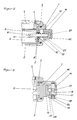
- the watch shown in the figures has a watch case, which has a cover ring 3 comprising a housing ring 1, a component 2 which can be screwed thereon and whose opening 2 closes and an also screwable thereon and which closes the other opening of the housing ring 1.
- the viewing opening of the watch which is covered by a watch glass 4, is also formed in the cover part 3.
- Radially directed recesses 6 are formed in the housing ring 1, which lead outwards from the housing interior 5 and in which a lead-through ring 7 is fixedly arranged.
- the feed-through ring 7 has on its inner lateral surface a radially circumferential annular groove 8, into which a sealing ring 3 is inserted.
- the sealing ring 9 encloses an axially displaceable actuating plunger 10 which is guided through the recess 6 from the outside to the interior of the housing and by means of which elements (not shown) arranged in the interior of the housing 5 can be controlled.
- the groove wall 12 removed from the housing interior 5 encloses the actuating plunger 10 at a greater distance.
- the actuating plunger 10 is guided in the region of the groove wall 11, but can pivot to a certain extent around the plane determined by the groove wall 11 and thus cannot jam.
- the actuating plunger 10 projects into the area of one end of a recess 13 of approximately rectangular cross-section formed in the housing ring 1 and open to the outside, and its outer free end lies on a key head 14 arranged in the recess 13, approximately the same cross-section as the recess 13 on.
- the key head 14 is pivotable about a pivot axis 15, which is arranged in the contact region of the actuating plunger 10 opposite end region of the key head 14 and extends approximately at right angles to the extent of the actuating plunger 10.
- the pivot axis 16 is formed by an axle bolt 16 which extends through an axle bore 17 in the key head 14 and is supported with its two ends protruding from the axle bore 17 in corresponding recesses 18 in the housing ring 1.
- the outwardly projecting end of the actuating plunger 10 is designed as a mushroom-shaped curved end 20 and protrudes into the basic bore 21 of the key head 14, which has approximately the same diameter as the mushroom-shaped end 20 of the actuating plunger 10.
- the base 22 of the base bore 21, which has just been formed and forms the contact surface for the actuating plunger 10, is approximately perpendicular to the longitudinal axis of the actuating plunger with half of its possible pivoting path pivoted into the recess 13.
- a further recess 23 which is open towards the housing ring 1, is formed in the key head 14, into which a radially projecting hook-shaped stop 24 protrudes fixedly arranged on the housing ring 1.
- the hook opening 25 is directed toward the pivot axis 15, the side surface of the hook opening 25 which is farther away from the housing ring being inclined ramp-like to the opening opening away from the housing ring 1 and forming a stop surface 26.
- a threaded bore 27 is formed in the key head 14, which starts from the end of the key head 14 on the pivot axis side and opens into the recess 23 with its other end. With the threaded bore 27 and the axial bore 17 intersect their peripheral regions.
- the threaded bolt 28 provided with an adjusting slot 30 at its end opposite the recess 23 can be rotated with a screwdriver. In the set rest position, the threaded bolt can be secured against automatic rotation by a locking adhesive.
- a central threaded bore 32 can be formed, into which a removal tool can be screwed. This is possible because the recess 18, which is further away from the observer, is a continuous recess.
Landscapes
- Physics & Mathematics (AREA)
- General Physics & Mathematics (AREA)
- Electric Clocks (AREA)
Applications Claiming Priority (2)
| Application Number | Priority Date | Filing Date | Title |
|---|---|---|---|
| DE4005243A DE4005243A1 (de) | 1990-02-20 | 1990-02-20 | Drucktastenanordnung |
| DE4005243 | 1990-02-20 |
Publications (2)
| Publication Number | Publication Date |
|---|---|
| EP0443087A1 true EP0443087A1 (fr) | 1991-08-28 |
| EP0443087B1 EP0443087B1 (fr) | 1993-12-08 |
Family
ID=6400532
Family Applications (1)
| Application Number | Title | Priority Date | Filing Date |
|---|---|---|---|
| EP90117638A Expired - Lifetime EP0443087B1 (fr) | 1990-02-20 | 1990-09-13 | Bouton poussoir |
Country Status (2)
| Country | Link |
|---|---|
| EP (1) | EP0443087B1 (fr) |
| DE (2) | DE4005243A1 (fr) |
Cited By (6)
| Publication number | Priority date | Publication date | Assignee | Title |
|---|---|---|---|---|
| EP0985984A1 (fr) * | 1998-09-10 | 2000-03-15 | Grandjean Sàrl | Dispositif d'actionnement d'un mécanisme pour boíte de montre de forme non circulaire |
| WO2001088633A1 (fr) * | 2000-05-18 | 2001-11-22 | The British Masters Sa | Dispositif de commande a poussoir pour montre |
| EP1818734A1 (fr) * | 2006-02-08 | 2007-08-15 | Montres Journe S.A. | Dispositif à poussoir pour commander une fonction de l'extérieur d'une boîte de montre |
| CH704691A1 (fr) * | 2011-03-24 | 2012-09-28 | Hublot Sa Geneve | Bouton-poussoir à guidage amélioré. |
| WO2013033666A1 (fr) * | 2011-09-01 | 2013-03-07 | Stefan Johansson | Boîtier de montre à poussoir et couronne intégrés |
| CN111983910A (zh) * | 2019-05-23 | 2020-11-24 | Meco有限公司 | 按钮系统和包括该按钮系统的钟表 |
Citations (4)
| Publication number | Priority date | Publication date | Assignee | Title |
|---|---|---|---|---|
| DE2207386A1 (de) * | 1971-02-19 | 1972-08-24 | Heuer Leonidas Sa | Sport- oder Chronometeruhr |
| GB2121992A (en) * | 1982-06-10 | 1984-01-04 | Timex Corp | Timepiece assembly with switch |
| DE3309321A1 (de) * | 1983-03-16 | 1984-09-27 | IWC International Watch Co AG, Schaffhausen | Drucktastenanordnung |
| DE3421882A1 (de) * | 1984-06-13 | 1985-12-19 | Tesch AG, Ennetbürgen | Uhrengehaeuse mit drucktasten |
Family Cites Families (1)
| Publication number | Priority date | Publication date | Assignee | Title |
|---|---|---|---|---|
| DE3239553C1 (de) * | 1982-10-26 | 1984-01-26 | Tesch AG, 6373 Ennetbürgen | Uhrengehaeuse mit Drucktasten |
-
1990
- 1990-02-20 DE DE4005243A patent/DE4005243A1/de not_active Ceased
- 1990-09-13 EP EP90117638A patent/EP0443087B1/fr not_active Expired - Lifetime
- 1990-09-13 DE DE90117638T patent/DE59003799D1/de not_active Expired - Fee Related
Patent Citations (4)
| Publication number | Priority date | Publication date | Assignee | Title |
|---|---|---|---|---|
| DE2207386A1 (de) * | 1971-02-19 | 1972-08-24 | Heuer Leonidas Sa | Sport- oder Chronometeruhr |
| GB2121992A (en) * | 1982-06-10 | 1984-01-04 | Timex Corp | Timepiece assembly with switch |
| DE3309321A1 (de) * | 1983-03-16 | 1984-09-27 | IWC International Watch Co AG, Schaffhausen | Drucktastenanordnung |
| DE3421882A1 (de) * | 1984-06-13 | 1985-12-19 | Tesch AG, Ennetbürgen | Uhrengehaeuse mit drucktasten |
Cited By (13)
| Publication number | Priority date | Publication date | Assignee | Title |
|---|---|---|---|---|
| EP0985984A1 (fr) * | 1998-09-10 | 2000-03-15 | Grandjean Sàrl | Dispositif d'actionnement d'un mécanisme pour boíte de montre de forme non circulaire |
| US6247841B1 (en) | 1998-09-10 | 2001-06-19 | Grandjean Sarl | Device for actuating a mechanism for a watch case of non circular shape |
| WO2001088633A1 (fr) * | 2000-05-18 | 2001-11-22 | The British Masters Sa | Dispositif de commande a poussoir pour montre |
| US7001064B2 (en) | 2000-05-18 | 2006-02-21 | Finazzi Pierre-Andre | Push-piece control device for a watch |
| EP1818734A1 (fr) * | 2006-02-08 | 2007-08-15 | Montres Journe S.A. | Dispositif à poussoir pour commander une fonction de l'extérieur d'une boîte de montre |
| WO2007090307A3 (fr) * | 2006-02-08 | 2007-10-25 | Montres Journe S A | Dispositif a poussoir pour commander les fonctions marche/arret et remise a zero d'un mecanisme de chronographe |
| US7570545B2 (en) | 2006-02-08 | 2009-08-04 | Montres Journe S.A. | Pushbutton device for controlling the start/stop and resetting functions of a chronograph mechanism |
| CH704691A1 (fr) * | 2011-03-24 | 2012-09-28 | Hublot Sa Geneve | Bouton-poussoir à guidage amélioré. |
| WO2013033666A1 (fr) * | 2011-09-01 | 2013-03-07 | Stefan Johansson | Boîtier de montre à poussoir et couronne intégrés |
| CN111983910A (zh) * | 2019-05-23 | 2020-11-24 | Meco有限公司 | 按钮系统和包括该按钮系统的钟表 |
| EP3742235A1 (fr) * | 2019-05-23 | 2020-11-25 | Meco S.A. | Systeme de bouton-poussoir, et piece d'horlogerie le comprenant |
| CN111983910B (zh) * | 2019-05-23 | 2022-06-21 | Meco有限公司 | 按钮系统和包括该按钮系统的钟表 |
| US11886150B2 (en) | 2019-05-23 | 2024-01-30 | Meco Sa | Push button system and timepiece comprising the same |
Also Published As
| Publication number | Publication date |
|---|---|
| DE4005243A1 (de) | 1991-08-22 |
| EP0443087B1 (fr) | 1993-12-08 |
| DE59003799D1 (de) | 1994-01-20 |
Similar Documents
| Publication | Publication Date | Title |
|---|---|---|
| DE4219956C2 (de) | Schneideinrichtung für eine Motorkettensäge | |
| DE1927901A1 (de) | Drehknopf | |
| CH700807B1 (de) | Zeitmesser. | |
| DE3843095C2 (de) | Befestigungseinrichtung für Verkleidungen | |
| EP0623942A1 (fr) | Codeur | |
| EP0749629B1 (fr) | Interrupteur de securite | |
| EP0443087B1 (fr) | Bouton poussoir | |
| EP0604898A1 (fr) | Interrupteur pour la commande d'un appareil électrotechnique, en particulier un appareil de télécommande | |
| EP0235350B1 (fr) | Interrupteur, en particulier pour véhicule | |
| EP0235349A2 (fr) | Serrure pour levier de frein à main de véhicules à moteur | |
| EP0754827B1 (fr) | Dispositif pour la fixation amovible et axialement non coulissante d'une poignée sur un élément de palier, notamment pour une poignée de porte ou fenêtre | |
| DE4200096A1 (de) | Vorrichtung zum verschliessen einer oeffnung in einer verkleidung | |
| EP0187314A2 (fr) | Tête de distribution pour pulvérisateur | |
| DE4201570A1 (de) | Stellvorrichtung | |
| EP0215295B1 (fr) | Accouplement pour l'assemblage détachable d'un manche de pièce à main dentaire avec une tête | |
| DE2536501A1 (de) | Verrastbare schaltvorrichtung fuer digitaluhren | |
| EP1552199A1 (fr) | Robinet de gaz comportant une soupape de securite electromagnetique et insert magnetique destine a une soupape de securite electromagnetique | |
| EP0152782B1 (fr) | Pince | |
| DE20309658U1 (de) | Tür- oder Fensterbeschlag | |
| DE3519368A1 (de) | Drehschalter | |
| EP0400207A1 (fr) | Bouton-poussoir | |
| EP0569931A1 (fr) | Poignée | |
| DE9113754U1 (de) | Elektrischer Kurzhub-Drucktaster | |
| DE69319694T2 (de) | Ein Instrument mit einem entfernbaren Deckel | |
| DE3942924C2 (de) | Obenliegender Türschließer mit einer schließergehäuseübergreifenden Kappe |
Legal Events
| Date | Code | Title | Description |
|---|---|---|---|
| PUAI | Public reference made under article 153(3) epc to a published international application that has entered the european phase |
Free format text: ORIGINAL CODE: 0009012 |
|
| 17P | Request for examination filed |
Effective date: 19910427 |
|
| AK | Designated contracting states |
Kind code of ref document: A1 Designated state(s): CH DE FR IT LI |
|
| 17Q | First examination report despatched |
Effective date: 19920710 |
|
| GRAA | (expected) grant |
Free format text: ORIGINAL CODE: 0009210 |
|
| AK | Designated contracting states |
Kind code of ref document: B1 Designated state(s): CH DE FR IT LI |
|
| PG25 | Lapsed in a contracting state [announced via postgrant information from national office to epo] |
Ref country code: IT Free format text: LAPSE BECAUSE OF FAILURE TO SUBMIT A TRANSLATION OF THE DESCRIPTION OR TO PAY THE FEE WITHIN THE PRESCRIBED TIME-LIMIT;WARNING: LAPSES OF ITALIAN PATENTS WITH EFFECTIVE DATE BEFORE 2007 MAY HAVE OCCURRED AT ANY TIME BEFORE 2007. THE CORRECT EFFECTIVE DATE MAY BE DIFFERENT FROM THE ONE RECORDED. Effective date: 19931208 |
|
| ET | Fr: translation filed | ||
| REF | Corresponds to: |
Ref document number: 59003799 Country of ref document: DE Date of ref document: 19940120 |
|
| PLBE | No opposition filed within time limit |
Free format text: ORIGINAL CODE: 0009261 |
|
| STAA | Information on the status of an ep patent application or granted ep patent |
Free format text: STATUS: NO OPPOSITION FILED WITHIN TIME LIMIT |
|
| 26N | No opposition filed | ||
| PG25 | Lapsed in a contracting state [announced via postgrant information from national office to epo] |
Ref country code: FR Effective date: 19950531 |
|
| PG25 | Lapsed in a contracting state [announced via postgrant information from national office to epo] |
Ref country code: DE Effective date: 19950601 |
|
| REG | Reference to a national code |
Ref country code: FR Ref legal event code: ST |
|
| PGFP | Annual fee paid to national office [announced via postgrant information from national office to epo] |
Ref country code: CH Payment date: 19990816 Year of fee payment: 10 |
|
| PG25 | Lapsed in a contracting state [announced via postgrant information from national office to epo] |
Ref country code: LI Free format text: LAPSE BECAUSE OF NON-PAYMENT OF DUE FEES Effective date: 20000930 Ref country code: CH Free format text: LAPSE BECAUSE OF NON-PAYMENT OF DUE FEES Effective date: 20000930 |
|
| REG | Reference to a national code |
Ref country code: CH Ref legal event code: PL |