EP0443101A2 - Means for easy deboning of carcass parts, in particular of bovine quarters - Google Patents
Means for easy deboning of carcass parts, in particular of bovine quarters Download PDFInfo
- Publication number
- EP0443101A2 EP0443101A2 EP90121726A EP90121726A EP0443101A2 EP 0443101 A2 EP0443101 A2 EP 0443101A2 EP 90121726 A EP90121726 A EP 90121726A EP 90121726 A EP90121726 A EP 90121726A EP 0443101 A2 EP0443101 A2 EP 0443101A2
- Authority
- EP
- European Patent Office
- Prior art keywords
- transport
- plant according
- track section
- section
- transport path
- Prior art date
- Legal status (The legal status is an assumption and is not a legal conclusion. Google has not performed a legal analysis and makes no representation as to the accuracy of the status listed.)
- Withdrawn
Links
Images


Classifications
-
- A—HUMAN NECESSITIES
- A22—BUTCHERING; MEAT TREATMENT; PROCESSING POULTRY OR FISH
- A22B—SLAUGHTERING
- A22B5/00—Accessories for use during or after slaughtering
- A22B5/0017—Apparatus for cutting, dividing or deboning carcasses
- A22B5/0029—Cutting through or detaching portions of a carcass
-
- A—HUMAN NECESSITIES
- A22—BUTCHERING; MEAT TREATMENT; PROCESSING POULTRY OR FISH
- A22B—SLAUGHTERING
- A22B7/00—Slaughterhouse arrangements
- A22B7/001—Conveying arrangements
Definitions
- a relatively short, first transport track section is arranged such that its front end can be lowered in the transport direction.
- a stop is provided at the front end of this pivotable transport track section.
- the propulsion unit extends at a distance parallel to the second transport track section adjoining to the front in the transport direction.
- a first region of a slaughter animal part to be dismantled which is attached to a transport hook on the first transport track section and is fixed by the stop, is thereby held in the back while a second region of the slaughter animal part to be dismantled, which is suspended by a transport hook on the second transport track section, is moved forward by means of the engaging part of the propulsion unit.
- the working disassembler can perform his trigger cuts or disassembly cuts with ease; Due to the pulling action of the device, its cutting area is opened or kept open. The cutting takes place hygienically when the parts of the slaughter animal are hanging.
- the lowerability of the first transport track section has the purpose of being able to lower the first area of the slaughter animal part to such an extent that the two areas of the slaughter animal part can be pulled apart with the device without substantial "misalignment" of the slaughter animal part.
- the working conditions of the cutters working on the known device are not optimal, because the hanging length of the parts of the slaughtered animal varies depending on the size of the slaughtered animal (even if, for example, it is always cattle), because the fore quarters, long hind quarters and short hind quarters of the slaughter animals change are to be disassembled, and because the disassembler has to make his cuts further up and down on the animal part to be disassembled.
- the invention has for its object to make available a system of the type mentioned, which enables the disassembler to work in an ergonomic, optimal height position. This is particularly important because the dismantling of parts of slaughter animals is a physically very strenuous activity and a disassembler performs the better, depending on the beque mer and less tired he can work.
- the entire slaughter animal part can thus be raised or lowered in an optimal height position for the work of the cutting unit, regardless of the length of the respective slaughter animal part. It is possible for the decomposer, for example after having carried out part of his cutting work, to lift the slaughter animal part so that he can again work in a comfortable height position for the rest of his cutting work.
- the device is in principle also suitable for facilitating the dismantling of entire carcasses.
- the main field of application is the dismantling of parts of slaughter animals, in particular fore quarters, long hind quarters (with a piece of spine and a few ribs) and short hind quarters quarters of cattle.
- the system 50 is preferably designed such that the transport path section can be moved both upwards and downwards in comparison to a neutral height position, in which it passes into the subsequent transport path essentially without a change in height.
- the transport track section can only be moved downwards or upwards from this neutral height position.
- the movability is preferably provided in a substantially vertical direction.
- the term "motor" of the propulsion unit is to be understood comprehensively; in principle, it can be implemented by any suitable drive device. Hydraulic or pneumatic cylinder-piston units are mentioned as examples. However, an electric motor is particularly preferred, particularly because of its good controllability.
- the adjustability of the cut-off propulsive force threshold of the propelling unit primarily serves to be able to adjust the propulsive force to the particular meat texture (soft or firm).
- the disassembler 's work is such that, during the Driving force prevails, cuts. If with increasing "spreading" of the first area and the second area of the slaughter animal part, the driving force continues to increase, a state can be repeatedly reached in which the driving unit switches itself off until the cutter has made further cuts and, as a result, continues to spread reduced propulsive force is possible.
- the speed of movement of the engaging part of the propulsion unit is preferably also adjustable.
- Strain gauges and electrical load cells are preferred as sensors of the propulsion unit. Electric load cells are even more special because they are more precise and robust.
- the guidance is preferably carried out with rolling elements on essentially vertical supports.
- Hydraulic and pneumatic cylinder-piston units are suitable for moving the frame and for moving the height of the first transport track section (cf. claims 10 to 12), with pneumatic cylinder-piston units generally being preferred.
- the dismantling plant which is best manageable in the plan view in FIG. 1, has a first device 2 ("pre-cutting station"), a second device 4 ("pre-dismantling station") and two third devices 6 (“dismantling stations” connected in series) - progressing in the cattle quarter transport direction ”) on.
- a transport path 8 runs through these four devices 2, 4, 6 and is connected at the beginning of the first device 2 'to a leading transport path 10 of the slaughterhouse and behind the fourth device 6 to a leading transport path 12 of the slaughterhouse.
- a relatively short transport path section 14 (referred to in claim 14 as “third transport path section") is connected to the transport path 8 by means of a front and a rear, telescopically variable length, hingedly connected transport path intermediate piece 16.
- the vertical piston rod 18 of a cylinder-piston unit 19 is fastened to the transport track section 14.
- the lower end of the cylinder of the cylinder-piston unit 19 is fastened to a transverse yoke 20 and the upper end of this cylinder is free.
- Two parallel, hydraulic cylinder-piston units 24 act between the transverse yoke 20 and a longitudinal support 22 extending above it.
- the transport path section 14 can be lifted up out of the plane of the transport path 8 by means of the Cylinder-piston units 24, the conveyor track section 14 can be lowered from the plane of the conveyor track 8 downwards, both as indicated by dashed lines in FIG. 5.
- the conveyor track section 14 maintains its orientation parallel to the plane of the conveyor track 8. If a transport hook 26 (cf. FIG. 2), on which a quarter of a cow hangs, is pushed onto the transport track section 14, the quarter of the cow can be raised or lowered by the described height travel, depending on the needs of the disassembler working at this station.
- the second device 4 which can be seen particularly clearly in FIG. 5, on the left, is constructed quite analogously to the first device 2 described.
- an inclined partition 28 is only below the transport path 8 provided, on which the quarter of the beef to be processed is supported on the side facing away from the cutter.
- the inclined cutting wall 28 can be pivoted from a vertical position, in which it is located on the side and allows cattle quarters to be pushed past, and a slightly upwardly tilted position, in which it supports a cattle quarter to be processed, by means of a pneumatic cylinder-piston unit.
- the third device 6 and the fourth device 6 are constructed almost identically, so that they are described only once.
- the device 6 mainly consists of a frame 30 which is essentially rectangular in plan view, four vertical guide beams 32 in the corner regions of the frame 30, and a propulsion unit 34 which is fastened to the frame 30 and extends parallel to a transport track section 36 of the third device 6.
- the frame 30 is essentially in a horizontal plane.
- the frame 30 essentially consists of two side members 38 and four cross members 40 connecting the side members 38.
- the transport track section 36 is fastened to the underside of the frame 30 centrally between the two longitudinal beams 38.
- the cross members 40 are extended beyond the longitudinal members 38 there.
- the propulsion unit 34 is fastened there under the cross members 40 of the frame 30, left or right next to and parallel to the transport track section 36.
- Each guide beam 32 consists of a pair of U-beams which are juxtaposed with their open sides, leaving a gap. At the two ends of both the foremost and the rearmost cross member 40, rollers 42 are attached which engage in the interior of the pair of guide supports 32 in question.
- the guide beams 32 can also be made from a round, square or rectangular tube or another profile.
- the hollow profiles are provided with a slot on one side.
- sliding shoes or sliding sleeves made of metal or plastic can also be used. When using rollers, slide shoes or sliding sleeves arranged on the outside on the guide supports 32, no slots or gaps are required in the guide supports 32.
- a vertical, pneumatic cylinder-piston unit 44 is attached to both the front and rear ends of each longitudinal member 38. Each cylinder-piston unit 44 is fastened at the top to a solid cross member 46 of the device frame.
- the frame 30 can be moved in the vertical direction by means of the cylinder-piston units 44, it being guided through the rollers 42, sliding blocks or sliding sleeves along the guide carrier 32. With the frame 30, the transport track section 36 and the propulsion unit 34 move up and down in translation. The frame 30 can be moved up and down relative to a neutral height position in which the transport track section 36 is aligned with the subsequent transport track 8.
- the propulsion unit 34 mainly has an electric drive geared motor 50 with a straight, elongated housing 48 which is longitudinally slotted on one side, a threaded spindle which is rotatably arranged therein and is not visible in FIG. 3 rotating driving of the threaded spindle, a carriage 52 which can be moved along the housing 48, and an arm 54 which projects transversely to the longitudinal extent of the housing 48 from the carriage 52 as an engagement device on a quarter of a cow to be dismantled.
- One or more traveling nuts sit on the threaded spindle and are connected to the carriage 52, so that the latter is moved in the longitudinal direction when the threaded spindle rotates.
- the arm 54 not shown in FIG. 2, is located somewhat below the pipe section 36.
- a force sensor in particular in the form of a strain gauge or an electrical weighing cell, is arranged on the suspension 56 (FIG. 2) of the propulsion unit 34, so that there is continuously detected how great a longitudinal force the propulsion unit 34 has on the arms 54 that are gripped by the arm 54. exercises the first area of the beef quarter to be dismantled.
- the electric motor 50 is switched off via a circuit (not shown) when this longitudinal force exceeds an adjustable threshold value. When the longitudinal force falls below the set threshold value again, the electric motor 50 is switched on again.
- the third devices 6 are mounted on supports 58 which rest on the slaughterhouse floor. It is alternative possible to design the devices 6 as hanging on the slaughterhouse ceiling or the slaughterhouse walls.
- FIG. 4 shows one of the dismantling stations 6, the jacking unit 34 lying in front of the plane of the drawing not being visible.
- frame 30, cylinder-piston units 44 and transport path section 36 FIG. 4 shows that the transport path section 36 in the transport direction at the front, that is to the left in FIG. 4, via a telescopically variable length, at both ends articulated transport path intermediate piece 60 is connected to the further transport path.
- a rocker 62 is arranged between the rear end of the transport path section 36 and the approaching transport path 8, which is the right end in FIG.
- the frame 30 and thus the transport path section 36 can be raised or lowered relative to the neutral position drawn with a solid line, in which case the transport path intermediate piece 60 and the rocker arm 62 assume oblique positions. Regardless of this height mobility, the rocker 62 can be lowered relative to the conveyor track section 36.
- the height mobility of the rocker 62 shown in FIG. 4 is only one of several possibilities for making the first transport track section movable in height.
- a translatory height mobility of the first transport track section could be provided.
- a further possibility is not to assign the rocker 62 or a first transport track section that is translationally height-adjustable to the frame 30 (whereby it moves up and down together with the frame 30), but rather the rocker 62 or a first transport track section that is translationally height-adjustable a suitable stationary battle hanging up the courtyard.
- the rocker 2 or the translationally vertically movable first transport path section would in principle guide its height movement independently of the height movement of the second transport path section.
- the spinous processes and ribs are then separated at the pre-cutting station 4, for example with the aid of a saw that can be adjusted in depth and is operated by compressed air.
- the lock bone is then released from a piece of meat called "upper shell” at the first dismantling station 6 and a hook is hung in the hole in the lock bone. This hook is pushed onto the rocker 62.
- the propulsion unit 34 is switched on, and its engaging part 54 engages at the top of the leg of the hind quarter, so that leg meat with tubular bones is pulled away from the held lock bone.
- the splitter cuts along the lock bone.
- the lock bone with attached vertebral body hangs on the rocker 62, while the leg meat with tubular bones and roast beef and ribs is separately attached to it the trans hang portbahn section 36.
- the lock bone with adhering vertebral body is discharged at a transport track switch 70 (FIG. 1) and processed further at a bone processing station which is not drawn and described in detail.
- the part of the rear quarter hanging on the second hook is pushed to the second dismantling station 6.
- There a hook is hooked into the leg meat and this is hung on the rocker 62 there.
- the connected tubular bones are pulled forward with the propulsion unit 34 there, while the hook hanging on the rocker 62 is retained.
- the cutter cuts along the long bones.
- the remaining bone components of the rear quarter are caught on the height-adjustable transport track section 36, while the entire meat components of the rear quarter are caught on the hook that hangs on the rocker 62.
- a further variant consists in placing the pre-dismantling station 4 between the two described dismantling stations 6.
- a typical range of the height of the neutral position of the second transport track section 36 is 2.3 to 2.7 m.
- a typical range of the height travel of the second transport track section 36 is 10 to 50 cm either only in one direction from the neutral position or by this amount both up and down from the neutral position.
Landscapes
- Life Sciences & Earth Sciences (AREA)
- Engineering & Computer Science (AREA)
- Food Science & Technology (AREA)
- Processing Of Meat And Fish (AREA)
Abstract
Description
Die Erfindung bezieht sich auf eine Anlage zum erleichterten Zerlegen von Schlachttier-Teilen, insbesondere Rindervierteln, mit:
- (a) einem höhenbeweglichen, ersten Transportbahnabschnitt zum Abstützen von Transporthaken für angehängte Schlachttier-Teile;
- (b) einer dem ersten Transportbahnabschnitt zugeordneten, aktivierbaren und passivierbaren Transporthaken-Blockiereinrichtung zum Bewegungsblockieren von Transporthaken auf dem ersten Transportbahnabschnitt.
- (c) einem zweiten Transportbahnabschnitt zum Abstützen von Transporthaken für angehängte Schlachttier-Teile; und
- (d) einer Vortriebseinheit, die einen Motor und mittels des Motors bewegbares Angreifteil zum Angreifen an einem zweiten Bereich des jeweiligen, zu zerlegenden Schlachttier-Teils aufweist, so daß der an einem Transporthaken des zweiten Transportbahnabschnitts hängende, zweite Bereich des Schlachttier-Teils und ein an einem Transporthaken des ersten Transportbahnabschnitts hängender, durch die Blockiereinrichtung festgelegter, erster Bereich des Schlachttier-Teils kraftbetätigt auseinander bewegbar sind.
- (a) a vertically movable, first transport track section for supporting transport hooks for attached slaughter animal parts;
- (b) an activatable and passivable transport hook blocking device assigned to the first transport path section for blocking movement of transport hooks on the first transport path section.
- (c) a second transport track section for supporting transport hooks for attached slaughter animal parts; and
- (d) a propulsion unit which has a motor and an engaging part movable by means of the motor for engaging a second area of the respective slaughter animal part to be dismantled, so that the second area of the slaughter animal part hanging on a transport hook of the second transport track section and a hanging on a transport hook of the first transport track section and fixed by the blocking device, the first region of the slaughter animal part can be moved apart in a force-actuated manner.
Anlagen dieser Art sind käuflich erhältlich. Bei diesen Anlagen ist ein relativ kurzer, erster Transportbahnabschnitt derart schwenkbar angeordnet, daß sich sein in Transportrichtung vorderes Ende absenken läßt. Am vorderen Ende dieses schwenkbaren Transportbahnabschnitts ist ein Anschlag vorgesehen. Die Vortriebseinheit erstreckt sich beabstandet parallel zu dem in Transportrichtung nach vorn anschließenden, zweiten Transportbahnabschnitt. Ein an einem Transporthaken am ersten Transportbahnabschnitt hängender, durch den Anschlag festgelegter, erster Bereich eines zu zerlegenden Schlachttier-Teils wird dadurch hinten gehalten, während ein durch einen Transporthaken am zweiten Transporbahnabschnitt hängender, zweiter Bereich des zu zerlegenden Schlachttierteils mittels des Angreifteils der Vortriebseinheit nach vorn bewegt wird. Infolgedessen kann der arbeitende Zerleger seine Auslöseschnitte oder Zerlegeschnitte erleichtert führen; durch die Auseinanderziehwirkung der Vorrichtung wird ihm sein Schneidbereich geöffnet bzw. offen gehalten. Die Zerlegung erfolgt hygienisch im hängenden Zustand der Schlachttier-Teile. Die Absenkbarkeit des ersten Transportbahnabschnitts hat den Sinn, den ersten Bereich des Schlachttier-Teils so weit absenken zu können, daß die beiden Bereiche des Schlachttier-Teils ohne wesentliche "Schiefstellung" des Schlachttierteils mit der Vorrichtung auseinandergezogen werden können.Systems of this type are commercially available. In these systems, a relatively short, first transport track section is arranged such that its front end can be lowered in the transport direction. A stop is provided at the front end of this pivotable transport track section. The propulsion unit extends at a distance parallel to the second transport track section adjoining to the front in the transport direction. A first region of a slaughter animal part to be dismantled, which is attached to a transport hook on the first transport track section and is fixed by the stop, is thereby held in the back while a second region of the slaughter animal part to be dismantled, which is suspended by a transport hook on the second transport track section, is moved forward by means of the engaging part of the propulsion unit. As a result, the working disassembler can perform his trigger cuts or disassembly cuts with ease; Due to the pulling action of the device, its cutting area is opened or kept open. The cutting takes place hygienically when the parts of the slaughter animal are hanging. The lowerability of the first transport track section has the purpose of being able to lower the first area of the slaughter animal part to such an extent that the two areas of the slaughter animal part can be pulled apart with the device without substantial "misalignment" of the slaughter animal part.
Die Arbeitsbedingungen der an der bekannten Vorrichtung arbeitenden Zerleger sind nicht optimal, weil die Hängelänge der Schlachttier-Teile je nach Größe des geschlachteten Tiers (auch wenn es sich beispielsweise immer um Rinder handelt) variiert, weil wechselnd Vorderviertel, lange Hinterviertel und kurze Hinterviertel der Schlachttiere zu zerlegen sind, und weil der Zerleger seine Schnitte weiter oben und weiter unten an dem zu zerlegenden Schlachttier-Teil führen muß.The working conditions of the cutters working on the known device are not optimal, because the hanging length of the parts of the slaughtered animal varies depending on the size of the slaughtered animal (even if, for example, it is always cattle), because the fore quarters, long hind quarters and short hind quarters of the slaughter animals change are to be disassembled, and because the disassembler has to make his cuts further up and down on the animal part to be disassembled.
Der Erfindung liegt die Aufgabe zugrunde, eine Anlage der eingangs genannten Art verfügbar zu machen, die dem Zerleger ein Arbeiten in ergonomischer, optimaler Höhenposition ermöglicht. Dies hat deshalb besondere Bedeutung, weil das Zerlegen von Schlachttier-Teilen eine körperlich sehr anstrengende Tätigkeit ist und ein Zerleger eine um so höhere Leistung erbringt, je beque mer und ermüdungsfreier er arbeiten kann.The invention has for its object to make available a system of the type mentioned, which enables the disassembler to work in an ergonomic, optimal height position. This is particularly important because the dismantling of parts of slaughter animals is a physically very strenuous activity and a disassembler performs the better, depending on the beque mer and less tired he can work.
Zur Lösung dieser Aufgabe ist die Zerlegeerleichterungsanlage dadurch gekennzeichnet,
- (e) daß der zweite Transportbahnabschnitt und die Vortriebseinheit an einem Rahmen befestigt sind;
- (f) daß der Rahmen längs einer Führung mechanisiert in unterschiedliche Höhenpositionen verfahrbar ist; und
- (g) daß der erste Transportbahnabschnitt so weit höhenbeweglich ist, daß seine Bewegungsblockierstelle auf eine niedrigere Höhe als die gewählte Höhenposition des zweiten Transportbahnabschnitts bringbar ist.
- (e) that the second conveyor track section and the propulsion unit are attached to a frame;
- (f) that the frame can be mechanically moved along a guide to different height positions; and
- (g) that the first transport path section is sufficiently movable in height that its movement blocking point can be brought to a lower height than the selected height position of the second transport path section.
Bei der erfindungsgemäsen Anlage läßt sich somit, unabhängig von der Länge des jeweiligen Schlachttier-Teils, das gesamte Schlachttier-Teil anheben oder absenken in optimaler Höhenposition für die Arbeit des Zerlegers. Es ist dem Zerleger möglich, beispielsweise nach einem Teil der Durchführung seiner Zerlegearbeit, das Schlachttier-Teil anzuheben, damit er für den Rest seiner Zerlegarbeit wiederum in bequemer Höhenposition arbeiten kann.In the system according to the invention, the entire slaughter animal part can thus be raised or lowered in an optimal height position for the work of the cutting unit, regardless of the length of the respective slaughter animal part. It is possible for the decomposer, for example after having carried out part of his cutting work, to lift the slaughter animal part so that he can again work in a comfortable height position for the rest of his cutting work.
Es wird darauf hingewiesen, das die Vorrichtung prinzipiell auch dafür geeignet ist, die Zerlegung gesamter Schlachttierkörper zu erleichtern. Haupteinsatzfeld ist jedoch die Zerlegung von Schlachttier-Teilen, insbesondere Vordervierteln, langen Hintervierteln (mit einem Stück WirbeLsäule und einigen Rippen) und kurzen Hinter vierteln von Rindern.It is pointed out that the device is in principle also suitable for facilitating the dismantling of entire carcasses. The main field of application, however, is the dismantling of parts of slaughter animals, in particular fore quarters, long hind quarters (with a piece of spine and a few ribs) and short hind quarters quarters of cattle.
Vorzugsweise ist die Anlage 50 ausgebildet, daß der Transportbahnabschnitt im Vergleich zu einer Neutral-Höhenposition, in der er im wesentlichen ohne Höhenänderung in die anschließende Transportbahn übergeht, sowohl nach oben als auch nach unten verfahrbar ist. Es ist jedoch alternativ möglich, die Anlage so auszulegen, das der Transportbahnabschnitt aus dieser Neutral-Höhenposition nur nach unten oder oben verfahrbar ist.The
Die Verfahrbarkeit ist vorzugsweise in im wesentlichen senkrechter Richtung vorgesehen.The movability is preferably provided in a substantially vertical direction.
Der Begriff "Motor" der Vortriebseinheit ist umfassend zu verstehen; er kann im Prinzip durch jede geeignete Antriebseinrichtung verwirklicht sein. Als Beispiele seien hydraulische oder pneumatische Zylinder-Kolben-Einheiten genannt. Besonders bevorzugt ist jedoch, insbesondere wegen seiner guten Regelbarkeit, ein Elektromotor.The term "motor" of the propulsion unit is to be understood comprehensively; in principle, it can be implemented by any suitable drive device. Hydraulic or pneumatic cylinder-piston units are mentioned as examples. However, an electric motor is particularly preferred, particularly because of its good controllability.
Bevorzugte Ausgestaltungen der Erfindung ergeben sich aus den Unteransprüchen. Zu den Unteranspruchsmerkmalen werden gleich anschließend oder im Zusammenhang mit dem Beispiel steil der Beschreibung noch weitere Ausführungen gemacht.Preferred embodiments of the invention result from the subclaims. Further explanations are made immediately afterwards or in connection with the example steeply in the description of the subclaim features.
Die Einstellbarkeit der Abschalt-Vortriebskraftschwelle der Vortriebseinheit dient in erster Linie dazu, die Vortriebskraft auf die jeweilige Fleischbeschaffenheit (weich oder fest) einstellen zu können. In der Praxis läuft die Arbeit des Zerlegers so ab, daß er, während die Vortriebskraft herrscht, schneidet. Wenn mit zunehmender "Spreizung" des ersten Bereichs und des zweiten Bereichs des Schlachttier-Teils die vortriebskraft immer weiter ansteigt, kann wiederholt ein Zustand erreicht werden, bei dem sich die Vortriebseinheit selbsttätig abschaltet, bis der Zerleger weitere Schnitte geführt hat und infolgedessen ein Weiterspreizen mit erniedrigter vortriebskraft möglich ist. Vorzugsweise ist auch die Bewegungsgeschwindigkeit des Angreifteils der Vortriebseinheit einstellbar.The adjustability of the cut-off propulsive force threshold of the propelling unit primarily serves to be able to adjust the propulsive force to the particular meat texture (soft or firm). In practice, the disassembler 's work is such that, during the Driving force prevails, cuts. If with increasing "spreading" of the first area and the second area of the slaughter animal part, the driving force continues to increase, a state can be repeatedly reached in which the driving unit switches itself off until the cutter has made further cuts and, as a result, continues to spread reduced propulsive force is possible. The speed of movement of the engaging part of the propulsion unit is preferably also adjustable.
Als Sensoren der Vortriebseinheit sind Dehnungsmeßstreifen und elektrische Wiegezellen bevorzugt. Elektrische Wiegezellen sogar ganz besonders, weil sie genauer und robuster sind.Strain gauges and electrical load cells are preferred as sensors of the propulsion unit. Electric load cells are even more special because they are more precise and robust.
Die Führung erfolgt vorzugsweise mit Rollkörpern an im wesentlichen vertikalen Trägern.The guidance is preferably carried out with rolling elements on essentially vertical supports.
Zum verfahren des Rahmens und zum Höhenbewegen des ersten Transportbahnabschnitts (vgl. Ansprüche 10 bis 12) eignen sich hydraulische und pneumatische Zylinder-Kolben-Einheiten, wobei pneumatische Zylinder-Kolben-Einheiten in der Regel bevorzugt sind.Hydraulic and pneumatic cylinder-piston units are suitable for moving the frame and for moving the height of the first transport track section (cf.
Statt mittels des Rahmens den zweiten Transportbahnabschnitt und die vortriebseinheit gemeinsam aufwärts und abwärts zu verfahren, ist es in ganz äquivalenter Weise möglich, gesonderte Höhenverfahrbarkeiten für den zweiten Transportbahnabschnitt für sich und die Vortriebseinheit für sich vorzusehen oder die Vortriebseinheit nicht höhenverfahrbar zu machen und statt dessen eine Höhenverfahrbarkeit des Angreifteils relativ zu der Vortriebs einheit vorzusehen.Instead of moving the second transport track section and the propulsion unit together upwards and downwards by means of the frame, it is possible in an entirely equivalent manner to provide separate height travel options for the second transport track section for themselves and the propulsion unit or to make the propulsion unit not height-adjustable and instead use one Height of the engaging part relative to the advance to provide unit.
Die Erfindung und Ausgestaltungen der Erfindung werden nachfolgend anhand eines zeichnerisch dargestellten, bevorzugten Ausführungsbeispiels noch näher erläutert. Es zeigt:
- Fig. 1 eine Draufsicht auf eine Rinderviertel-Zerlegeanlage;
- Fig. 2 eine Stirnansicht der Zerlegeanlage von Fig. 1 gemäß Pfeil II in Fig. 1;
- Fig. 3 eine Ausschnitts-Draufsicht der Anlage von Fig. 1;
- Fig. 4 eine Ausschnitts-Seitenansicht der Anlage von Fig. 1 gemäß Pfeilen IV-IV;
- Fig. 5 eine weitere Ausschnitts-Seitenansicht der Anlage von Fig. 1 gemäß Pfeilen V-V;
- Figure 1 is a plan view of a quarter beef cutting plant.
- FIG. 2 shows an end view of the dismantling plant from FIG. 1 according to arrow II in FIG. 1;
- Fig. 3 is a sectional top view of the system of Fig. 1;
- FIG. 4 shows a sectional side view of the system from FIG. 1 according to arrows IV-IV;
- FIG. 5 shows a further detail side view of the system from FIG. 1 according to arrows VV;
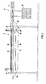
Die in der Draufsicht in der Fig. 1 am besten überschaubare Zerlegeanlage weist - in Rinderviertel-Transportrichtung fortschreitend - eine erste Vorrichtung 2 ("Vorschneidstation"), eine zweite Vorrichtung 4 ("Vorzerlegestation") sowie zwei hintereinandergeschaltete, dritte Vorrichtungen 6 ("Zerlegestationen") auf. Eine Transportbahn 8 zieht sich durch diese vier Vorrichtungen 2, 4, 6 und ist am Anfang der ersten Vorrichtung 2′ an eine heran führende Transportbahn 10 des Schlachthofs angeschlossen und hinter der vierten Vorrichtung 6 an eine weg führende Transportbahn 12 des Schlachthofs angeschlossen.The dismantling plant, which is best manageable in the plan view in FIG. 1, has a first device 2 ("pre-cutting station"), a second device 4 ("pre-dismantling station") and two third devices 6 ("dismantling stations" connected in series) - progressing in the cattle quarter transport direction ") on. A transport path 8 runs through these four
Den Aufbau der ersten Vorrichtung 2 erkennt man am besten in Fig. 5, rechts. Ein relativ kurzer Transportbahnabschnitt 14 (in Anspruch 14 "dritter Transportbahnabschnitt" genannt) ist mittels eines vorderen und eines hinteren, teleskopisch längenveränderlichen, beidendig gelenkig angeschlossenen Transportbahn-Zwischenstücks 16 an die Transportbahn 8 angeschlossen. An dem Transportbahnabschnitt 14 ist die vertikale Kolbenstange 18 einer Zylinder-Kolben-Einheit 19 befestigt. Das untere Ende des Zylinders der Zylinder-Kolben-Einheit 19 ist an einem Querjoch 20 befestigt und das obere Ende dieses Zylinders ist frei. Zwischen dem Querjoch 20 und einem darüber längsverlaufenden, stationären Träger 22 wirken zwei parallele, hydraulische Zylinder-Kolben-Einheiten 24. Mittels der Zylinder-Kolben-Einheiten 19 läßt sich der Transportbahnabschnitt 14 aus der Ebene der Transportbahn 8 heraus nach oben anheben, mittels der Zylinder-Kolben-Einheiten 24 läßt sich der Transportbahnabschnitt 14 aus der Ebene der Transportbahn 8 heraus nach unten absenken, beides wie mit gestrichtelten Linien in Fig. 5 angedeutet. Dabei behält der Transportbahnabschnitt 14 seine Orientierung parallel zur Ebene der Transportbahn 8 bei. Wenn ein Transporthaken 26 (vgl. Fig. 2), an dem ein Rinderviertel hängt, auf den Transportbahnabschnitt 14 geschoben ist, kann das Rinderviertel durch die beschriebene Höhenverfahrbarkeit angehoben oder abgesenkt werden, je nach den Bedürfnissen des an dieser Station arbeitenden Zerlegers.The structure of the first device 2 can best be seen in FIG. 5, right. A relatively short transport path section 14 (referred to in
Die besonders deutlich in Fig. 5, links, erkennbare, zweite Vorrichtung 4 ist ganz analog wie die beschriebene erste Vorrichtung 2 aufgebaut. Zusätzlich ist lediglich unterhalb der Transportbahn 8 eine Schrägzerlegewand 28 vorgesehen, an der sich das jeweils zu bearbeitende Rinderviertel auf der dem Zerleger abgewandten Seite abstützt. Die Schrägzerlegewand 28 ist aus einer Vertikalposition, in der sie sich seitlich befindet und ein Vorbeischieben von Rindervierteln erlaubt, und einer leicht aufwärts geschwenkten Schrägposition, in der sie ein zu bearbeitendes Rinderviertel abstützt, mittels einer pneumatischen Zylinder-Kolben-Einheit verschwenkbar.The
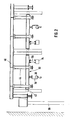
Die dritte Vorrichtung 6 und die vierte Vorrichtung 6 sind nahezu identisch aufgebaut, so daß deren Beschreibung nur einmal erfolgt. Die Vorrichtung 6 besteht hauptsächlich aus einem in Draufsicht im wesentlichen rechteckigen Rahmen 30, vier vertikalen Führungsträgern 32 in den Eckbereichen des Rahmens 30, und einer Vortriebseinheit 34, die am Rahmen 30 befestigt ist und sich parallel zu einem Transportbahnabschnitt 36 der dritten Vorrichtung 6 erstreckt. Der Rahmen 30 befindet sich im wesentlichen in einer horizontalen Ebene. Der Rahmen 30 besteht im wesentlichen aus zwei Längsträgern 38 und vier die Längsträger 38 verbindenden Querträgern 40.The
Insbesondere in Fig. 2 erkennt man, daß an der Unterseite des Rahmens 30 mittig zwischen den beiden Längsträgern 38 der Transportbahnabschnitt 36 befestigt ist. Auf einer Seite sind die Querträger 40 über den dortigen Längsträger 38 hinaus verlängert. Dort ist unter den Querträgern 40 des Rahmens 30, links oder rechts neben und parallel zu dem Transportbahnabschnitt 36, die Vortriebseinheit 34 befestigt.In particular in FIG. 2 it can be seen that the
Jeder Führungsträger 32 besteht aus einem Paar von U-Trägern, die mit ihrer offenen Seiten unter Freilassung eines Spalts nebeneinandergestellt sind. An den beiden Enden sowohl des vordersten als auch des hintersten Querträgers 40 sind Rollen 42 angebracht, die in das Innere des betreffenden Führungsträgerpaars 32 greifen.Each
Die Führungsträger 32 können auch aus einem Rund-, Quadrat- oder Recheckrohr oder einem anderen Profil hergestellt sein. Hierbei sind die Hohlprofile mit einem Schlitz an einer Seite versehen. Anstelle der Rollen 42 können auch Gleitschuhe oder Gleithülsen aus Metall oder Kunststoff zum Einsatz kommen. Bei Einsatz von außen auf den Führungsträgern 32 angeordneten Rollen, Gleitschuhen oder Gleithülsen sind keine Schlitze oder Spalte in den Führungsträgern 32 erforderlich.The guide beams 32 can also be made from a round, square or rectangular tube or another profile. The hollow profiles are provided with a slot on one side. Instead of the
Sowohl am vorderen als auch am hinteren Ende jedes Längsträgers 38 ist eine vertikale, pneumatische Zylinder-Kolben-Einheit 44 befestigt. Jede Zylinder-Kolben-Einheit 44 ist oben an einem massiven Querträger 46 des Vorrichtungsgerüsts befestigt. Mittels der Zylinder-Kolben-Einheiten 44 läßt sich der Rahmen 30 in Vertikalrichtung verfahren, wobei er durch die Rollen 42, Gleitschuhe oder Gleithülsen läng der Führungsträger 32 geführt ist. Mit dem Rahmen 30 bewegen sich der Transportbahnabschnitt 36 und die Vortriebseinheit 34 translatorisch aufwärts und abwärts. Der Rahmen 30 läßt sich relativ zu einer Neutral-Höhenposition, in der der Transportbahnabschnitt 36 mit der anschließenden Transportbahn 8 fluchtet, nach oben und nach unten verfahren.A vertical, pneumatic cylinder-
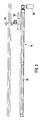
In Fig. 3 erkennt man deutlicher den Aufbau der Vortriebseinheit 34. Die Vortriebseinheit 34 weist hauptsächlich ein geradliniges, langgestrecktes, auf einer Seite längsgeschlitztes Gehäuse 48, eine darin rotierbar angeordnete, in Fig. 3 nicht sichtbare Gewindespindel, einen elektrischen Antriebs-Getriebemotor 50 zum rotierenden Antreiben der Gewindespindel, einen längs des Gehäuses 48 verfahrbaren Schlitten 52, und einen quer zur Längserstreckung des Gehäuses 48 von dem Schlitten 52 wegragenden Arm 54 als Angreifeinrichtung an einem zu zerlegenden Rinderviertel auf. Auf der Gewindespindel sitzt eine oder mehrere Wandermuttern (nicht sichtbar), die mit dem Schlitten 52 verbunden sind, so daß dieser bei Rotation der Gewindespindel in Längsrichtung verfahren wird. Der in Fig. 2 nicht eingezeichnete Arm 54 befindet sich etwas unterhalb des Rohrbahnabschnitts 36.The construction of the
An der Aufhängung 56 (Fig. 2) der Vortriebseinheit 34 ist ein Kraftsensor, insbesondere in Gestalt eines Dehnungsmeßstreifens oder einer elektrischen Wiegezelle, angeordnet, so daß dort laufend erfaßt wird, eine wie große Längskraft die Vortriebseinheit 34 auf den von dem Arm 54 hintergriffenen, ersten Bereich des jeweils zu zerlegenden Rinderviertels ausübt. Über eine nicht eingezeichnete Schaltung wird der Elektromotor 50 abgeschaltet, wenn diese Längskraft einen einstellbaren Schwellwert überschreitet. Wenn die Längskraft wieder unter den eingestellten Schwellwert sinkt, wird der Elektromotor 50 wieder eingeschaltet.A force sensor, in particular in the form of a strain gauge or an electrical weighing cell, is arranged on the suspension 56 (FIG. 2) of the
Bei der in den Fig. 1 bis 5 gezeichneten Anlage sind die dritten Vorrichtungen 6 auf stützen 58 montiert, die auf dem Schlachthofboden ruhen. Es ist alternativ möglich, die Vorrichtungen 6 als an der Schlachthofdecke oder den Schlachthofwänden hängend auszubilden.In the plant shown in FIGS. 1 to 5, the
In Fig. 4 ist eine der Zerlegestationen 6 gezeichnet, wobei die vor der Zeichnungsebene liegende Vortriebseinheit 34 nicht sichtbar ist. Man erkennt die weiter vorn bereits beschriebenen Bauteile: Rahmen 30, Zylinder-Kolben-Einheiten 44 und Transportbahnabschnitt 36. Durch Fig. 4 wird veranschaulicht, daß der Transportbahnabschnitt 36 in Transportrichtung vorn, also links in Fig. 4, über ein teleskopisch längenveränderliches, beidendig gelenkig angeschlossenes Transportbahn-Zwischenstück 60 an die weiterführende Transportbahn angeschlossen ist. Man erkennt ferner, daß zwischen dem in Transportrichtung hinteren, also in Fig. 4 rechten, Ende des Transportbahnabschnitts 36 und der heranführenden Transportbahn 8 eine Schwinge 62 angeordnet ist, die mittels einer pneumatischen Zylinder-Kolben-Einheit 64, die hinter der Zeichnungsebene liegend an dem Rahmen 30 und an der Schwinge 62 angelenkt ist, um ihren in Fig. 4 rechten Endpunkt schwenkbar ist. Durch diese Schwenkbarkeit läßt sich der in Fig. 4 linke Endbereich der Schwinge 62 so weit absenken, daß er sich auf einem niedrigeren Niveau befindet als der Transportbahnabschnitt 36. Außerdem erkennt man am linken Endbereich der Schwinge 62 einen wahlweise in die gezeichnete Aktivstellung oder in eine Passivstellung bringbaren Anschlag 66. Die Schwinge 62 wird in den Ansprüchen und weiter vorn in der Beschreibung als erster Transportbahnabschnitt bezeichnet, und der Transportbahnabschnitt 36 wird in den Ansprüchen und weiter vorn als zweiter Transportbahnabschnitt bezeichnet. Bei dem Rahmen 30, der Schwinge 62 und dem Transportbahnzwischenstück 60 ist die untere Stellung mit unterbrochenen Linien eingezeichnet, während die Neutralstellung mit durchgezogenen Linien eingezeichnet ist.4 shows one of the dismantling
Man kann somit bei unausgefahrener Zylinder-Kolben Einheit 64 den Rahmen 30 und damit den Transportbahnabschnitt 36 gegenüber der mit durchgezogenen Linie gezeichneten Neutralstellung anheben oder absenken, wobei dann das Transportbahnzwischenstück 60 und die Schwinge 62 schräge Lagen einnehmen. Unabhängig von dieser Höhenverfahrbarkeit kann die Schwinge 62 relativ zu dem Transportbahnabschnitt 36 abgesenkt werden.With the cylinder-piston unit 64 not extended, the
Es versteht sich, daß die in Fig. 4 gezeichnete Höhenbeweglichkeit der Schwinge 62 nur eine von mehreren Möglichkeiten ist, den ersten Transportbahnabschnitt höhenbeweglich zu machen. Beispielsweise könnte man statt der schwenkenden Höhenbeweglichkeit eine translatorische Höhenbeweglichkeit des ersten Transportbahnabschnitts vorsehen. Außerdem wäre es beispielsweise möglich, an der Stelle, wo die Schwinge 62 gezeichnet ist, ein Transportbahn-Zwischenstück wie das Transportbahn-Zwischenstück 60 vorzusehen und eine Schwinge 62 bzw. einen translatorisch höhenbeweglichen, ersten Transportbahnabschnitt anstelle des hinteren, also in Fig. 4 rechten, Teils des zweiten Transportbahnabschnitts 36 vorzusehen. Eine weitere Möglichkeit besteht darin, die Schwinge 62 bzw. einen translatorisch höhenbeweglichen, ersten Transportbahnabschnitt nicht dem Rahmen 30 zuzuordnen (wobei sie sich gemeinsam mit dem Rahmen 30 aufwärts und abwärts bewegt), sondern die Schwinge 62 bzw. einen translatorisch höhenbeweglichen, ersten Transportbahnabschnitt an einem geeigneten stationären Schlacht hofträger aufzuhängen. In diesem Fall wurde somit die Schwinge 2 bzw. der translatorisch höhenbewegliche, erste Transportbahnabschnitt seine Höhenbewegung im Prinzip unabhängig von der Höhenbewegung des zweiten Transportbahnabschnitts voll führen.It goes without saying that the height mobility of the
Nachfolgend wird ein typischer Arbeitsablauf beim Zerlegen eines Rinder-Hinterviertels genauer beschrieben, wobei darauf hingewiesen wird, daß der Arbeitsablauf von Zerlegebetrieb zu Zerlegebetrieb beträchtlich variieren kann:A typical workflow for cutting a cattle hind quarter is described in more detail below, although it is pointed out that the workflow can vary considerably from cutting plant to cutting plant:
An der Vorschneidstation 2 wird das Filet herausgeschnitten und das Loch des Schloßknochens (= Beckenknochen) freigeschnitten. Danach werden an der Vorzerlegestation 4 die Dornfortsätze und Rippen getrennt, zum Beispiel mit Hilfe einer schnittiefenregulierbaren, druckluftbetriebenen Säge. Danach wird an der ersten Zerlegestation 6 der Schloßknochen von einem "Oberschale" genannten Fleischstück gelöst und ein Haken in das Loch des Schloßknochens gehängt. Dieser Haken wird auf die Schwinge 62 geschoben. Jetzt wird die Vortriebseinheit 34 eingeschaltet, und deren Angreifteil 54 greift oben an dem Bein des Hinterviertels an, so daß Keulenfleisch mit Röhrenknochen von dem gehaltenen Schloßknochen weggezogen werden. Während dieses Vorgangs schneidet der Zerleger am Schloßknochen entlang. Wärhrend dieses Vorgangs hängt die Hinterhesse (= Hinterbein) des Rinderviertels mittels eines Hakens an dem höhenverfahrbaren Transportabschnitts 36. Am Ende dieses Teils des Zerlegevorgangs hängt der Schloßknochen mit anhaftendem Wirbelkörper an der Schwinge 62, während davon getrennt das Keulenfleisch mit Röhrenknochen und Roastbeef sowie Rippen an dem Trans portbahnabschnitt 36 hängen.At the pre-cutting station 2 the fillet is cut out and the hole of the lock bone (= pelvic bone) is cut free. The spinous processes and ribs are then separated at the
Der Schloßknochen mit anhaftendem Wirbelkörper wird an einer Transportbahnweiche 70 (Fig. 1) ausgeschleust und an einer nicht im Detail gezeichneten und zu beschreibenden Knochenverarbeitungsstation weiterverarbeitet. Das an dem zweiten Haken hängende Teil des Hinterviertels wird zu der zweiten Zerlegestation 6 geschoben. Dort wird in das Keulenfleisch ein Haken eingehängt und dieser auf die dortige Schwinge 62 gehängt. Die zusammenhängenden Röhrenknochen werden mit der dortigen Vortriebseinheit 34 nach vorn gezogen, während der auf der Schwinge 62 hängende Haken zurückgehalten wird. Währenddessen schneidet der Zerleger an den Röhrenknochen entlang. Am Ende dieses Zerlegeschritts bleiben die restlichen Knochenbestandteile des Hinterviertels an dem höhenverfahrbaren Transportbahnabschnitt 36 hängen, während die kompletten Fleischbestandteile des Hinterviertels an dem Haken hängenbleiben, der auf der Schwinge 62 hängt.The lock bone with adhering vertebral body is discharged at a transport track switch 70 (FIG. 1) and processed further at a bone processing station which is not drawn and described in detail. The part of the rear quarter hanging on the second hook is pushed to the
Es ist alternativ möglich, nur eine Zerlegestation 6 statt der beschriebenen zwei hintereinandergeschalteten Zerlegestationen 6 zu haben, insbesondere bei Zerlegeanlagen mit geringerer Leistung in zu zerlegenden Schlachttier-Teilen pro Stunde. Eine weitere Variante besteht darin, die Vorzerlegestation4 zwischen die beiden beschriebenen Zerlegestationen 6 zu setzen.It is alternatively possible to have only one
Ein typischer Bereich der Höhe der Neutralposition des zweiten Transportbahnabschnitts 36 ist 2,3 bis 2,7 m . Ein typischer Bereich der Höhenverfahrbarkeit des zweiten Transportbahnabschnitts 36 ist 10 bis 50 cm entweder nur in einer Richtung aus der Neutralposition heraus oder jeweils um dieses Ausmaß sowohl nach oben als auch nach unten aus der Neutralposition heraus.A typical range of the height of the neutral position of the second
Claims (16)
dadurch gekennzeichnet,
daß die Blockiereinrichtung ein in eine unwirksame Passivstellung bringbarer Anschlag (66) an dem ersten Transportbahnabschnitt (62) ist.2. Plant according to claim 1,
characterized,
that the blocking device is a stop (66) on the first transport track section (62) which can be brought into an inactive passive position.
dadurch gekennzeichnet,
daß die Vortriebseinheit (34) eine Linearantriebseinheit mit einem Elektromotor (50) und einer von diesem antreibbaren Gewindespindel ist.3. Plant according to claim 1 or 2,
characterized,
that the propulsion unit (34) is a linear drive unit with an electric motor (50) and a threaded spindle which can be driven thereby.
dadurch gekennzeichnet,
daß ein Sensor zum Erfassen der von der Vortriebseinheit (34) gelieferten Vortriebskraft und ein aufgrund des Sensorsignals betätigbarer Schalter zum Abschalten des Motors (50) der Vortriebseinheit (34) bei Erreichen einer bestimmten Vortriebskraft vorgesehen sind.4. Plant according to one of claims 1 to 3,
characterized,
that a sensor for detecting the propulsion force supplied by the propulsion unit (34) and a switch which can be actuated on the basis of the sensor signal for switching off of the motor (50) of the propulsion unit (34) are provided when a certain propulsive force is reached.
dadurch gekennzeichnet,
daß die Abschalt-Vortriebskraftschwelle einstellbar ist.5. Plant according to claim 4,
characterized,
that the shutdown propulsive force threshold is adjustable.
dadurch gekennzeichnet,
daß als Sensor ein Dehnungsmeßstreifen oder eine elektrische Wiegezelle vorgesehen ist.6. Plant according to claim 4 or 5,
characterized,
that a strain gauge or an electrical load cell is provided as a sensor.
dadurch gekennzeichnet,
daß die Führung mehrere, im wesentlichen vertikale Träger (32) aufweist.7. Plant according to one of claims 1 to 6,
characterized,
that the guide has a plurality of substantially vertical supports (32).
dadurch gekennzeichnet,
daß zum mechanisierten Verfahren des Rahmens (30) mindestens eine Zylinder-Kolben-Einheit (44) vorgesehen ist.8. Plant according to one of claims 1 to 7,
characterized,
that at least one cylinder-piston unit (44) is provided for the mechanized movement of the frame (30).
dadurch gekennzeichnet,
daß der erste Transportbahnabschnitt (62) derart mit dem Rahmen (30) für den zweiten Transportbahnabschnitt (36) und die Vortriebseinheit (34) verbunden ist, das er beim Höhenverfahren des Rahmens (30) mitgenommen wird.9. Plant according to one of claims 1 to 8,
characterized,
that the first conveyor track section (62) is connected to the frame (30) for the second conveyor track section (36) and the propulsion unit (34) in such a way that it is carried along when the frame (30) is moved upwards.
dadurch gekennzeichnet,
daß zwischen dem Rahmen (30) und dem ersten Transport bahnabschnitt (62) eine Einrichtung (64)zum mechanisierten Höhenbewegen des ersten Transportbahnabschnitts (62) relativ zu dem zweiten Transportbahnabschnitt (36) vorgesehen ist.10. Plant according to claim 9,
characterized,
that between the frame (30) and the first transport track section (62), a device (64) for mechanically moving the first transport track section (62) relative to the second transport track section (36) is provided.
dadurch gekennzeichnet,
daß die Höhenbewegungseinrichtung eine Zylinder-Kolben-Einheit (64) aufweist.11. Plant according to claim 10,
characterized,
that the height-moving device has a cylinder-piston unit (64).
dadurch gekennzeichnet,
daß der erste Transportbahnabschnitt eine Schwinge (62) ist, die um ihr dem zweiten Transportbahnabschnitt (36) entfernteres Ende schwenkbar ist.12. Plant according to one of claims 1 to 11,
characterized,
that the first transport track section is a rocker arm (62) which can be pivoted about its end which is further away from the second transport track section (36).
dadurch gekennzeichnet,
daß der zweite Transportbahnabschnitt (36) mindestens an einem Ende über ein teleskopisch längenveränderliches, gelenkig angeschlossenes Transportbahn-Zwischenstück (60) mit der anschließenden Transportbahn verbunden ist.13. Plant according to one of claims 1 to 12,
characterized,
that the second transport track section (36) is connected at least at one end to the subsequent transport track via a telescopically variable-length, articulated-connected transport track intermediate piece (60).
dadurch gekennzeichnet,
daß in der Transportbahn vor der Zerlegestation (6), die den Rahmen (30) und den ersten Transportbahnabschnitt (62) aufweist, ein dritter höhenverfahrbarer Transportbahnabschnitt (14) als Vorschneidstation (2) vorgesehen ist.14. Plant according to one of claims 1 to 13,
characterized,
that in the transport path in front of the dismantling station (6), which has the frame (30) and the first transport path section (62), a third height-adjustable transport path section (14) is provided as a pre-cutting station (2).
dadurch gekennzeichnet
daß zwischen der Vorschneidstation (2) und einer Zerlegestation (6) ein vierter höhenverfahrbarer Transportbahnabschnitt und eine zugeordnete Schrägzerlegewand (28) als Vorzerlegestation (4) vorgesehen sind.15. Plant according to claim 14,
characterized
that between the pre-cutting station (2) and a dismantling station (6) a fourth height-adjustable transport path section and an associated inclined dismantling wall (28) are provided as a pre-dismantling station (4).
dadurch gekennzeichnet,
daß zwischen einer heran führenden Transportbahn (10) und einer wegführenden Transportbahn (12) zwei hintereinander zu durchlaufende Zerlegestationen (6)`, die jeweils einen Rahmen (30) und einen ersten Transportbahnabschnitt (62) aufweisen, vorgesehen sind.16. Plant according to one of claims 1 to 15,
characterized,
that between a leading transport path (10) and a leading transport path (12) two disassembly stations (6) 'to be passed one behind the other, each having a frame (30) and a first transport path section (62), are provided.
Applications Claiming Priority (2)
| Application Number | Priority Date | Filing Date | Title |
|---|---|---|---|
| DE3937742 | 1989-11-13 | ||
| DE19893937742 DE3937742A1 (en) | 1989-11-13 | 1989-11-13 | PLANT FOR THE EASIER DISASSEMBLY OF Slaughter animal parts, especially cattle quarters |
Publications (2)
| Publication Number | Publication Date |
|---|---|
| EP0443101A2 true EP0443101A2 (en) | 1991-08-28 |
| EP0443101A3 EP0443101A3 (en) | 1991-10-16 |
Family
ID=6393438
Family Applications (1)
| Application Number | Title | Priority Date | Filing Date |
|---|---|---|---|
| EP19900121726 Withdrawn EP0443101A3 (en) | 1989-11-13 | 1990-11-13 | Means for easy deboning of carcass parts, in particular of bovine quarters |
Country Status (2)
| Country | Link |
|---|---|
| EP (1) | EP0443101A3 (en) |
| DE (1) | DE3937742A1 (en) |
Cited By (5)
| Publication number | Priority date | Publication date | Assignee | Title |
|---|---|---|---|---|
| WO1994010847A1 (en) * | 1992-11-17 | 1994-05-26 | Eez-Away Limited | Carcass deboning |
| WO1995002331A1 (en) * | 1993-07-16 | 1995-01-26 | Norling Lars Erik | Method and plant for separating a part from a carcass |
| EP0668018A1 (en) * | 1994-02-23 | 1995-08-23 | Couedic Madore Equipement (Sarl) | Device for sawing-post in a primal cutting station of slaughtered animals |
| EP0882404A3 (en) * | 1997-05-19 | 2000-05-10 | MBA S.r.l. | Compact automatic machine for performing the boning cut on legs of ham |
| FR2794147A1 (en) * | 1999-05-28 | 2000-12-01 | Couedic Madore Equipement | Overhead conveyor e.g. for carcasses in abattoir has variable-level section of track connected to main track by telescopic section |
Families Citing this family (1)
| Publication number | Priority date | Publication date | Assignee | Title |
|---|---|---|---|---|
| WO2004068953A1 (en) * | 2003-02-03 | 2004-08-19 | Mayekawa Mfg.Co., Ltd. | Boning system of meat |
Family Cites Families (7)
| Publication number | Priority date | Publication date | Assignee | Title |
|---|---|---|---|---|
| SE396536B (en) * | 1977-02-23 | 1977-09-26 | Korhonen K J | DEVICE FOR CUTTING PIECE |
| AU526861B2 (en) * | 1978-11-07 | 1983-02-03 | Australian Meat and Livestock Corp., The | Slaughtering sequence |
| DE3011026C2 (en) * | 1980-03-21 | 1986-01-02 | Herta KG Karl Schweisfurth GmbH & Co KG, 4352 Herten | System for dismantling carcasses conveyed on a hanging conveyor to a meat release point |
| US4381582A (en) * | 1980-12-02 | 1983-05-03 | Korhonen K J | Plant and gripping means for cutting up meat |
| FR2554684B1 (en) * | 1983-11-16 | 1987-07-31 | Aubert George | MECHANICAL AND AUTOMATIC DEVICE FOR HANGING BEEF ANIMALS AFTER SLAUGHTERING IN SLAUGHTERHOUSES |
| FR2594003B1 (en) * | 1986-02-12 | 1990-03-23 | Cotentin Viandes | BONING SYSTEM SUSPENDED FROM FOREIGN QUARTERS OF CATTLE. |
| SE457226C (en) * | 1987-04-27 | 1993-02-08 | Norling Lars Erik | METHOD FOR SEPARATING SKELETIC PARTS FROM A CARP |
-
1989
- 1989-11-13 DE DE19893937742 patent/DE3937742A1/en active Granted
-
1990
- 1990-11-13 EP EP19900121726 patent/EP0443101A3/en not_active Withdrawn
Cited By (8)
| Publication number | Priority date | Publication date | Assignee | Title |
|---|---|---|---|---|
| WO1994010847A1 (en) * | 1992-11-17 | 1994-05-26 | Eez-Away Limited | Carcass deboning |
| US5597351A (en) * | 1992-11-17 | 1997-01-28 | Eez-Away Limited | Carcass deboning |
| US5599226A (en) * | 1993-06-16 | 1997-02-04 | Norling; Lars-Erik | Method and plant for separating a part from a carcass |
| WO1995002331A1 (en) * | 1993-07-16 | 1995-01-26 | Norling Lars Erik | Method and plant for separating a part from a carcass |
| EP0668018A1 (en) * | 1994-02-23 | 1995-08-23 | Couedic Madore Equipement (Sarl) | Device for sawing-post in a primal cutting station of slaughtered animals |
| FR2716340A1 (en) * | 1994-02-23 | 1995-08-25 | Couedic Madore Equipement | Device for sawing station in a primary cutting line of slaughter animals. |
| EP0882404A3 (en) * | 1997-05-19 | 2000-05-10 | MBA S.r.l. | Compact automatic machine for performing the boning cut on legs of ham |
| FR2794147A1 (en) * | 1999-05-28 | 2000-12-01 | Couedic Madore Equipement | Overhead conveyor e.g. for carcasses in abattoir has variable-level section of track connected to main track by telescopic section |
Also Published As
| Publication number | Publication date |
|---|---|
| EP0443101A3 (en) | 1991-10-16 |
| DE3937742A1 (en) | 1991-05-16 |
| DE3937742C2 (en) | 1992-07-16 |
Similar Documents
| Publication | Publication Date | Title |
|---|---|---|
| DE69630178T2 (en) | Method and device for processing slaughter poultry | |
| DE60100042T2 (en) | Splitting device with a movable stand | |
| DE2133027C2 (en) | Device for holding animals to be anesthetized | |
| DE3937742C2 (en) | ||
| DE3529205A1 (en) | DEVICE FOR SEPARATING THE HEAD OF Slaughter Animal Bodies, IN PARTICULAR CATTLE | |
| DE69601478T2 (en) | Device for processing carcasses or carcass parts | |
| DE3327968C2 (en) | Method and device for mechanically opening fish, in particular trout, and for removing the entrails | |
| DE3011026C2 (en) | System for dismantling carcasses conveyed on a hanging conveyor to a meat release point | |
| DE60216971T2 (en) | DEVICE AND METHOD FOR STUNNING SLAUGHTERED ANIMALS | |
| EP0212579B2 (en) | Device for cutting up the breasts of carcasses, in particular of cattle or hogs | |
| DE2902521B2 (en) | Device for removing feed from a flat silo | |
| DE1939046C2 (en) | Device for dividing carcasses in two | |
| EP0398219B1 (en) | Step-by-step conveying device, particularly for transport hooks in slaughter-houses | |
| EP1763995B1 (en) | Device and method for grading aquatic animals in a rearing unit | |
| EP0743005B1 (en) | Electrical stunning apparatus | |
| DE69204294T2 (en) | Device for skinning slaughter animals, in particular sheep and goats. | |
| EP0524647B1 (en) | Method and apparatus for slaughtering cattle | |
| DE2807837A1 (en) | BODY CUTTERING FACILITY FOR A Slaughterhouse | |
| DE19501413C2 (en) | Method and device for driving stress-free slaughter animals, especially pigs, into a stunning station of a slaughterhouse | |
| DE3629376C2 (en) | ||
| DE1921059A1 (en) | Cheese crumbler cutter frames for - adaptability and easy handling | |
| DE2050229C3 (en) | Device for slitting animals for slaughter | |
| DE2451010C3 (en) | Combination Battle Street | |
| DE2050230C3 (en) | System for splitting carcasses along the spine | |
| DE2452780A1 (en) | METHOD AND DEVICE FOR CUTTING SEALED ANIMAL |
Legal Events
| Date | Code | Title | Description |
|---|---|---|---|
| PUAI | Public reference made under article 153(3) epc to a published international application that has entered the european phase |
Free format text: ORIGINAL CODE: 0009012 |
|
| PUAL | Search report despatched |
Free format text: ORIGINAL CODE: 0009013 |
|
| AK | Designated contracting states |
Kind code of ref document: A2 Designated state(s): AT CH DE DK LI |
|
| AK | Designated contracting states |
Kind code of ref document: A3 Designated state(s): AT CH DE DK LI |
|
| 17P | Request for examination filed |
Effective date: 19920415 |
|
| STAA | Information on the status of an ep patent application or granted ep patent |
Free format text: STATUS: THE APPLICATION IS DEEMED TO BE WITHDRAWN |
|
| 18D | Application deemed to be withdrawn |
Effective date: 19930602 |