EP0443111A1 - Connecteur pour la connexion d'une colonne avec une barre tubulaire, colonne connectée et ensemble avec au moins une colonne et une barre - Google Patents
Connecteur pour la connexion d'une colonne avec une barre tubulaire, colonne connectée et ensemble avec au moins une colonne et une barre Download PDFInfo
- Publication number
- EP0443111A1 EP0443111A1 EP90122486A EP90122486A EP0443111A1 EP 0443111 A1 EP0443111 A1 EP 0443111A1 EP 90122486 A EP90122486 A EP 90122486A EP 90122486 A EP90122486 A EP 90122486A EP 0443111 A1 EP0443111 A1 EP 0443111A1
- Authority
- EP
- European Patent Office
- Prior art keywords
- column
- jaw
- connecting element
- jaws
- strut
- Prior art date
- Legal status (The legal status is an assumption and is not a legal conclusion. Google has not performed a legal analysis and makes no representation as to the accuracy of the status listed.)
- Granted
Links
Images

Classifications
-
- F—MECHANICAL ENGINEERING; LIGHTING; HEATING; WEAPONS; BLASTING
- F16—ENGINEERING ELEMENTS AND UNITS; GENERAL MEASURES FOR PRODUCING AND MAINTAINING EFFECTIVE FUNCTIONING OF MACHINES OR INSTALLATIONS; THERMAL INSULATION IN GENERAL
- F16B—DEVICES FOR FASTENING OR SECURING CONSTRUCTIONAL ELEMENTS OR MACHINE PARTS TOGETHER, e.g. NAILS, BOLTS, CIRCLIPS, CLAMPS, CLIPS OR WEDGES; JOINTS OR JOINTING
- F16B7/00—Connections of rods or tubes, e.g. of non-circular section, mutually, including resilient connections
- F16B7/04—Clamping or clipping connections
- F16B7/044—Clamping or clipping connections for rods or tubes being in angled relationship
-
- A—HUMAN NECESSITIES
- A47—FURNITURE; DOMESTIC ARTICLES OR APPLIANCES; COFFEE MILLS; SPICE MILLS; SUCTION CLEANERS IN GENERAL
- A47B—TABLES; DESKS; OFFICE FURNITURE; CABINETS; DRAWERS; GENERAL DETAILS OF FURNITURE
- A47B13/00—Details of tables or desks
- A47B13/02—Underframes
- A47B13/06—Underframes of metal
-
- F—MECHANICAL ENGINEERING; LIGHTING; HEATING; WEAPONS; BLASTING
- F16—ENGINEERING ELEMENTS AND UNITS; GENERAL MEASURES FOR PRODUCING AND MAINTAINING EFFECTIVE FUNCTIONING OF MACHINES OR INSTALLATIONS; THERMAL INSULATION IN GENERAL
- F16B—DEVICES FOR FASTENING OR SECURING CONSTRUCTIONAL ELEMENTS OR MACHINE PARTS TOGETHER, e.g. NAILS, BOLTS, CIRCLIPS, CLAMPS, CLIPS OR WEDGES; JOINTS OR JOINTING
- F16B12/00—Jointing of furniture or the like, e.g. hidden from exterior
- F16B12/40—Joints for furniture tubing
-
- F—MECHANICAL ENGINEERING; LIGHTING; HEATING; WEAPONS; BLASTING
- F16—ENGINEERING ELEMENTS AND UNITS; GENERAL MEASURES FOR PRODUCING AND MAINTAINING EFFECTIVE FUNCTIONING OF MACHINES OR INSTALLATIONS; THERMAL INSULATION IN GENERAL
- F16B—DEVICES FOR FASTENING OR SECURING CONSTRUCTIONAL ELEMENTS OR MACHINE PARTS TOGETHER, e.g. NAILS, BOLTS, CIRCLIPS, CLAMPS, CLIPS OR WEDGES; JOINTS OR JOINTING
- F16B7/00—Connections of rods or tubes, e.g. of non-circular section, mutually, including resilient connections
- F16B7/04—Clamping or clipping connections
- F16B7/044—Clamping or clipping connections for rods or tubes being in angled relationship
- F16B7/0446—Clamping or clipping connections for rods or tubes being in angled relationship for tubes using the innerside thereof
- F16B7/0473—Clamping or clipping connections for rods or tubes being in angled relationship for tubes using the innerside thereof with hook-like parts gripping, e.g. by expanding, behind the flanges of a profile
Definitions
- the invention relates to a connecting element for connecting a column with a strut according to the preamble of claim 1, a column to be connected according to the preamble of claim 8 and a frame with at least one column and a tubular strut according to the preamble of claim 10.
- a connecting element for connecting a column to a strut is known from DE-OS 36 02 686.
- the hook ends of four hook parts adjustable with a screw engage in two slots in a column designed as a square tube.
- the hook parts are fastened in the strut with a safety bolt and can be swiveled around a swivel axis by turning the screw.
- the hook ends have bevelled surfaces. By turning the screw, the hook ends are spread apart against the opposite hole edges of the slots, the beveled surfaces being the end face of the Pull the strut against the column and thus firmly connect the strut to the column.
- Another generic connecting element is known from GB-A 2 125 511.
- This known connecting element is constructed analogously to the connecting element known from DE-OS 36 02 686 and has u. a. Instead of the screw, a plate-shaped closing element for spreading the hook ends apart. Instead of four hook parts, only two are used.
- the column is designed as a profile tube.
- the known connecting elements require slots in the column in order to be able to insert the hook ends for fastening.
- the production of these slots without deformation of the column is complex.
- Several struts can be attached to a column at the same height, but only at an angle of 90 ° to each other.
- the invention has for its object to provide a simple connecting element for connecting a column with a tubular strut, which avoids the above disadvantages.
- the connecting element 1 shown in FIG . 1 for connecting a vertical cylindrical tubular column 3 to a tubular horizontal hollow cylindrical strut 5 has two jaws 7 and 9 , a screw 11 with a conical head attachment 12 and a spacer 13 .
- the two jaws 7 and 9 are in the left end of the strut 5 and are held with the screw 11 diametrically opposite each other in the longitudinal direction of the strut.
- Each of the jaws 7 and 9 has Two end faces 15a and 15b or 17a and 17b lying in one plane , which are separated from each other by a hook-like extension 19a or 19b and 21a or 21b .
- a hook-like extension 19a or 19b and 21a or 21b As can be seen in the top view of the jaw 7 in FIG.
- the shape of the end faces 15a and 15b is adapted to the casing of the column 3 ; the end faces 17a and 17b of the jaw 9 are formed analogously.
- the cross sections of the lugs 19a and 19b are mirror images of those of the lugs 21a and 21b .
- the side 23 or 25 of the jaw 7 or 9 facing the inner surface of the strut 5 is arched, as can be seen in particular in its perspective illustration in FIGS. 3 and 4 , and is therefore matched to the inner surface of the strut 5 .
- the through bores 27 and 29 are not located in the center 31 of the jaw length, but are arranged offset to this by a distance d ; see Figure 2 . In their position of use, the through holes 27 and 29 are aligned.
- the through bore 27 is provided with a thread in its non-expanded part.
- the diameter of the through bore 29 corresponds to the outer thread diameter of the threaded bore 27 plus a tolerance.
- the jaw 9 is a mirror image of the jaw 7 , but additionally has two recesses 33a and 33b, into which the spacer 13 can optionally be inserted captively with a weak "clamping fit"; in Figure 1 , the spacer 13 is seated in the recess 33b .
- the strut 5 has set back at each end two countersunk, opposite, aligned holes 34a and 34b , only the holes 34a and 34b being shown at the left end of the strut 5 (FIG. 1) .
- the distance between the holes 34a and 34b from the end of the strut is selected such that that, as shown in Figure 1 , there is a space between the strut end and the column jacket, which the two jaws 7 and 9 bridge in the assembled state.
- the diameter of the holes 34a and 34b corresponds to the average diameter of the conical head extension 12 of the screw 11 .
- the column 3 has two coaxial spaced a distance from each other circumferential grooves 35 and 37th
- the profile of the grooves 35 and 37 is mirror images of one another.
- the adjacent side walls 39a and 39b of the grooves 35 and 37 form an acute angle with the casing of the column 3 , while each of the other side walls 41a and 41b forms an obtuse angle.
- the respective groove bottom 43a or 43b is coaxial to the column jacket.
- the distance a between the two grooves 35 and 37 is selected such that it corresponds to the distance between the two adjacent sides 45a and 46a of the lugs 19a and 21a of the jaws 7 and 9 in the assembled state, as can be seen in FIG .
- the side walls 45a and 46b and the front surfaces 49a and 50a of the lugs 19a and 21a are designed to match the grooves 35 and 37 .
- the side wall 45c and the front surface 49b and the side wall 46c and the front surface 50b of the extension 19b and 21b are formed analogously .
- the distance b between the lugs 19b and 21b is greater than the distance a between the other two lugs 19a and 21a .
- the side walls 45b and 45d and 46b and 46d opposite the side walls 45a and 45c and 46a and 46c are formed approximately parallel to the side walls 41a and 41b of the grooves 35 and 37 in order to transmit the greatest possible force via the shoulders 19a and 21a and 19b and 21b via the grooves 35 and 37 on the column 3 .
- the spacers 13 are pressed into the recess 33b of the jaw 9 .
- the jaws 7 and 9 are in the left end of the The strut 5 is inserted in such a way that, as shown in FIG. 1 , the jaw 7 is at the top and the jaw 9 is at the bottom.
- the screw 11 is pushed from below through the hole 34b in the strut 5 through the through hole 29 in the jaw 9 and screwed into the threaded bore 27 of the jaw 7 until it comes through the hole 34a of the strut 5b .
- the jaws 7 and 9 located in the strut 5 are then hung with their projections 19a and 21a into the grooves 35 and 37 of the column 3 and the screw 11 is tightened.
- the jaw 7 By tightening the screw 11 , the jaw 7 is pulled against the jaw 9 and thereby the sides 45a and 46a of the lugs 19a and 21a are pulled against the side walls 39a and 39b of the grooves 35 and 37 . Due to the spacer 13 located between the two jaws 7 and 9 , the jaws 7 and 9 are pulled by the screw 11 against the groove side walls 39a and 39b without delay. By screwing the screw 11 into the jaw 7 , the jaw 9 is pulled by the jaw 7 against the wall of the strut 5 due to the head end 12 of the screw 11 held by the hole 34b .
- the connecting element 1 is non-positively and positively connected to the strut 5 by the jaw 9 pressed against the inside of the strut 5 via the conical screw attachment 12 .
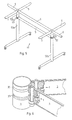
- Certain column structures with struts require columns with two different diameters, such as. B. in Figure 5 for a frame 51 consisting of two nested columns 52a and 52b.
- the two grooves 53 are then made at a distance b .
- the two jaws 7 and 9 are inserted into the strut 5 such that the lugs 19b and 21b look out of the strut 5 .
- the spacer 13 is here in the Recess 33a pressed in. The rest of the assembly is done as described above.
- the side walls 45c and 46c of the lugs 19b and 21b then rest on the sides of the grooves which are analogous to the sides 39a and 39b .
- the distance between the two lugs 19b and 21b is greater by the distance d from the center 31 than the distance between the lugs 19a and 21a , this results in the larger diameter of the columns 52a with struts 5 of the same length in the overall construction the frame 51 balanced again.
- the distance d corresponds to the difference between the two column radii.
- a false assembly, ie connecting the lugs 19 b and 21b at the thin column 3 to make it impossible, the distance b is of the lugs 19b and 21b greater than the distance a of the projections 19a and 21a are selected.
- both struts 5 can be fastened to a column 3 at almost any angle.
- the minimum usable angle depends on the diameter ratio of the strut 5 to the column 3 , and is approximately 54 ° with the same diameter of the column and strut.
- both struts 5 are shown in longitudinal section along a plane in FIG. 6 , in which the screw axis and the strut axis lie.
- an elliptical column and a solid column can also be used.
- a column consisting of a square tube (hexagonal tube, ...) can also be used, in the side surfaces of which horizontal grooves corresponding to grooves 35 and 37 are milled. If a square tube is used, however, it is no longer possible to connect the struts to the column at any angle; only one strut can be attached to each square side perpendicular to the square side.
- any strut (elliptical, square, hexagonal, ...) can be used. It is only necessary to adjust the sides 23 and 25 of the jaws according to the inner surface of the struts.
- the grooves 35 and 37 and hereby fittingly, also the lugs 19a and 19b as well as 21a and 21b can be made of different widths in order to achieve a clear position of the strut 5 on the column 3 ; the position of the screw head is hereby clearly defined.
- connecting element makes it possible to use columns which can be pushed into one another, since the connecting element does not protrude into the interior of the column. Furthermore, columns with two different diameters can be used in a frame without having to adjust the length of the struts.
- the grooves on the outside of the columns can be manufactured inexpensively in an easy-to-use turning process. Elaborate punching or sawing work, such as in the production of the known connecting elements, in which there is a risk of column warping, is not necessary. In addition, inexpensive, easy-to-work round material can be used instead of the expensive profile material.
- Another advantage of the connecting element according to the invention is the possibility of attaching struts at almost any angle, which results in additional design options in the manufacture of frames.
Landscapes
- Engineering & Computer Science (AREA)
- General Engineering & Computer Science (AREA)
- Mechanical Engineering (AREA)
- Mutual Connection Of Rods And Tubes (AREA)
- Joining Of Building Structures In Genera (AREA)
- Rod-Shaped Construction Members (AREA)
Applications Claiming Priority (2)
| Application Number | Priority Date | Filing Date | Title |
|---|---|---|---|
| CH314/90A CH680525A5 (fr) | 1990-01-31 | 1990-01-31 | |
| CH314/90 | 1990-01-31 |
Publications (2)
| Publication Number | Publication Date |
|---|---|
| EP0443111A1 true EP0443111A1 (fr) | 1991-08-28 |
| EP0443111B1 EP0443111B1 (fr) | 1994-03-02 |
Family
ID=4184183
Family Applications (1)
| Application Number | Title | Priority Date | Filing Date |
|---|---|---|---|
| EP90122486A Expired - Lifetime EP0443111B1 (fr) | 1990-01-31 | 1990-11-26 | Connecteur pour la connexion d'une colonne avec une barre tubulaire, colonne connectée et ensemble avec au moins une colonne et une barre |
Country Status (6)
| Country | Link |
|---|---|
| EP (1) | EP0443111B1 (fr) |
| AT (1) | ATE102299T1 (fr) |
| CH (1) | CH680525A5 (fr) |
| DE (1) | DE59004801D1 (fr) |
| DK (1) | DK0443111T3 (fr) |
| ES (1) | ES2052138T3 (fr) |
Cited By (4)
| Publication number | Priority date | Publication date | Assignee | Title |
|---|---|---|---|---|
| DE102005016310A1 (de) * | 2005-04-09 | 2006-10-12 | Storebest Gmbh & Co. Kg | Personenführung |
| DE19828746B4 (de) * | 1998-06-27 | 2008-03-06 | Wanzl Metallwarenfabrik Gmbh | Personenführung |
| WO2008049244A1 (fr) * | 2006-10-24 | 2008-05-02 | Vitra Patente Ag | Montage de structure d'une table |
| DE202008012023U1 (de) | 2008-09-10 | 2008-12-11 | Vitra Patente Ag | Tischkonstruktion |
Citations (6)
| Publication number | Priority date | Publication date | Assignee | Title |
|---|---|---|---|---|
| DE2108342A1 (de) * | 1971-02-22 | 1972-09-07 | Conrad Martin Kg | Rohrverbindung |
| GB2125511A (en) * | 1982-07-30 | 1984-03-07 | Fehlbaum & Co | Support frame elements |
| EP0157993A1 (fr) * | 1984-04-12 | 1985-10-16 | C.P.M. Costruzioni Progettazione Meccanica S.d.f. tra PAPARO Elio & BILIOTTI Leonardo | Structure réticulaire, tridimensionnelle, à montants par éléments |
| US4574552A (en) * | 1981-10-30 | 1986-03-11 | Protoned B.V | Support frame |
| DE3602686A1 (de) * | 1986-01-30 | 1987-08-06 | Osterloh Fa Fritz | Verbindungselement fuer gestelle |
| FR2602838A1 (fr) * | 1986-08-05 | 1988-02-19 | Sepimex Sa | Dispositif d'assemblage en angle d'au moins un element sur un support, notamment d'au moins un profile sur un profile-support |
-
1990
- 1990-01-31 CH CH314/90A patent/CH680525A5/de not_active IP Right Cessation
- 1990-11-26 DE DE90122486T patent/DE59004801D1/de not_active Expired - Lifetime
- 1990-11-26 ES ES90122486T patent/ES2052138T3/es not_active Expired - Lifetime
- 1990-11-26 EP EP90122486A patent/EP0443111B1/fr not_active Expired - Lifetime
- 1990-11-26 DK DK90122486.5T patent/DK0443111T3/da active
- 1990-11-26 AT AT90122486T patent/ATE102299T1/de not_active IP Right Cessation
Patent Citations (6)
| Publication number | Priority date | Publication date | Assignee | Title |
|---|---|---|---|---|
| DE2108342A1 (de) * | 1971-02-22 | 1972-09-07 | Conrad Martin Kg | Rohrverbindung |
| US4574552A (en) * | 1981-10-30 | 1986-03-11 | Protoned B.V | Support frame |
| GB2125511A (en) * | 1982-07-30 | 1984-03-07 | Fehlbaum & Co | Support frame elements |
| EP0157993A1 (fr) * | 1984-04-12 | 1985-10-16 | C.P.M. Costruzioni Progettazione Meccanica S.d.f. tra PAPARO Elio & BILIOTTI Leonardo | Structure réticulaire, tridimensionnelle, à montants par éléments |
| DE3602686A1 (de) * | 1986-01-30 | 1987-08-06 | Osterloh Fa Fritz | Verbindungselement fuer gestelle |
| FR2602838A1 (fr) * | 1986-08-05 | 1988-02-19 | Sepimex Sa | Dispositif d'assemblage en angle d'au moins un element sur un support, notamment d'au moins un profile sur un profile-support |
Cited By (6)
| Publication number | Priority date | Publication date | Assignee | Title |
|---|---|---|---|---|
| DE19828746B4 (de) * | 1998-06-27 | 2008-03-06 | Wanzl Metallwarenfabrik Gmbh | Personenführung |
| DE102005016310A1 (de) * | 2005-04-09 | 2006-10-12 | Storebest Gmbh & Co. Kg | Personenführung |
| DE102005016310B4 (de) * | 2005-04-09 | 2007-04-05 | Storebest Gmbh & Co. Kg | Personenführung |
| WO2008049244A1 (fr) * | 2006-10-24 | 2008-05-02 | Vitra Patente Ag | Montage de structure d'une table |
| DE202008012023U1 (de) | 2008-09-10 | 2008-12-11 | Vitra Patente Ag | Tischkonstruktion |
| EP2163170A2 (fr) | 2008-09-10 | 2010-03-17 | Vitra Patente AG | Construction de table |
Also Published As
| Publication number | Publication date |
|---|---|
| EP0443111B1 (fr) | 1994-03-02 |
| ATE102299T1 (de) | 1994-03-15 |
| CH680525A5 (fr) | 1992-09-15 |
| DE59004801D1 (de) | 1994-04-07 |
| DK0443111T3 (da) | 1994-03-28 |
| ES2052138T3 (es) | 1994-07-01 |
Similar Documents
| Publication | Publication Date | Title |
|---|---|---|
| EP1259738B1 (fr) | Dispositif de connexion de profiles | |
| EP2685111B1 (fr) | Dispositif de serrage de connexion amovibles de deux pièces profilées | |
| DE2618442C2 (de) | Stütze für ein Geländer oder dergleichen | |
| EP1135616B1 (fr) | Assemblage en t de deux barreaux profiles | |
| DE2348239A1 (de) | Gestellanordnung | |
| EP0144030A2 (fr) | Tuyau profilé pour la réalisation de contructions facilement montables et démontables | |
| EP0694659B1 (fr) | Echafaudage | |
| DE69210796T3 (de) | Klammer, insbesondere zur Befestigung von Heizkörpern | |
| EP0976891B1 (fr) | Système de construction | |
| EP0443111B1 (fr) | Connecteur pour la connexion d'une colonne avec une barre tubulaire, colonne connectée et ensemble avec au moins une colonne et une barre | |
| DE10225403A1 (de) | Ständerwerk | |
| DE19756869A1 (de) | Dämmvorrichtung mit Dammbalkenstütze und Verriegelungseinrichtung | |
| DE4110185C1 (fr) | ||
| DE69512375T2 (de) | Vorrichtung um einen Heizkörper an einer Unterlage zu befestigen | |
| EP0287070A1 (fr) | Arrangement de raccordement amovible de deux tubes bout à bout | |
| DE19834372C1 (de) | Profilrohr für die Herstellung kurzzeitiger Aufbauten | |
| DE9212546U1 (de) | Rohrgestell | |
| CH719422A2 (de) | Verbindungseinrichtung für Tragelemente vorzugsweise für ein Traggerüst. | |
| CH693350A5 (de) | Ausziehrahmen für Hochschränke. | |
| DE3616453A1 (de) | Tuerzarge | |
| DE9407718U1 (de) | Mittel zum Befestigen und Verbinden zweier engbenachbart zueinander angeordneter Langprofile | |
| DE29721303U1 (de) | Vorrichtung zur Befestigung eines vertikale und horizontale Streben umfassenden Gitterfeldes an einem Zaunpfahl | |
| DE3517306A1 (de) | Vorrichtung zum ausrichten nebeneinander angeordneter schalungselemente | |
| EP1036945B1 (fr) | Kit comprenant un dispositif pour la fixation réglable de panneaux fixes ou mobiles | |
| DE29505791U1 (de) | Befestigungselement zum lösbaren Verbinden eines Mehrkantrohres |
Legal Events
| Date | Code | Title | Description |
|---|---|---|---|
| PUAI | Public reference made under article 153(3) epc to a published international application that has entered the european phase |
Free format text: ORIGINAL CODE: 0009012 |
|
| AK | Designated contracting states |
Kind code of ref document: A1 Designated state(s): AT BE CH DE DK ES FR GB GR IT LI LU NL SE |
|
| 17P | Request for examination filed |
Effective date: 19910916 |
|
| 17Q | First examination report despatched |
Effective date: 19920427 |
|
| GRAA | (expected) grant |
Free format text: ORIGINAL CODE: 0009210 |
|
| AK | Designated contracting states |
Kind code of ref document: B1 Designated state(s): AT BE CH DE DK ES FR GB GR IT LI LU NL SE |
|
| REF | Corresponds to: |
Ref document number: 102299 Country of ref document: AT Date of ref document: 19940315 Kind code of ref document: T |
|
| REG | Reference to a national code |
Ref country code: DK Ref legal event code: T3 |
|
| GBT | Gb: translation of ep patent filed (gb section 77(6)(a)/1977) |
Effective date: 19940301 |
|
| ITF | It: translation for a ep patent filed | ||
| REF | Corresponds to: |
Ref document number: 59004801 Country of ref document: DE Date of ref document: 19940407 |
|
| ET | Fr: translation filed | ||
| REG | Reference to a national code |
Ref country code: ES Ref legal event code: FG2A Ref document number: 2052138 Country of ref document: ES Kind code of ref document: T3 |
|
| REG | Reference to a national code |
Ref country code: GR Ref legal event code: FG4A Free format text: 3011711 |
|
| PLBE | No opposition filed within time limit |
Free format text: ORIGINAL CODE: 0009261 |
|
| STAA | Information on the status of an ep patent application or granted ep patent |
Free format text: STATUS: NO OPPOSITION FILED WITHIN TIME LIMIT |
|
| EAL | Se: european patent in force in sweden |
Ref document number: 90122486.5 |
|
| 26N | No opposition filed | ||
| REG | Reference to a national code |
Ref country code: CH Ref legal event code: PFA Free format text: U. SCHAERER SOEHNE AG (USM) TRANSFER- USM HOLDING AG |
|
| REG | Reference to a national code |
Ref country code: GB Ref legal event code: IF02 |
|
| REG | Reference to a national code |
Ref country code: FR Ref legal event code: CD Ref country code: FR Ref legal event code: CA |
|
| NLT1 | Nl: modifications of names registered in virtue of documents presented to the patent office pursuant to art. 16 a, paragraph 1 |
Owner name: USM HOLDING AG |
|
| PG25 | Lapsed in a contracting state [announced via postgrant information from national office to epo] |
Ref country code: IT Free format text: LAPSE BECAUSE OF NON-PAYMENT OF DUE FEES Effective date: 20071126 |
|
| PGFP | Annual fee paid to national office [announced via postgrant information from national office to epo] |
Ref country code: ES Payment date: 20091126 Year of fee payment: 20 Ref country code: LU Payment date: 20091120 Year of fee payment: 20 Ref country code: SE Payment date: 20091116 Year of fee payment: 20 Ref country code: DE Payment date: 20091028 Year of fee payment: 20 Ref country code: DK Payment date: 20091124 Year of fee payment: 20 Ref country code: AT Payment date: 20091124 Year of fee payment: 20 Ref country code: CH Payment date: 20091022 Year of fee payment: 20 |
|
| PGFP | Annual fee paid to national office [announced via postgrant information from national office to epo] |
Ref country code: NL Payment date: 20091130 Year of fee payment: 20 |
|
| PGFP | Annual fee paid to national office [announced via postgrant information from national office to epo] |
Ref country code: GB Payment date: 20091110 Year of fee payment: 20 Ref country code: FR Payment date: 20091116 Year of fee payment: 20 |
|
| PGFP | Annual fee paid to national office [announced via postgrant information from national office to epo] |
Ref country code: BE Payment date: 20091126 Year of fee payment: 20 Ref country code: GR Payment date: 20091130 Year of fee payment: 20 |
|
| BE20 | Be: patent expired |
Owner name: *USM HOLDING A.G. Effective date: 20101126 |
|
| REG | Reference to a national code |
Ref country code: CH Ref legal event code: PL |
|
| REG | Reference to a national code |
Ref country code: NL Ref legal event code: V4 Effective date: 20101126 |
|
| REG | Reference to a national code |
Ref country code: DK Ref legal event code: EUP |
|
| REG | Reference to a national code |
Ref country code: GB Ref legal event code: PE20 Expiry date: 20101125 |
|
| PG25 | Lapsed in a contracting state [announced via postgrant information from national office to epo] |
Ref country code: NL Free format text: LAPSE BECAUSE OF EXPIRATION OF PROTECTION Effective date: 20101126 |
|
| EUG | Se: european patent has lapsed | ||
| REG | Reference to a national code |
Ref country code: ES Ref legal event code: FD2A Effective date: 20110225 |
|
| PG25 | Lapsed in a contracting state [announced via postgrant information from national office to epo] |
Ref country code: GB Free format text: LAPSE BECAUSE OF EXPIRATION OF PROTECTION Effective date: 20101125 |
|
| PG25 | Lapsed in a contracting state [announced via postgrant information from national office to epo] |
Ref country code: ES Free format text: LAPSE BECAUSE OF EXPIRATION OF PROTECTION Effective date: 20101127 |
|
| PGFP | Annual fee paid to national office [announced via postgrant information from national office to epo] |
Ref country code: IT Payment date: 20091124 Year of fee payment: 20 |
|
| PGRI | Patent reinstated in contracting state [announced from national office to epo] |
Ref country code: IT Effective date: 20110616 |
|
| PG25 | Lapsed in a contracting state [announced via postgrant information from national office to epo] |
Ref country code: DE Free format text: LAPSE BECAUSE OF EXPIRATION OF PROTECTION Effective date: 20101126 |