EP0443147A2 - Procédé et dispositif pour réguler/commander la stabilité de marche d'un moteur à combustion interne - Google Patents
Procédé et dispositif pour réguler/commander la stabilité de marche d'un moteur à combustion interne Download PDFInfo
- Publication number
- EP0443147A2 EP0443147A2 EP19900124327 EP90124327A EP0443147A2 EP 0443147 A2 EP0443147 A2 EP 0443147A2 EP 19900124327 EP19900124327 EP 19900124327 EP 90124327 A EP90124327 A EP 90124327A EP 0443147 A2 EP0443147 A2 EP 0443147A2
- Authority
- EP
- European Patent Office
- Prior art keywords
- control
- smooth running
- control difference
- value
- difference
- Prior art date
- Legal status (The legal status is an assumption and is not a legal conclusion. Google has not performed a legal analysis and makes no representation as to the accuracy of the status listed.)
- Granted
Links
Images


Classifications
-
- F—MECHANICAL ENGINEERING; LIGHTING; HEATING; WEAPONS; BLASTING
- F02—COMBUSTION ENGINES; HOT-GAS OR COMBUSTION-PRODUCT ENGINE PLANTS
- F02D—CONTROLLING COMBUSTION ENGINES
- F02D41/00—Electrical control of supply of combustible mixture or its constituents
- F02D41/02—Circuit arrangements for generating control signals
- F02D41/14—Introducing closed-loop corrections
- F02D41/16—Introducing closed-loop corrections for idling
-
- F—MECHANICAL ENGINEERING; LIGHTING; HEATING; WEAPONS; BLASTING
- F02—COMBUSTION ENGINES; HOT-GAS OR COMBUSTION-PRODUCT ENGINE PLANTS
- F02D—CONTROLLING COMBUSTION ENGINES
- F02D41/00—Electrical control of supply of combustible mixture or its constituents
- F02D41/02—Circuit arrangements for generating control signals
- F02D41/04—Introducing corrections for particular operating conditions
- F02D41/08—Introducing corrections for particular operating conditions for idling
-
- F—MECHANICAL ENGINEERING; LIGHTING; HEATING; WEAPONS; BLASTING
- F02—COMBUSTION ENGINES; HOT-GAS OR COMBUSTION-PRODUCT ENGINE PLANTS
- F02D—CONTROLLING COMBUSTION ENGINES
- F02D41/00—Electrical control of supply of combustible mixture or its constituents
- F02D41/02—Circuit arrangements for generating control signals
- F02D41/14—Introducing closed-loop corrections
- F02D41/1497—With detection of the mechanical response of the engine
- F02D41/1498—With detection of the mechanical response of the engine measuring engine roughness
-
- F—MECHANICAL ENGINEERING; LIGHTING; HEATING; WEAPONS; BLASTING
- F02—COMBUSTION ENGINES; HOT-GAS OR COMBUSTION-PRODUCT ENGINE PLANTS
- F02D—CONTROLLING COMBUSTION ENGINES
- F02D2200/00—Input parameters for engine control
- F02D2200/02—Input parameters for engine control the parameters being related to the engine
- F02D2200/10—Parameters related to the engine output, e.g. engine torque or engine speed
- F02D2200/1015—Engines misfires
Definitions
- the invention relates to a method and a device for regulating / controlling the smooth running of an internal combustion engine according to the preambles of the independent claims.
- Such a method and such a device for regulating / controlling the smooth running of an internal combustion engine is known from DE-OS 33 36 028 (US-A-4 688 535).
- the method described there eliminates vibrations of the vehicle in the lower speed range, especially when idling. These vibrations are also called shaking and are based, among other things, on manufacturing tolerances. These manufacturing tolerances mean that different quantities are metered into individual cylinders. The vibrations are eliminated by assigning a control to each cylinder, which regulates the fuel metering for smooth running.
- vibrations occur which cannot be compensated for by a method and a device according to the prior art. It is even the case that the vibrations can be amplified by the smooth running control.
- the invention is based, to eliminate all vibrations occurring in a system for regulating / controlling the smooth running of an internal combustion engine of the type mentioned. This object is achieved by the features characterized in claim 1.
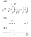
- FIG. 1 shows schematically a fuel metering device.
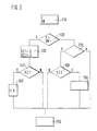
- FIG. 2 shows the individual areas in which the smooth running control or control is active.
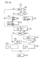
- FIG. 3 shows a rough flow diagram of the method according to the invention.
- Figures 4a and 4b show a detailed flow chart.
- Figure 5 various signal profiles are entered in a diagram.
- the fuel metering device is shown schematically in FIG.
- An internal combustion engine 10 with a plurality of cylinders receives fuel from a fuel pump 20.
- An electronic control device 30 calculates control signals for the fuel pump 20 depending on various input variables 35 and the output signals of a sensor 40.
- a sensor 40 detects the pulses triggered by a segment wheel 50 arranged on the crankshaft.
- the torque generated by the internal combustion engine is transmitted directly or via a two-mass flywheel 60 to the drive train 70 of the motor vehicle.
- the electronic control unit 30 calculates a basic fuel quantity and a correction fuel quantity depending on various variables 35.
- the function of the electronic control unit 30 is e.g. described in detail in DE-OS 36 04 904 or in DE-OS 33 36 028.
- the correction fuel quantities are continuously determined, stored and added to the basic fuel quantity in the corresponding cylinder.
- the amount of correction fuel can take positive or negative values.
- the smoothness is controlled, the correction fuel quantities for the individual cylinders are no longer recalculated. In this case, the stored values are added to the basic fuel quantity.
- the smooth running control is only activated in idle mode. Outside of idling there is a smooth running control or the fuel metering takes place independently of the smooth running. These different areas are shown by way of example in FIG. 2a and FIG. 2b.
- the idle speed control is active in the area of the idling speed LLN, whose value is usually around 700 revolutions per minute. Regulation takes place only in a speed range between approx. 550 and 850 revolutions per minute. In the remaining speed ranges, only smooth running is controlled.
- the smooth running program no longer has any advantages above this limit speed. This is usually the case at around 1,500 revolutions per minute.
- other operating parameters can be used instead of the speed.
- a quantity is, for example, the amount of fuel injected per stroke.
- the smooth running control is only active with an injected fuel quantity between 3 mg / stroke and 11 mg / stroke.
- the areas in which the smooth running control is active depend on the idling speed. Since different types of internal combustion engines also have different idling speeds, the ranges deviate from the above values depending on the type of internal combustion engine.
- vibrations with a very high amplitude and / or certain frequencies occur in the motor vehicle internal combustion engine system, the case may arise that these vibrations cannot be compensated for by the smooth running control. This is particularly the case if the vehicle is equipped with a dual mass flywheel. This dual mass flywheel has different resonance frequencies depending on the operating conditions. If these resonance frequencies are excited, these vibrations are transmitted to the entire motor vehicle internal combustion engine system. If these vibrations have a frequency F which is equal to the crankshaft frequency or 1.5 times the crankshaft frequency, these vibrations disturb the smooth-running controller. For example, the case that the amount of correction fuel is continuously increased, although this is not currently necessary. The vibrations are amplified by the increased correction quantities. In this case, the smooth running control must be switched off.
- FIG. 3 shows a rough flow diagram of the method according to the invention, with which such vibrations can be avoided.
- a first step / 310 the oscillation frequency F or the control difference DN, ie the difference between the setpoint and actual value, is recorded.
- An interrogation unit 320 recognizes whether the control difference DN or the oscillation frequency F exceeds a certain value.
- the smooth running controller is switched off in step 330. This means that the smoothness control is no longer active, but only smoothness control takes place.
- two time counters VZ1 and VZ2 are initialized. In the query unit 340, the first time counter VZ1 is used to query whether a waiting time has already expired. This time query ensures that further measures are taken if the vibrations last longer than a predetermined time.
- step 360 If the measurement of the oscillation frequency F reveals that only crank shaft frequencies occur during a number of crankshaft revolutions or over a predetermined period of time, further measures are initiated in step 360. Such measures can include increasing the idle speed, zeroing the integrators of the PI controller or deleting the stored correction amounts. A speed increase between 50 and 100 revolutions per minute has proven to be a favorable value. This increase in speed can bring the system out of the resonance range. If crankshaft frequencies no longer occur, the idle speed is set to the previous value.
- query 370 is used to check whether the control has been switched off until now.
- the program ends with step 350.
- an inquiry 380 is made as to whether a further waiting time VZ2 has elapsed. If this waiting time has already expired, the controller is switched on again in step 390. If the waiting time has not yet expired, the program continues with the controller switched off. Due to this further waiting time a too quick switch back from control to regulation operation prevented. The switch from control to regulating operation takes place only after the waiting time VZ2 or after a number of speed pulses after the control difference DN or the oscillation frequency falls below a certain value again.
- step 400 the smoothness target values and the smoothness actual values are calculated. This calculation is e.g. B. in DE-OS 33 36 028 or in DE-OS 36 04 904 described in detail.
- the control difference DN is then determined on the basis of these values.
- step 402 the change in control difference DDN is then determined from the current and the previous value of the control difference DN. Based on this change in control difference, the amount DDNB and the sign DDNV are calculated.
- step 404 a query is made as to whether the segment counter SZ has reached a specific value X. The counting process of the frequency counter FZ is started for a certain number of segments, in our example 2, and stopped again the next time the same number of segments (2) occurs.
- step 418 or point A If the segment counter has not yet reached a predetermined value X, the program is continued with step 418 or point A. If the segment counter SZ has reached the specified value X, this means that two crankshaft revolutions have passed, then an inquiry 406 is made as to whether the frequency counter FZ is greater than or equal to 4. If this is not the case, the program continues with step 418 or at point A. If the frequency counter FZ assumes the value 4 or a larger value, the control counter SW is set to B in step 408. In query 410 it is then checked whether the frequency counter has the value 4 or 5. If this is not the case, the Idle counter NLL 0 set step 412. If the frequency counter FZ has the value 4 or 5, the idle counter NLL is set to 1 step 414. Steps 412 and 414 are followed by step 416, in which the frequency counter FZ goes back to zero is reset.
- a check is carried out to determine whether the change in control difference DDN is greater than a threshold S. If the change in control deviation does not exceed the threshold, the program continues with step 428. If the change in control deviation is greater than the threshold, a query is made in 420 as to whether the frequency counter is 0. If this is the case, then in step 422 the frequency counter is set to 1, the sign of the frequency counter VZZ is set to the sign of the change in control deviation DDNV. If the frequency counter is not equal to 0, a query is made in step 424 as to whether the sign of the frequency counter VZZ is equal to the sign of the current control difference DDNV. If the sign of the change in control deviation has not changed, the computer jumps to step 428.
- step 426 Steps 422, 426 and 424 are followed by step 428.
- the control counter is reduced by 1.
- inquiry 430 it is checked whether the control counter is 0. If this is not the case, then step 432 switches over to smooth running control.
- step 434 If the control counter is 0, it is set to 1 in step 434. Inquiry 436 a check is made as to whether it is necessary to switch to smooth running control for other reasons. This is e.g. B. the case when the speed is outside the idle range. In this case, the control counter is set to B in step 440. If query 436 recognizes that there are no requests for smooth running control, then step 438 switches to smooth running control.
- FIG. 5a Various counter values and the control difference DN are entered in a diagram in FIG.
- the values which the segment counter SZ assumes are shown in FIG. 5a.
- the measuring range MB is determined by means of this count.
- the measuring range begins at a certain value of the segment counter SZ, in this example at the value 2.
- the measuring range ends when the segment counter assumes the same value (2) again.
- the segment counter in a six-cylinder internal combustion engine runs from the value 12 to the value 1. It counts the impulses triggered by the segment degree arranged on the crankshaft. In this example, the counting process runs over two engine revolutions. This means that 12 pulses occur in the course of two crankshaft revolutions.
- the control difference DN is plotted in FIG. 5b. Changes to the control difference that lead to an increase in the frequency counter are marked with arrows. Each time the control difference changes, the certain conditions are met, as shown in FIG. 5c, the frequency counter FZ is increased by one.
- the frequency counter is only increased if the change in control deviation exceeds a certain threshold and at the same time the sign of the change in control difference changes.
- the control difference A1 changes, both conditions are met, therefore the frequency counter increases by one.
- the control difference changes by a certain amount, but since its sign does not change, the frequency counter retains its old value.
- the smooth running control only works when external disturbances which cause vibrations have subsided.
- Such disorders can e.g. B. caused by resonance vibrations of a two-mass flywheel, an accelerator pedal or clutch pedal actuation when a gear is engaged.
- a switchover from regulation to control takes place immediately. This can prevent detuning of the integrators.
Landscapes
- Engineering & Computer Science (AREA)
- Chemical & Material Sciences (AREA)
- Combustion & Propulsion (AREA)
- Mechanical Engineering (AREA)
- General Engineering & Computer Science (AREA)
- Electrical Control Of Air Or Fuel Supplied To Internal-Combustion Engine (AREA)
- Combined Controls Of Internal Combustion Engines (AREA)
Applications Claiming Priority (2)
| Application Number | Priority Date | Filing Date | Title |
|---|---|---|---|
| DE4005735A DE4005735A1 (de) | 1990-02-23 | 1990-02-23 | Verfahren und einrichtung zur regelung/steuerung der laufruhe einer brennkraftmaschine |
| DE4005735 | 1990-02-23 |
Publications (3)
| Publication Number | Publication Date |
|---|---|
| EP0443147A2 true EP0443147A2 (fr) | 1991-08-28 |
| EP0443147A3 EP0443147A3 (en) | 1992-01-15 |
| EP0443147B1 EP0443147B1 (fr) | 1993-11-18 |
Family
ID=6400817
Family Applications (1)
| Application Number | Title | Priority Date | Filing Date |
|---|---|---|---|
| EP90124327A Expired - Lifetime EP0443147B1 (fr) | 1990-02-23 | 1990-12-15 | Procédé et dispositif pour réguler/commander la stabilité de marche d'un moteur à combustion interne |
Country Status (4)
| Country | Link |
|---|---|
| US (1) | US5101791A (fr) |
| EP (1) | EP0443147B1 (fr) |
| JP (1) | JP3286638B2 (fr) |
| DE (2) | DE4005735A1 (fr) |
Families Citing this family (15)
| Publication number | Priority date | Publication date | Assignee | Title |
|---|---|---|---|---|
| SE9102629L (sv) * | 1991-09-11 | 1993-03-12 | Electrolux Ab | Anordning i foerbraenningsmotor |
| US5381771A (en) * | 1992-07-28 | 1995-01-17 | Lean Power Corporation | Lean burn mixture control system |
| SE512556C2 (sv) * | 1995-12-22 | 2000-04-03 | Volvo Ab | Metod för reducering av vibrationer i ett fordon och anordning för utförande av metoden |
| DE19725233B4 (de) * | 1997-06-14 | 2005-03-24 | Volkswagen Ag | Verfahren zur Anpassung der Einspritzmenge einer Brennkraftmaschine zur Laufruheregelung |
| US7111460B2 (en) * | 2000-03-02 | 2006-09-26 | New Power Concepts Llc | Metering fuel pump |
| MXPA05005245A (es) | 2002-11-13 | 2005-09-08 | Deka Products Lp | Destilacion con presurizacion de vapor. |
| US8069676B2 (en) | 2002-11-13 | 2011-12-06 | Deka Products Limited Partnership | Water vapor distillation apparatus, method and system |
| US8511105B2 (en) | 2002-11-13 | 2013-08-20 | Deka Products Limited Partnership | Water vending apparatus |
| US11826681B2 (en) | 2006-06-30 | 2023-11-28 | Deka Products Limited Partneship | Water vapor distillation apparatus, method and system |
| KR101826492B1 (ko) | 2007-06-07 | 2018-03-22 | 데카 프로덕츠 리미티드 파트너쉽 | 수증기 증류 장치, 방법 및 시스템 |
| US11884555B2 (en) | 2007-06-07 | 2024-01-30 | Deka Products Limited Partnership | Water vapor distillation apparatus, method and system |
| US8359877B2 (en) | 2008-08-15 | 2013-01-29 | Deka Products Limited Partnership | Water vending apparatus |
| WO2014018896A1 (fr) | 2012-07-27 | 2014-01-30 | Deka Products Limited Partnership | Commande de la conductivité dans une sortie d'eau de production destinée à un évaporateur |
| RU2549748C1 (ru) * | 2013-10-15 | 2015-04-27 | Федеральное государственное бюджетное образовательное учреждение высшего профессионального образования "Московский государственный индустриальный университет" | Способ улучшения уравновешенности поршневого дизельного двигателя внутреннего сгорания на режиме холостого хода при помощи дроссельной заслонки |
| DE102015101005B4 (de) * | 2015-01-23 | 2022-12-08 | Dr. Ing. H.C. F. Porsche Aktiengesellschaft | Verfahren zum Starten eines Kraftfahrzeugmotors sowie Motorsteuergerät zur Steuerung eines Kraftfahrzeugmotors |
Family Cites Families (12)
| Publication number | Priority date | Publication date | Assignee | Title |
|---|---|---|---|---|
| DE2951755A1 (de) * | 1979-12-21 | 1981-07-02 | Alfred Teves Gmbh, 6000 Frankfurt | Verfahren und schaltungsanordnung zur umwandlung von in fahrzeugen vorliegenden und als frequenz dargestellten veraenderlichen physikalischen groessen in zur frequenz proportionale zahlenwerte bzw. signale |
| DE3336028C3 (de) * | 1983-10-04 | 1997-04-03 | Bosch Gmbh Robert | Einrichtung zur Beeinflussung von Steuergrößen einer Brennkraftmaschine |
| JPS61118545A (ja) * | 1984-11-15 | 1986-06-05 | Nippon Denso Co Ltd | 燃料噴射量制御装置 |
| JPS61212644A (ja) * | 1985-03-19 | 1986-09-20 | Diesel Kiki Co Ltd | 内燃機関用アイドル運転制御装置 |
| DE3540811A1 (de) * | 1985-11-16 | 1987-05-21 | Daimler Benz Ag | Kraftstoffeinspritzvorrichtung fuer brennkraftmaschinen, insbesondere pumpe-duese fuer luftverdichtende einspritzbrennkraftmaschinen |
| DE3604904A1 (de) * | 1986-02-17 | 1987-08-20 | Bosch Gmbh Robert | Einrichtung zur regelung der laufruhe einer brennkraftmaschine |
| JPS639641A (ja) * | 1986-06-27 | 1988-01-16 | Hitachi Ltd | 内燃機関の負荷トルク制御装置 |
| GB8700759D0 (en) * | 1987-01-14 | 1987-02-18 | Lucas Ind Plc | Adaptive control system |
| JP2674077B2 (ja) * | 1988-04-12 | 1997-11-05 | トヨタ自動車株式会社 | 内燃機関の非線形フィードバック制御方法 |
| GB8810878D0 (en) * | 1988-05-07 | 1988-06-08 | Lucas Ind Plc | Adaptive control system for i c engine |
| US4869222A (en) * | 1988-07-15 | 1989-09-26 | Ford Motor Company | Control system and method for controlling actual fuel delivered by individual fuel injectors |
| DE4013943A1 (de) * | 1989-05-01 | 1990-11-08 | Toyota Motor Co Ltd | Verfahren und einrichtung zum unterdruecken von ruckschwingungen eines kraftfahrzeugs |
-
1990
- 1990-02-23 DE DE4005735A patent/DE4005735A1/de not_active Withdrawn
- 1990-12-14 US US07/628,230 patent/US5101791A/en not_active Expired - Fee Related
- 1990-12-15 EP EP90124327A patent/EP0443147B1/fr not_active Expired - Lifetime
- 1990-12-15 DE DE90124327T patent/DE59003552D1/de not_active Expired - Fee Related
-
1991
- 1991-02-15 JP JP02124591A patent/JP3286638B2/ja not_active Expired - Fee Related
Also Published As
| Publication number | Publication date |
|---|---|
| EP0443147A3 (en) | 1992-01-15 |
| DE4005735A1 (de) | 1991-08-29 |
| JP3286638B2 (ja) | 2002-05-27 |
| DE59003552D1 (de) | 1993-12-23 |
| EP0443147B1 (fr) | 1993-11-18 |
| JPH04219443A (ja) | 1992-08-10 |
| US5101791A (en) | 1992-04-07 |
Similar Documents
| Publication | Publication Date | Title |
|---|---|---|
| DE3336028C2 (fr) | ||
| DE4122139C2 (de) | Verfahren zur Zylindergleichstellung bezüglich der Kraftstoff-Einspritzmengen bei einer Brennkraftmaschine | |
| EP0443147B1 (fr) | Procédé et dispositif pour réguler/commander la stabilité de marche d'un moteur à combustion interne | |
| EP0489059B1 (fr) | Procede et appareil de controle du rendement energetique des cylindres individuels d'un moteur a combustion interne multicylindre | |
| DE19964424B3 (de) | Vorrichtung zum Diagnostizieren von Störungen und Fehlerbedingungen in einer Kraftstoffanlage einer Verbrennungskraftmaschine | |
| DE69318012T2 (de) | Luft/kraftstoff-verhältnissteuerung | |
| DE19945618B4 (de) | Verfahren und Vorrichtung zur Steuerung eines Kraftstoffzumeßsystems einer Brennkraftmaschine | |
| DE4208002B4 (de) | System zur Steuerung einer Brennkraftmaschine | |
| DE3423065C2 (fr) | ||
| DE102010038351B4 (de) | Verfahren und Vorrichtung zum Betreiben eines hybriden Antriebssystems | |
| EP0583496B1 (fr) | Procédé de détection de ratés d'allumage | |
| DE3929746A1 (de) | Verfahren und einrichtung zum steuern und regeln einer selbstzuendenden brennkraftmaschine | |
| DE3639074A1 (de) | Einrichtung zum steuern des leerlaufs eines verbrennungsmotors | |
| EP0525419A1 (fr) | Dispositif pour commander la puissance de sortie d'une unité matrice de véhicule | |
| DE69524775T2 (de) | Elektronische einrichtung zur erfassung der belastung und drehzahl einer brennkraftmaschine | |
| DE19813138A1 (de) | Verfahren und Vorrichtung zur Ansteuerung eines elektromagnetischen Verbrauchers | |
| DE10006341C2 (de) | Regelsystem für eine Brennkraftmaschine | |
| DE4215581B4 (de) | System zur Steuerung einer magnetventilgesteuerten Kraftstoffzumeßeinrichtung | |
| DE3705278A1 (de) | Elektronische steuereinrichtung zur kraftstoffmengenmodulation einer brennkraftmaschine | |
| EP0629775A1 (fr) | Procédé et dispositif pour commander la stabilité de marche d'un moteur à combustion interne | |
| DE3403260A1 (de) | Verfahren und vorrichtung zum steuern bzw. regeln der menge an brennstoff, die in einen mehrzylindermotor eingespritzt wird | |
| DE4115647B4 (de) | Steuersystem in einem Fahrzeug | |
| EP1178202B1 (fr) | Procédé et dispositif de commande d'un moteur à combustion interne | |
| EP0293367B1 (fr) | Dispositif pour le reglage de la stabilite de marche de moteurs a combustion | |
| DE102007000063A1 (de) | Kraftstoffeinspritzsteuerungsvorrichtung |
Legal Events
| Date | Code | Title | Description |
|---|---|---|---|
| PUAI | Public reference made under article 153(3) epc to a published international application that has entered the european phase |
Free format text: ORIGINAL CODE: 0009012 |
|
| AK | Designated contracting states |
Kind code of ref document: A2 Designated state(s): DE FR GB IT |
|
| PUAL | Search report despatched |
Free format text: ORIGINAL CODE: 0009013 |
|
| AK | Designated contracting states |
Kind code of ref document: A3 Designated state(s): DE FR GB IT |
|
| RAP3 | Party data changed (applicant data changed or rights of an application transferred) |
Owner name: ROBERT BOSCH GMBH |
|
| 17P | Request for examination filed |
Effective date: 19920623 |
|
| 17Q | First examination report despatched |
Effective date: 19921030 |
|
| GRAA | (expected) grant |
Free format text: ORIGINAL CODE: 0009210 |
|
| AK | Designated contracting states |
Kind code of ref document: B1 Designated state(s): DE FR GB IT |
|
| GBT | Gb: translation of ep patent filed (gb section 77(6)(a)/1977) |
Effective date: 19931117 |
|
| ET | Fr: translation filed | ||
| REF | Corresponds to: |
Ref document number: 59003552 Country of ref document: DE Date of ref document: 19931223 |
|
| ITF | It: translation for a ep patent filed | ||
| PLBE | No opposition filed within time limit |
Free format text: ORIGINAL CODE: 0009261 |
|
| STAA | Information on the status of an ep patent application or granted ep patent |
Free format text: STATUS: NO OPPOSITION FILED WITHIN TIME LIMIT |
|
| 26N | No opposition filed | ||
| PGFP | Annual fee paid to national office [announced via postgrant information from national office to epo] |
Ref country code: GB Payment date: 19971127 Year of fee payment: 8 |
|
| PGFP | Annual fee paid to national office [announced via postgrant information from national office to epo] |
Ref country code: FR Payment date: 19971218 Year of fee payment: 8 |
|
| PG25 | Lapsed in a contracting state [announced via postgrant information from national office to epo] |
Ref country code: GB Free format text: LAPSE BECAUSE OF NON-PAYMENT OF DUE FEES Effective date: 19981215 |
|
| GBPC | Gb: european patent ceased through non-payment of renewal fee |
Effective date: 19981215 |
|
| PG25 | Lapsed in a contracting state [announced via postgrant information from national office to epo] |
Ref country code: FR Free format text: LAPSE BECAUSE OF NON-PAYMENT OF DUE FEES Effective date: 19990831 |
|
| REG | Reference to a national code |
Ref country code: FR Ref legal event code: ST |
|
| PG25 | Lapsed in a contracting state [announced via postgrant information from national office to epo] |
Ref country code: IT Free format text: LAPSE BECAUSE OF NON-PAYMENT OF DUE FEES Effective date: 20051215 |
|
| PGFP | Annual fee paid to national office [announced via postgrant information from national office to epo] |
Ref country code: DE Payment date: 20090224 Year of fee payment: 19 |
|
| PG25 | Lapsed in a contracting state [announced via postgrant information from national office to epo] |
Ref country code: DE Free format text: LAPSE BECAUSE OF NON-PAYMENT OF DUE FEES Effective date: 20100701 |