EP0443203A2 - Heated nozzle, so-called long nozzle for a plastic injection moulding mould - Google Patents
Heated nozzle, so-called long nozzle for a plastic injection moulding mould Download PDFInfo
- Publication number
- EP0443203A2 EP0443203A2 EP90125622A EP90125622A EP0443203A2 EP 0443203 A2 EP0443203 A2 EP 0443203A2 EP 90125622 A EP90125622 A EP 90125622A EP 90125622 A EP90125622 A EP 90125622A EP 0443203 A2 EP0443203 A2 EP 0443203A2
- Authority
- EP
- European Patent Office
- Prior art keywords
- nozzle
- nozzle body
- slope
- plastic melt
- tubular
- Prior art date
- Legal status (The legal status is an assumption and is not a legal conclusion. Google has not performed a legal analysis and makes no representation as to the accuracy of the status listed.)
- Granted
Links
- 238000001746 injection moulding Methods 0.000 title 1
- 238000010438 heat treatment Methods 0.000 claims abstract description 14
- 230000007704 transition Effects 0.000 claims abstract description 6
- 238000002347 injection Methods 0.000 claims abstract description 4
- 239000007924 injection Substances 0.000 claims abstract description 4
- 238000004519 manufacturing process Methods 0.000 abstract description 4
- 239000002184 metal Substances 0.000 description 6
- 229910052751 metal Inorganic materials 0.000 description 6
- 239000010949 copper Substances 0.000 description 3
- RYGMFSIKBFXOCR-UHFFFAOYSA-N Copper Chemical compound [Cu] RYGMFSIKBFXOCR-UHFFFAOYSA-N 0.000 description 2
- 229910000831 Steel Inorganic materials 0.000 description 2
- 229910052802 copper Inorganic materials 0.000 description 2
- 238000007789 sealing Methods 0.000 description 2
- 239000010959 steel Substances 0.000 description 2
- 238000011144 upstream manufacturing Methods 0.000 description 2
- 230000004323 axial length Effects 0.000 description 1
- 238000009413 insulation Methods 0.000 description 1
- 238000003754 machining Methods 0.000 description 1
- 239000000463 material Substances 0.000 description 1
- 238000000465 moulding Methods 0.000 description 1
- 229910000679 solder Inorganic materials 0.000 description 1
- 125000006850 spacer group Chemical group 0.000 description 1
- 229910001220 stainless steel Inorganic materials 0.000 description 1
- 239000010935 stainless steel Substances 0.000 description 1
- 238000004804 winding Methods 0.000 description 1
Images


Classifications
-
- B—PERFORMING OPERATIONS; TRANSPORTING
- B29—WORKING OF PLASTICS; WORKING OF SUBSTANCES IN A PLASTIC STATE IN GENERAL
- B29C—SHAPING OR JOINING OF PLASTICS; SHAPING OF MATERIAL IN A PLASTIC STATE, NOT OTHERWISE PROVIDED FOR; AFTER-TREATMENT OF THE SHAPED PRODUCTS, e.g. REPAIRING
- B29C45/00—Injection moulding, i.e. forcing the required volume of moulding material through a nozzle into a closed mould; Apparatus therefor
- B29C45/17—Component parts, details or accessories; Auxiliary operations
- B29C45/26—Moulds
- B29C45/27—Sprue channels ; Runner channels or runner nozzles
- B29C45/2737—Heating or cooling means therefor
-
- B—PERFORMING OPERATIONS; TRANSPORTING
- B29—WORKING OF PLASTICS; WORKING OF SUBSTANCES IN A PLASTIC STATE IN GENERAL
- B29C—SHAPING OR JOINING OF PLASTICS; SHAPING OF MATERIAL IN A PLASTIC STATE, NOT OTHERWISE PROVIDED FOR; AFTER-TREATMENT OF THE SHAPED PRODUCTS, e.g. REPAIRING
- B29C45/00—Injection moulding, i.e. forcing the required volume of moulding material through a nozzle into a closed mould; Apparatus therefor
- B29C45/17—Component parts, details or accessories; Auxiliary operations
- B29C45/26—Moulds
- B29C45/27—Sprue channels ; Runner channels or runner nozzles
- B29C45/278—Nozzle tips
-
- B—PERFORMING OPERATIONS; TRANSPORTING
- B29—WORKING OF PLASTICS; WORKING OF SUBSTANCES IN A PLASTIC STATE IN GENERAL
- B29C—SHAPING OR JOINING OF PLASTICS; SHAPING OF MATERIAL IN A PLASTIC STATE, NOT OTHERWISE PROVIDED FOR; AFTER-TREATMENT OF THE SHAPED PRODUCTS, e.g. REPAIRING
- B29C45/00—Injection moulding, i.e. forcing the required volume of moulding material through a nozzle into a closed mould; Apparatus therefor
- B29C45/17—Component parts, details or accessories; Auxiliary operations
- B29C45/26—Moulds
- B29C45/27—Sprue channels ; Runner channels or runner nozzles
- B29C2045/2761—Seals between nozzle and mould or gate
-
- B—PERFORMING OPERATIONS; TRANSPORTING
- B29—WORKING OF PLASTICS; WORKING OF SUBSTANCES IN A PLASTIC STATE IN GENERAL
- B29C—SHAPING OR JOINING OF PLASTICS; SHAPING OF MATERIAL IN A PLASTIC STATE, NOT OTHERWISE PROVIDED FOR; AFTER-TREATMENT OF THE SHAPED PRODUCTS, e.g. REPAIRING
- B29C45/00—Injection moulding, i.e. forcing the required volume of moulding material through a nozzle into a closed mould; Apparatus therefor
- B29C45/17—Component parts, details or accessories; Auxiliary operations
- B29C45/26—Moulds
- B29C45/27—Sprue channels ; Runner channels or runner nozzles
- B29C45/278—Nozzle tips
- B29C2045/2783—Nozzle tips with a non-axial outlet opening of the melt channel
Definitions
- the invention relates to a heated nozzle, which has become known by public prior use in accordance with the respective preamble of patent claim 1 and the subordinate patent claim 2.
- Such heated nozzles of great axial length, so-called long nozzles, which extend through the raised area of a mold into the mold cavity, are used for various cases. This happens e.g. then, when the injection point is to be placed away from the face of the article - in particular not easily visible into the hollow side of an article.
- the tubular nozzle body has a smooth outer surface on which the helical tubular heating element rests in a linear manner.
- the tubular heater is in a mold or in another hollow shape by means of copper or by means of a suitable sintered metal in a heat-conducting manner with the outer surface of the nozzle body.
- the invention starting from the one described above, is obviously prior use Long nozzle of the narrower genre, the task of producing such a long nozzle more efficiently than before and in addition to being able to better adapt to the individual requirements of the mold maker.
- the invention primarily provides for a division of the nozzle body into separate axial sections, each of which carries a circumferential groove of uniform pitch.
- Such bodies with circumferential grooves of uniform pitch can be produced on conventional automatic lathes in comparison to bodies with circumferential grooves of different pitch with a fraction of the manufacturing costs.
- Another advantage of the invention is that the nozzle body can now be put together in a modular manner in accordance with the lengths that frequently occur in practice.
- the joints between the individual axial sections expediently extend radially.
- the transition connections of the grooves from one axial section to the other can easily be made in alignment with one another by relative rotation of the axial sections.
- the length desired by the mold maker can be adapted to the individual needs of his mold by axial sections.
- the circular cylindrical inner support tube forming the central channel for the plastic melt can be supplied by the manufacturer as a fixed length or as an excess length tube, cut to a certain extent from the "running meter".
- the support tube can also be shortened to the individually required length.
- Heated nozzles including long nozzles, can be used both without a housing (in this case the molding plate itself forms the housing) or together with a separate housing.
- the invention can also be used in connection with a housing with a one-part middle housing part, the invention additionally provides for dividing the middle housing part into at least two axial housing parts, so that here too the basic possibility of length adjustment - e.g. in the form of different lengths or additional spacers - is possible.
- an externally smooth circular cylindrical axial section can be used, the outer diameter of which is the same as the core diameter of a grooved body axial section. This feature is provided by the invention when, in certain applications, the heat transfer is to be reduced to a minimum on a central axial region of the nozzle body.
- the long nozzle shown in FIG. 1, designated overall by 10, has a length l of approximately 450 mm.
- the middle part 13 consists of three separate axial housing parts 13a, 13b, 13c.
- the individual housing parts 12, 13a, 13b, 13c and 14 are expediently axially connected to one another, for example by means of a step-shaped joint F shown in FIG. 4 with a threaded connection G.
- the front part 12 of the housing which is drawn in in a funnel shape, is provided on the outflow side with a nozzle opening 16 which, in a manner not shown, connects to an article-forming mold cavity connects.
- a nozzle tip 17 of an approximately tubular nozzle body 18 protrudes into the nozzle opening 16, with which the nozzle tip 17 can either be formed in one piece (as shown) or can be used as a separate part.
- a support tube 19 is arranged within the nozzle body 18, which surrounds a central channel 20 for conveying away the plastic melt (not shown).
- the plastic melt flows out of the central channel 20 via a partial channel 21 and the outlet opening 22 of the nozzle tip 17 into an approximately partially parabolic nozzle antechamber 23 and from there - as mentioned above - through the nozzle opening 16 into the mold cavity (not shown).
- the components of the long nozzle 10 mentioned are made of a suitable material, in particular of metal.
- the housing 11 is made of steel, for example, and the nozzle body 18 with nozzle tip 17 is made of Cu or CuBe.
- the nozzle body 18 with nozzle tip 17 is made of Cu or CuBe.
- the two sealing lips 24, 25 are upstream of a centering collar 27, which lies against the inner cylindrical surface 26 opposite it and there, in the flow direction x.
- FIG. 4 shows an axially front part of a stainless steel sleeve 28 which serves to hold the tubular heater 29 shown in FIG. 2 pressed into the helical or helically extending circumferential groove 30.
- An air gap S is present between the metal sleeve 28 and the housing 11 or 13a, 13b, 13c and 14 as thermal insulation.
- the central slope area C with a wide spiral serves to avoid heat build-up when the nozzle body 18 is heated by means of the tubular heater 29 to be charged with electric current.
- the tubular heater 29 is constructed in the same way as in DE-OS 30 46 471 (cf. in particular Fig. 2) shown.
- the respective pitch of the groove 30 and the respective pitch of the tubular heating element 29 correspond to one another in the individual pitch areas A, C and B, especially since the tubular heating element 29 lies snugly in the groove 30 or is held there tightly by means of the metal sleeve 28 having a radial undersize.
- the nozzle body 18 In the transition from a slope area A to C or from C to B, the nozzle body 18 is divided along radial division planes R shown in dashed lines. In addition, the nozzle body 18 is divided in its central region along an additional radial division plane R1. Overall, therefore, the nozzle body 18 consists of the individual axial sections 18A, 18C, 18C and 18B, one after the other in the direction of flow x upstream.
- All individual sections 18A-18C have a central bore 31 shown in dashed lines in FIG. 3.
- the individual axial sections 18A-18C are in the order shown in FIGS. 2 and 3 circumferentially smooth support tube 19 "threaded” or pressed on with a relatively close fit, for example with the fit p6, h7.
- the individual axial sections 18A-18C are circumferentially centered relative to one another in such a way that the individual pitch areas A, C and B of the groove 30 are continuously aligned with one another, so that a reception of the tubular heating element 29 is readily ensured without transition.
- an axially smooth axial portion 18G can be used, which also has a central bore 31 of the same inner diameter - as previously described.
- the outer circumferential surface of the axial section 18G would only be touched linearly by the tubular heating element 29, especially since the outer diameter DA of the axial section 18G is equal to the core diameter DK of one of the axial sections 18A, 18C or 18B.
Landscapes
- Engineering & Computer Science (AREA)
- Manufacturing & Machinery (AREA)
- Mechanical Engineering (AREA)
- Injection Moulding Of Plastics Or The Like (AREA)
Abstract
Bei einer beheizten Düse, und zwar bei einer sogenannten Langdüse (10) zur Zuführung einer Kunststoffschmelze in die Formhöhlung eines Kunststoff-Spritzgießwerkzeuges, ist ein Düsenkörper (18A, 18B, 18C) vorgesehen, welcher in Nuten unterschiedlicher Steigungsbereiche einen Rohrheizkörper (29) aufnimmt.In the case of a heated nozzle, namely a so-called long nozzle (10) for feeding a plastic melt into the mold cavity of a plastic injection mold, a nozzle body (18A, 18B, 18C) is provided, which receives a tubular heating element (29) in grooves with different pitch ranges.
Der Düsenkörper (18A, 18B, 18C) ist zumindest im Übergangsbereich von einem Steigungsbereich zum anderen Steigungsbereich (A, C) unter Bildung gesonderter Axialabschnitte, die unter enger Passung auf ein inneres Tragrohr (19) aufgeschoben sind, geteilt. Gegebenenfalls ist auch das den Düsenkörper (18A, 18B, 18C) umgebende Gehäuse geteilt.The nozzle body (18A, 18B, 18C) is divided at least in the transition area from one slope area to the other slope area (A, C) to form separate axial sections which are pushed onto an inner support tube (19) with a tight fit. The housing surrounding the nozzle body (18A, 18B, 18C) may also be divided.
Die neue Langdüse (10) gestattet eine wesentliche Vereinfachung der Fertigung und zusätzlich eine Anpaßbarkeit der Baulänge an die individuellen Forderungen des Formenbauers.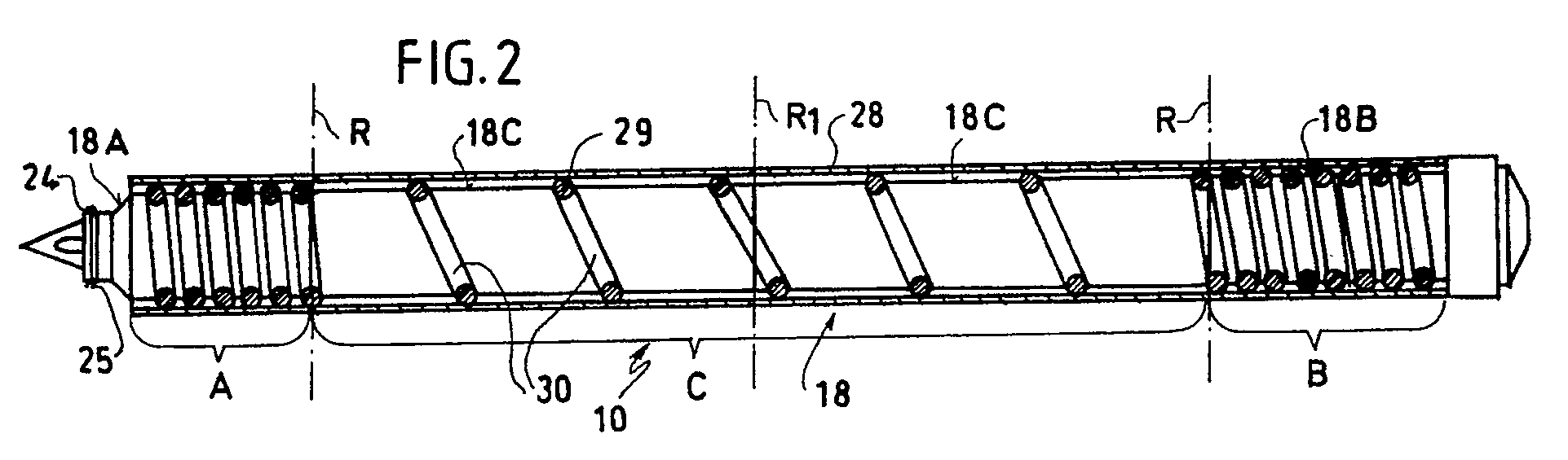
Description
Die Erfindung betrifft eine beheizte Düse, die entsprechend dem jeweiligen Oberbegriff des Patentanspruchs 1 und des diesem nebengeordneten Patentanspruchs 2 durch offenkundige Vorbenutzung bekanntgeworden ist.The invention relates to a heated nozzle, which has become known by public prior use in accordance with the respective preamble of patent claim 1 and the subordinate patent claim 2.
Derartige beheizte Düsen großer axialer Länge, sogenannte Langdüsen, die durch den erhabenen Bereich einer Form hindurch in die Formhöhlung hineinreichen, werden für verschiedene Fälle eingesetzt. Dies geschieht z.B. dann, wenn der Anspritzpunkt von der Ansichtsfläche des Artikels weg - insbesondere nicht ohne weiteres sichtbar in die Hohlseite eines Artikels hinein - plaziert werden soll.Such heated nozzles of great axial length, so-called long nozzles, which extend through the raised area of a mold into the mold cavity, are used for various cases. This happens e.g. then, when the injection point is to be placed away from the face of the article - in particular not easily visible into the hollow side of an article.
Den bei der Beheizung derartig langer Düsen auftretenden Wärmestau hat man bei der offenkundig vorbenutzten Langdüse durch eine weite Wendelung bzw. große Steigung des Rohrheizkörpers im mittleren Bereich des Düsenkörpers vermieden. Bei er eingangs beschriebenen vorbekannten Langdüse weist der rohrförmige Düsenkörper eine glatte Außenmantelfläche auf, an welcher der schraubenlinienförmig gewendelte Rohrheizkörper linienartig anliegt. Um die Wärmeübertragung vom Rohrheizkörper auf den Düsenkörper zu verbessern, wird der Rohrheizkörper in einer Kokille oder in einer anderen Hohlform mittels Kupfer oder mittels eines geeigneten Sintermetalls mit der Außenmantelfläche des Düsenkörpers wärmeleitend vergossen.The heat build-up that occurs during the heating of such long nozzles has been avoided in the obviously used long nozzle by a wide spiral or a large slope of the tubular heater in the central region of the nozzle body. In the case of the known long nozzle described at the outset, the tubular nozzle body has a smooth outer surface on which the helical tubular heating element rests in a linear manner. In order to improve the heat transfer from the tubular heater to the nozzle body, the tubular heater is in a mold or in another hollow shape by means of copper or by means of a suitable sintered metal in a heat-conducting manner with the outer surface of the nozzle body.
Obwohl keine feste Regel existiert, ist es üblich, beheizte Düsen, die eine Länge von etwa 200 mm überschreiten, als Langdüsen zu bezeichnen.Although there is no hard and fast rule, it is common to refer to heated nozzles that are approximately 200 mm long as long nozzles.
Von einer Kurzdüse mit einem etwa 45 mm langen rohrförmigen Düsenkörper ist es bekannt, relativ dünne Heizdrähte mittels Hartlot in relativ schmale düsenkörperseitige Umfangsnuten einzulegen. Diese Umfangsnuten verlaufen sowohl an der Zuström- als auch an der Abströmseite der Kunststoffschmelze eng gewendelt und im mittleren Bereich der Düsenkörper-Außenmantelfläche weit gewendelt. Die letztbeschriebene beheizte Kurzdüse ist durch einen sechsseitigen Faltprospekt "MOLD MASTERS Compact Master-Shot Serie" der MOLD MASTERS LIMITED 1988 mit dem Druckvermerk G-CMS-9-88 bekanntgeworden.From a short nozzle with an approximately 45 mm long tubular nozzle body, it is known to insert relatively thin heating wires by means of hard solder in relatively narrow circumferential grooves on the nozzle body side. These circumferential grooves run tightly coiled on both the inflow and outflow side of the plastic melt and are coiled in the central region of the outer surface of the nozzle body. The last-described heated short nozzle has become known through a six-page brochure "MOLD MASTERS Compact Master-Shot Series" from MOLD MASTERS LIMITED 1988 with the G-CMS-9-88 stamp.
Von einer anderen beheizten Kurzdüse (DE-OS 30 46 471) ist es bekannt, einen Rohrheizkörper in entsprechend breite und tiefe Umfangsnuten gleichbleibender Steigung des Düsenkörpers satt einzulegen und mittels einer die Anordnung außen umschließenden Stahlhülse in die Nut hinein zu verpressen. Durch diese Maßnahme wird eine verbesserte Wärmeübertragung vom Rohrheizkörper auf den Düsenkörper erreicht.From another heated short nozzle (DE-OS 30 46 471) it is known to insert a tubular heating element in a correspondingly wide and deep circumferential grooves of constant slope of the nozzle body and to press it into the groove by means of a steel sleeve which surrounds the arrangement on the outside. This measure improves heat transfer from the tubular heater to the nozzle body.
Von einer anderen beheizten Kurzdüse (DE-OS 34 31 173) ist es bekannt, einen einstückigen Düsenkörper auf ein den Zentralkanal für die Kunststoffschmelze bildendes Rohr aufzuschieben.From another heated short nozzle (DE-OS 34 31 173) it is known to push a one-piece nozzle body onto a tube forming the central channel for the plastic melt.
Die eingangs beschriebene, durch offenkundige Vorbenutzung bekanntgewordene Langdüse wird wegen ihres aufwendig anzugießenden, den Rohrheizkörper aufnehmenden Kupfer- bzw. Sintermetallmantels als nachteilig empfunden.The long nozzle described at the outset, which has become known through prior public use, is felt to be disadvantageous because of its complex copper or sintered metal jacket which accommodates the tubular heating element.
Den Düsenkörper einer Langdüse zur Aufnahme eines Rohrheizkörpers mit ausgeprägten breiten und tiefen Nuten gleichbleibender Steigung zu versehen (s. DE-OS 30 46 471), wäre mit einem tragbaren Aufwand an Zerspanungsarbeit grundsätzlich möglich, jedoch ergäbe sich hierbei im Betrieb das Problem eines unzulässigen Wärmestaus. Eine derartige breite und tiefe Nut bei einem überlangen Düsenkörper mit zwei endseitig engen Wendelungen und einer weiten Wendelung im mittleren Bereich (vergleichbar der Kurzdüse entsprechend dem vorerwähnten Prospekt "MOLD-MASTERS....") zu versehen, wäre hingegen nur mit einem äußerst großen Fertigungsaufwand zu realisieren. Dieser unvertretbar große Fertigungsaufwand wäre allein durch die unterschiedliche Nutsteigung hervorgerufen, die sich auf gängigen Drehautomaten nur mit großem Zeitaufwand herstellen läßt.Providing the nozzle body of a long nozzle for receiving a tubular heater with pronounced wide and deep grooves of constant pitch (see DE-OS 30 46 471) would in principle be possible with a manageable amount of machining work, but this would result in the problem of an inadmissible heat build-up during operation . To provide such a wide and deep groove for an overlong nozzle body with two narrow turns at the end and a wide turn in the middle area (comparable to the short nozzle according to the above-mentioned brochure "MOLD-MASTERS ....") would only be extremely large Realize manufacturing costs. This unacceptably large production effort would be caused solely by the different groove pitch, which can only be produced with a large expenditure of time on conventional automatic lathes.
Im Bewußtsein dieser zuletzt beschriebenen Nachteile liegt der Erfindung, ausgehend von der eingangs beschriebenen, offenkundig vorbenutzten Langdüse der engeren Gattung, die Aufgabe zugrunde, eine derartige Langdüse rationeller als bisher herstellen und zusätzlich den individuellen Anforderungen des Formenbauers besser anpassen zu können.In the awareness of these disadvantages described last, the invention, starting from the one described above, is obviously prior use Long nozzle of the narrower genre, the task of producing such a long nozzle more efficiently than before and in addition to being able to better adapt to the individual requirements of the mold maker.
Entsprechend der Erfindung wird diese Aufgabe gemäß dem jeweiligen Kennzeichenteil des Patentanspruchs 1 und des diesem nebengeordneten Patentanspruchs 2 gelöst.According to the invention, this object is achieved in accordance with the respective characterizing part of patent claim 1 and patent claim 2 which is ancillary to this.
Hiernach sieht die Erfindung in erster Linie eine Aufteilung des Düsenkörpers in separate Axialabschnitte vor, von denen jeder eine Umfangsnut einheitlicher Steigung trägt. Derartige Körper mit Umfangsnuten einheitlicher Steigung lassen sich im Vergleich zu Körpern mit Umfangsnuten unterschiedlicher Steigung mit einem Bruchteil der Fertigungskosten auf gängigen Drehautomaten herstellen. Ein weiterer Vorteil der Erfindung besteht darin, daß der Düsenkörper nunmehr entsprechend den in der Praxis häufig vorkommenden Längen gewissermaßen baukastenmäßig zusammengesetzt werden kann. Die Trennfugen zwischen den einzelnen Axialabschnitten erstrecken sich zweckmäßig radial. Die Übergangsanschlüsse der Nuten von einem Axialabschnitt zum anderen lassen sich ohne weiteres durch Relativverdrehung der Axialabschnitte gegeneinander fluchtend herstellen.Accordingly, the invention primarily provides for a division of the nozzle body into separate axial sections, each of which carries a circumferential groove of uniform pitch. Such bodies with circumferential grooves of uniform pitch can be produced on conventional automatic lathes in comparison to bodies with circumferential grooves of different pitch with a fraction of the manufacturing costs. Another advantage of the invention is that the nozzle body can now be put together in a modular manner in accordance with the lengths that frequently occur in practice. The joints between the individual axial sections expediently extend radially. The transition connections of the grooves from one axial section to the other can easily be made in alignment with one another by relative rotation of the axial sections.
Grundsätzlich ist es demnach ebenfalls möglich, daß die vom Formenbauer gewünschte Länge durch Axialabschnitte den individuellen Bedürfnissen seiner Werkzeugform angepaßt werden kann.Basically, it is therefore also possible that the length desired by the mold maker can be adapted to the individual needs of his mold by axial sections.
Das den Zentralkanal für die Kunststoffschmelze bildende kreiszylindrische innere Tragrohr kann herstellerseitig als Fixlänge oder aber als Rohr mit Überlänge, gewissermaßen vom "laufenden Meter" abgelängt, geliefert werden. Auch das Tragrohr kann selbstverständlich auf die individuell erforderliche Länge gekürzt werden.The circular cylindrical inner support tube forming the central channel for the plastic melt can be supplied by the manufacturer as a fixed length or as an excess length tube, cut to a certain extent from the "running meter". Of course, the support tube can also be shortened to the individually required length.
Beheizte Düsen, so auch Langdüsen, können sowohl gehäuselos (in diesem Falle bildet die Formplatte selbst das Gehäuse) als auch zusammen mit einem gesonderten Gehäuse verwendet werden.Heated nozzles, including long nozzles, can be used both without a housing (in this case the molding plate itself forms the housing) or together with a separate housing.
Obwohl die Erfindung im Zusammenhang mit einem Gehäuse auch mit einem einteiligen Gehäusemittelteil zur Anwendung gelangen kann, sieht die Erfindung ergänzend vor, das Gehäusemittelteil in mindestens zwei Axial-Gehäuseteile aufzuteilen, so daß auch hier die grundsätzliche Möglichkeit einer Längenanpassung - z.B. in Form unterschiedlich langer oder zusätzlicher Distanzstücke - möglich ist.Although the invention can also be used in connection with a housing with a one-part middle housing part, the invention additionally provides for dividing the middle housing part into at least two axial housing parts, so that here too the basic possibility of length adjustment - e.g. in the form of different lengths or additional spacers - is possible.
Insgesamt ist es der Erfindung gelungen, eine Langdüse aus normalisierten Einzelteilen baukastenmäßig herzustellen.Overall, the invention has succeeded in building a long nozzle from normalized individual parts.
In weiterer Ausgestaltung der Erfindung ist anstelle mindestens eines mit einer weitgewendelten Nut versehenen Axialabschnittes des Düsenkörpers ein außen glatter kreiszylindrischer Axialabschnitt einsetzbar, dessen Außendurchmesser dem Kerndurchmesser eines mit Nuten versehenen Drüsenkörper-Axialabschnittes gleich ist. Dieses Merkmal sieht die Erfindung vor, wenn auf einem mittleren Axialbereich des Düsenkörpers die Wärmeübertragung in gewissen Anwendungsfällen auf ein Minimum herabgesetzt werden soll.In a further embodiment of the invention, instead of at least one axial section of the nozzle body provided with a coiled groove, an externally smooth circular cylindrical axial section can be used, the outer diameter of which is the same as the core diameter of a grooved body axial section. This feature is provided by the invention when, in certain applications, the heat transfer is to be reduced to a minimum on a central axial region of the nozzle body.
In Kombination der Erfindungsmerkmale mit Merkmalen, die durch die DE-OS 30 46 471 an sich bekannt sind, kann es zur Verbesserung der Wärmeübertragung vom Rohrheizkörper auf den Düsenkörper gegebenenfalls zweckmäßig sein, den Rohrheizkörper mittels einer ihn außen umgebenden, mit dem Düsenkörper koaxialen Hülse in radial angepreßter Lage gegen den Düsenkörper zu halten.In combination of the features of the invention with features that are known per se from DE-OS 30 46 471, it may be expedient to improve the heat transfer from the tubular heater to the nozzle body, the tubular heater by means of a surrounding, coaxial with the nozzle body in sleeve hold radially pressed position against the nozzle body.
In den Zeichnungen ist die Erfindung anhand bevorzugter Ausführungsbeispiele näher dargestellt,
es zeigen
- Fig. 1 eine Langdüse mit Gehäuse in Seitenansicht,
- Fig. 2 eine gehäuselose Langdüse in Seitenansicht unter Weglassung elektrischer Anschlußelemente,
- Fig. 3 Einzelbauelemente einer Langdüse gemäß Fig. 2 unter Weglassung eines Rohrheizkörpers und elektrischer Anschlußelemente und
- Fig. 4 einen axialen Teilschnitt durch den vorderen Bereich einer Langdüse in vergrößerter Darstellung etwa gemäß der mit IV bezeichneten Einkreisung in Fig. 1.
show it
- 1 is a long nozzle with housing in side view,
- 2 a housing-free long nozzle in side view with omission of electrical connection elements,
- Fig. 3 individual components of a long nozzle according to FIG. 2 with the omission of a tubular heater and electrical connection elements and
- 4 shows an axial partial section through the front region of a long nozzle in an enlarged representation approximately according to the encirclement designated IV in FIG. 1.
Die in Fig. 1 dargestellte, insgesamt mit 10 bezeichnete, Langdüse weist eine Länge l von etwa 450 mm auf.The long nozzle shown in FIG. 1, designated overall by 10, has a length l of approximately 450 mm.
Von der Langdüse 10 ist in Fig. 1 lediglich ein Gehäuse 11 mit einem Vorderteil 12, einem Mittelteil 13 und einem Hinterteil 14, letzteres mit einer Stromzuführung 15, zu ersehen.From the
Das Mittelteil 13 besteht aus drei separaten Axialgehäuseteilen 13a, 13b, 13c.The
Die einzelnen Gehäuseteile 12, 13a, 13b, 13c und 14 sind auf zweckmäßige Weise axial aneinandergeschlossen, beispielsweise mittels einer in Fig. 4 dargestellten stufenförmigen Fuge F mit Gewindeverbindung G.The
Bezüglich der weiterzuleitenden Kunststoffschmelze ist das trichterförmig eingezogene Gehäusevorderteil 12 abströmseitig mit einer Düsenöffnung 16 versehen, welche in nicht dargestellter Weise an eine artikelbildende Formhöhlung anschließt.With regard to the plastic melt to be forwarded, the
In die Düsenöffnung 16 hinein ragt eine Düsenspitze 17 eines etwa rohrförmigen Düsenkörpers 18, mit welchem die Düsenspitze 17 entweder einteilig ausgebildet (wie dargestellt) oder als gesondertes Teil eingesetzt sein kann.A
Innerhalb des Düsenkörpers 18 ist ein Tragrohr 19 angeordnet, welches einen Zentralkanal 20 zur Fortleitung der nicht dargestellten Kunststoffschmelze umgibt. Aus dem Zentralkanal 20 fließt die Kunststoffschmelze über einen Teilkanal 21 und die Austrittsöffnung 22 jeweils der Düsenspitze 17 in einen etwa teilparabolartig ausgebildeten Düsenvorraum 23 und von dort - wie oben erwähnt - weiter durch die Düsenöffnung 16 in die nicht gezeigte Formhöhlung. Düsenöffnung 16 und Düsenvorraum 23 sind gemäß Fig. 4 Ausbildungen des Vorderteils 12 des Gehäuses 11. Bei einer gehäuselosen Langdüse 10 sind die Bereiche 16 und 23 von der Formplatte des Werkzeugs unmittelbar gebildet.A
Die erwähnten Bauteile der Langdüse 10 bestehen aus geeignetem Werkstoff, insbesondere aus Metall. So besteht das Gehäuse 11 beispielsweise aus Stahl, der Düsenkörper 18 mit Düsenspitze 17 aus Cu oder aus CuBe. Insbesondere wenn CuBe verwendet wird, ist es zweckmäßig, mit der Düsenspitze 17 einstückig-stoffschlüssige ringförmige Dichtlippen 24, 25 vorzusehen, welche unter dem Druck der Kunststoffschmelze elastisch verformbar sind und sich hierdurch entgegen der Fließrichtung x der Kunststoffschmelze nach rückwärts gegen die Innenwandung 26 des Düseninnenraumes 23 - eine Rückdichtung darstellend - anlegen können. Die beiden Dichtlippen 24, 25 sind einem Zentrierbund 27, welcher sich an der ihm gegenüberliegenden und dort kreiszylindrischen Innenfläche 26 anlegt, in Fließrichtung x stromabwärts vorgelagert.The components of the
Aus Fig. 4 ist noch ein axial vorderer Teil einer aus rostfreiem Edelstahl bestehenden Metallhülse 28 zu ersehen, welche dazu dient, den mit Fig. 2 dargestellten Rohrheizkörper 29 in die sich schraubenlinien- bzw. wendelförmig erstreckende Umfangsnut 30 hineingepreßt zu halten.4 shows an axially front part of a
Zwischen der Metallhülse 28 und dem Gehäuse 11 bzw. 13a, 13b, 13c sowie 14 ist ein Luftspalt S als Wärmeisolation vorhanden.An air gap S is present between the
Die Nut 30, welche außenmantelseitig in den insgesamt mit 18 bezeichneten Düsenkörper spangebend eingearbeitet ist, weist im Hinblick auf die Fließrichtung x der Kunststoffschmelze sowohl bei A, benachbart der Abströmseite, als auch bei B, benachbart der Zuströmseite, eine geringe Steigung bzw. eine enge Wendelung auf. Zwischen diesen Steigungsbereichen A und B ist ein Bereich C vorhanden, in welchem der Rohrheizkörper 29 eine vergleichsweise sehr große Steigung bzw. eine sehr weite Wendelung besitzt.The
Der mittlere Steigungsbereich C mit weiträumiger Wendelung dient der Vermeidung eines Wärmestaus bei Beheizung des Düsenkörpers 18 mittels des mit elektrischem Strom zu beschickendem Rohrheizkörpers 29. Der Rohrheizkörper 29 ist übrigens so aufgebaut, wie in der DE-OS 30 46 471 (vgl. insbesondere Fig. 2) gezeigt.The central slope area C with a wide spiral serves to avoid heat build-up when the
Die jeweilige Steigung der Nut 30 und die jeweilige Steigung des Rohrheizkörpers 29 korrespondieren miteinander in den einzelnen Steigungsbereichen A, C und B, zumal der Rohrheizkörper 29 satt in der Nut 30 einliegt bzw. dort mittels der radiales Untermaß aufweisenden Metallhülse 28 eng eingepreßt gehalten ist.The respective pitch of the
Im Übergang von einem Steigungsbereich A zu C bzw. von C zu B ist der Düsenkörper 18 entlang gestrichelt dargestellter radialer Teilungsebenen R unterteilt. Außerdem ist der Düsenkörper 18 in seinem mittleren Bereich entlang einer zusätzlichen radialen Teilungsebene R1 aufgeteilt. Insgesamt besteht also der Düsenkörper 18 entgegen der Strömungsrichtung x stromaufwärts hintereinanderfolgend aus den einzelnen Axialabschnitten 18A, 18C, 18C und 18B.In the transition from a slope area A to C or from C to B, the
Alle Einzelabschnitte 18A-18C weisen eine aus Fig. 3 gestrichelt ersichtliche Zentralbohrung 31 auf. Mittels dieser Zentralbohrung 31 sind die einzelnen Axialabschnitte 18A-18C in der in den Fig. 2 und 3 dargestellten Reihenfolge auf das umfangsglatte Tragrohr 19 "aufgefädelt" bzw. mit relativ enger Passung, z.B. mit der Passung p6, h7, aufgepreßt.All individual sections 18A-18C have a
Die einzelnen Axialabschnitte 18A-18C sind durch Verdrehung derart zueinander umfangszentriert, daß die einzelnen Steigungsbereiche A, C und B der Nut 30 durchgängig miteinander fluchten, so daß eine Aufnahme des Rohrheizkörpers 29 ohne weiteres übergangslos gewährleistet ist.The individual axial sections 18A-18C are circumferentially centered relative to one another in such a way that the individual pitch areas A, C and B of the
Für den Fall, daß auf einem der mittleren Bereiche bei C die Wärmeübertragung vom Rohrheizkörper 29 auf den Düsenkörper 18 weiter herabgesetzt werden soll, kann anstelle eines Düsenkörper-Axialabschnittes 18C ein außen glatter Axialabschnitt 18G eingesetzt werden, welcher ebenfalls über eine Zentralbohrung 31 gleichen Innendurchmessers - wie vordem beschrieben - verfügt. Die Außenmantelfläche des Axialabschnittes 18G würde in einem solchen Falle vom Rohrheizkörper 29 nur linienförmig berührt, zumal der Außendurchmesser DA des Axialabschnittes 18G gleich dem Kerndurchmesser DK eines der Axialabschnitte 18A, 18C oder 18B ist.In the event that the heat transfer from
Im Zusammenhang der vorangegangenen Beschreibung ist vorstellbar, daß sämtliche wesentlichen Bauteile, als da sind die Gehäuseteile 13a, 13b, 13c, die Düsenkörper-Axialabschnitte 18A-18C, das Tragrohr 19 und schließlich die Metallhülse 28, entsprechend dem individuellen Bedarf des Formenbauers gekürzt werden können.In the context of the preceding description it is conceivable that all essential components, as there are the
Claims (4)
Applications Claiming Priority (2)
| Application Number | Priority Date | Filing Date | Title |
|---|---|---|---|
| DE4005437A DE4005437A1 (en) | 1990-02-21 | 1990-02-21 | Injection moulding jet body - has outer spiral groove to hold heater |
| DE4005437 | 1990-02-21 |
Publications (3)
| Publication Number | Publication Date |
|---|---|
| EP0443203A2 true EP0443203A2 (en) | 1991-08-28 |
| EP0443203A3 EP0443203A3 (en) | 1992-03-11 |
| EP0443203B1 EP0443203B1 (en) | 1994-08-31 |
Family
ID=6400650
Family Applications (1)
| Application Number | Title | Priority Date | Filing Date |
|---|---|---|---|
| EP90125622A Expired - Lifetime EP0443203B1 (en) | 1990-02-21 | 1990-12-28 | Heated nozzle, so-called long nozzle for a plastic injection moulding mould |
Country Status (4)
| Country | Link |
|---|---|
| EP (1) | EP0443203B1 (en) |
| AT (1) | ATE110620T1 (en) |
| DE (1) | DE4005437A1 (en) |
| HK (1) | HK51497A (en) |
Cited By (9)
| Publication number | Priority date | Publication date | Assignee | Title |
|---|---|---|---|---|
| EP0742091A1 (en) * | 1995-05-05 | 1996-11-13 | Electra Form, Inc. | Flexible hot manifold assembly for injection moulding machines |
| EP0780209A1 (en) * | 1995-12-18 | 1997-06-25 | Mold-Masters Limited | Injection molding carbide torpedo |
| EP0781640A3 (en) * | 1995-12-23 | 1997-07-09 | EWIKON Heisskanalsysteme GmbH & CO. Kommanditgesellschaft | Heated needle valve nozzle |
| EP1584442A1 (en) * | 2004-04-07 | 2005-10-12 | Mold-Masters Limited | Nozzle having a nozzle body with heated and unheated nozzle body segments |
| EP1584443A1 (en) * | 2004-04-07 | 2005-10-12 | Mold-Masters Limited | Nozzle having a nozzle body with heated and unheated nozzle body segments |
| US7462030B2 (en) | 2004-04-07 | 2008-12-09 | Mold-Masters (2007) Limited | Nozzle having a nozzle body with heated and unheated nozzle body segments |
| US7559760B2 (en) | 2004-04-07 | 2009-07-14 | Mold-Masters (2007) Limited | Modular injection nozzle having a thermal barrier |
| US7703188B2 (en) | 2005-05-19 | 2010-04-27 | Mold-Masters (2007) Limited | Thermal shroud and method of making same |
| USRE41536E1 (en) | 2004-01-06 | 2010-08-17 | Mold-Masters (2007) Limited | Injection molding apparatus having an elongated nozzle incorporating multiple nozzle bodies in tandem |
Families Citing this family (5)
| Publication number | Priority date | Publication date | Assignee | Title |
|---|---|---|---|---|
| DE4119581A1 (en) * | 1991-06-14 | 1992-12-17 | Schaeffler Waelzlager Kg | Low wastage, high output rate mould - has heated core tool with feed bore and with gates along its length to supply more than one set of radially outer sliding mould tools |
| DE4404894C1 (en) * | 1994-02-16 | 1995-01-05 | Dangelmaier Sfr Formbau | Heated nozzle for feeding a polymer melt into the cavity of a plastics injection mould. |
| CA2311829A1 (en) | 2000-06-16 | 2001-12-16 | Jonathon Fischer | Thermally balanced hot runner nozzle |
| CN107618152A (en) * | 2017-02-07 | 2018-01-23 | 宁波三顺机械设备科技有限公司 | Injection machine |
| JP2023107401A (en) * | 2022-01-24 | 2023-08-03 | セイコーエプソン株式会社 | Material discharge device, 3D modeling device, injection molding device |
Family Cites Families (10)
| Publication number | Priority date | Publication date | Assignee | Title |
|---|---|---|---|---|
| DE2821736C2 (en) * | 1978-05-18 | 1986-03-20 | Leo Pont-Saint-Martin Aosta Enrietti | Spray nozzle for the intermittent injection of plastic into molds |
| DE3046771A1 (en) * | 1980-12-12 | 1982-07-15 | Licentia Patent-Verwaltungs-Gmbh, 6000 Frankfurt | Digital=to=analogue converter - resolution being nearly doubled by reducing repetition frequency of shift clock during register shift period |
| DE3337803C2 (en) * | 1983-10-18 | 1986-07-10 | Herbert Dipl.-Ing. 3559 Allendorf Günther | Hot runner system for injection molding devices |
| DE3431173A1 (en) * | 1984-08-24 | 1986-03-06 | SFR-Formenbau Dangelmaier GmbH, 7410 Reutlingen | Hot runner injection nozzle |
| CA1261576A (en) * | 1988-04-13 | 1989-09-26 | Jobst U. Gellert | Injection molding nozzle having multiple thickness heating element and method of manufacture |
| CA1266359A (en) * | 1988-04-13 | 1990-03-06 | Harald H. Schmidt | Injection molding system with nozzles in tandem |
| US4882469A (en) * | 1988-09-28 | 1989-11-21 | Panos Trakas | Internally heated sprue bushing assembly with a unitary bushing casing core element |
| CA2008171C (en) * | 1990-01-19 | 1997-05-20 | Jobst Ulrich Gellert | Method of making a selected size injection molding nozzle |
| DE9002048U1 (en) * | 1990-02-21 | 1990-04-19 | SFR-Formenbau Dangelmaier GmbH, 7410 Reutlingen | Heated nozzle, so-called long nozzle for a plastic injection molding tool |
| NL9000488A (en) * | 1990-03-01 | 1991-10-01 | Eurotool Bv | METHOD FOR MANUFACTURING AN INJECTION NOZZLE FOR USE IN AN INJECTION MOLDING DEVICE |
-
1990
- 1990-02-21 DE DE4005437A patent/DE4005437A1/en active Granted
- 1990-12-28 AT AT90125622T patent/ATE110620T1/en not_active IP Right Cessation
- 1990-12-28 EP EP90125622A patent/EP0443203B1/en not_active Expired - Lifetime
-
1997
- 1997-04-17 HK HK51497A patent/HK51497A/en not_active IP Right Cessation
Cited By (11)
| Publication number | Priority date | Publication date | Assignee | Title |
|---|---|---|---|---|
| EP0742091A1 (en) * | 1995-05-05 | 1996-11-13 | Electra Form, Inc. | Flexible hot manifold assembly for injection moulding machines |
| US5738149A (en) * | 1995-05-05 | 1998-04-14 | Electra Form, Inc. | Conduit for flexible hot manifold assembly for injection molding machines |
| AU696697B2 (en) * | 1995-05-05 | 1998-09-17 | Wentworth Mold Inc. Electra Form Industries Division Precision Mold Division | Flexible hot manifold assembly for injection molding machines |
| EP0780209A1 (en) * | 1995-12-18 | 1997-06-25 | Mold-Masters Limited | Injection molding carbide torpedo |
| EP0781640A3 (en) * | 1995-12-23 | 1997-07-09 | EWIKON Heisskanalsysteme GmbH & CO. Kommanditgesellschaft | Heated needle valve nozzle |
| USRE41536E1 (en) | 2004-01-06 | 2010-08-17 | Mold-Masters (2007) Limited | Injection molding apparatus having an elongated nozzle incorporating multiple nozzle bodies in tandem |
| EP1584442A1 (en) * | 2004-04-07 | 2005-10-12 | Mold-Masters Limited | Nozzle having a nozzle body with heated and unheated nozzle body segments |
| EP1584443A1 (en) * | 2004-04-07 | 2005-10-12 | Mold-Masters Limited | Nozzle having a nozzle body with heated and unheated nozzle body segments |
| US7462030B2 (en) | 2004-04-07 | 2008-12-09 | Mold-Masters (2007) Limited | Nozzle having a nozzle body with heated and unheated nozzle body segments |
| US7559760B2 (en) | 2004-04-07 | 2009-07-14 | Mold-Masters (2007) Limited | Modular injection nozzle having a thermal barrier |
| US7703188B2 (en) | 2005-05-19 | 2010-04-27 | Mold-Masters (2007) Limited | Thermal shroud and method of making same |
Also Published As
| Publication number | Publication date |
|---|---|
| DE4005437A1 (en) | 1991-08-29 |
| DE4005437C2 (en) | 1992-05-21 |
| EP0443203A3 (en) | 1992-03-11 |
| ATE110620T1 (en) | 1994-09-15 |
| EP0443203B1 (en) | 1994-08-31 |
| HK51497A (en) | 1997-04-25 |
Similar Documents
| Publication | Publication Date | Title |
|---|---|---|
| DE3601385C2 (en) | ||
| EP2667819B1 (en) | Dental drill and method for producing same | |
| EP0223909B1 (en) | Extrusion die for manufacturing a drill blank of hard metal or ceramics | |
| EP0443203B1 (en) | Heated nozzle, so-called long nozzle for a plastic injection moulding mould | |
| DE2839552C3 (en) | Nozzle head for the production of plastic granulate | |
| WO2007090777A1 (en) | Mixing element for a static mixer, a static mixer and process for producing such a mixing element | |
| DE4120166A1 (en) | EXTRACTION TOOL FOR PRODUCING A HARD METAL OR CERAMIC BAR WITH TWISTED INTERNAL HOLES | |
| DE20215960U1 (en) | Electric heating cartridge for cylindrical bodies | |
| DE69025207T2 (en) | CALIBRATION TOOL | |
| DE4300971B4 (en) | Injection molding nozzle and method for producing a nozzle body of a spray nozzle | |
| DE3046471A1 (en) | Heated nozzle core for injection moulding machine - has helical heating element laid in groove on outer face of core | |
| DE1527776C3 (en) | Billet pick-up for metal extrusion | |
| DE4127035A1 (en) | HOT CHANNEL NOZZLE | |
| DE1660169A1 (en) | Spinning nozzle and method for producing a spinning channel of a spinning nozzle | |
| DE10024625B4 (en) | Mold nest for plastics processing | |
| WO2005108044A1 (en) | Injection mold | |
| DE19941160A1 (en) | Cylinder for a screw extruder with channels for a temperature control medium | |
| DE9002048U1 (en) | Heated nozzle, so-called long nozzle for a plastic injection molding tool | |
| DE19533231A1 (en) | Hot runner nozzle for plastics injection mould | |
| WO1990011880A1 (en) | An extrusion tool to shape viscous compounds | |
| DE3640620C2 (en) | ||
| EP0153687A2 (en) | Apparatus for making propellant powder in a rod-like shape | |
| DE1628441C3 (en) | Device for casting a cylindrical hollow body, namely a mixing tube for a jet pump | |
| DE3043306A1 (en) | Double screw extruder has bi:metallic insert - composed of two liners and two bars welded or soldered together | |
| DE1911223B2 (en) | INTRODUCTION DEVICE FOR A LIQUID BATH CALIBRATOR |
Legal Events
| Date | Code | Title | Description |
|---|---|---|---|
| PUAI | Public reference made under article 153(3) epc to a published international application that has entered the european phase |
Free format text: ORIGINAL CODE: 0009012 |
|
| AK | Designated contracting states |
Kind code of ref document: A2 Designated state(s): AT BE CH DE DK ES FR GB GR IT LI LU NL SE |
|
| PUAL | Search report despatched |
Free format text: ORIGINAL CODE: 0009013 |
|
| AK | Designated contracting states |
Kind code of ref document: A3 Designated state(s): AT BE CH DE DK ES FR GB GR IT LI LU NL SE |
|
| 17P | Request for examination filed |
Effective date: 19920212 |
|
| 17Q | First examination report despatched |
Effective date: 19931126 |
|
| RBV | Designated contracting states (corrected) |
Designated state(s): AT CH FR GB LI NL SE |
|
| REG | Reference to a national code |
Ref country code: DE Ref legal event code: 8566 |
|
| GRAA | (expected) grant |
Free format text: ORIGINAL CODE: 0009210 |
|
| AK | Designated contracting states |
Kind code of ref document: B1 Designated state(s): AT CH FR GB LI NL SE |
|
| REF | Corresponds to: |
Ref document number: 110620 Country of ref document: AT Date of ref document: 19940915 Kind code of ref document: T |
|
| GBT | Gb: translation of ep patent filed (gb section 77(6)(a)/1977) |
Effective date: 19940909 |
|
| ET | Fr: translation filed | ||
| EAL | Se: european patent in force in sweden |
Ref document number: 90125622.2 |
|
| PLBE | No opposition filed within time limit |
Free format text: ORIGINAL CODE: 0009261 |
|
| STAA | Information on the status of an ep patent application or granted ep patent |
Free format text: STATUS: NO OPPOSITION FILED WITHIN TIME LIMIT |
|
| 26N | No opposition filed | ||
| REG | Reference to a national code |
Ref country code: CH Ref legal event code: PFA Free format text: SFR FORMENBAU DANGELMAIER GMBH TRANSFER- SFR FORMENBAU GMBH |
|
| NLT1 | Nl: modifications of names registered in virtue of documents presented to the patent office pursuant to art. 16 a, paragraph 1 |
Owner name: SFR FORMENBAU GMBH |
|
| REG | Reference to a national code |
Ref country code: FR Ref legal event code: CD Ref country code: FR Ref legal event code: CA |
|
| REG | Reference to a national code |
Ref country code: GB Ref legal event code: IF02 |
|
| PGFP | Annual fee paid to national office [announced via postgrant information from national office to epo] |
Ref country code: AT Payment date: 20031215 Year of fee payment: 14 |
|
| PGFP | Annual fee paid to national office [announced via postgrant information from national office to epo] |
Ref country code: GB Payment date: 20031218 Year of fee payment: 14 |
|
| PGFP | Annual fee paid to national office [announced via postgrant information from national office to epo] |
Ref country code: FR Payment date: 20031224 Year of fee payment: 14 |
|
| PGFP | Annual fee paid to national office [announced via postgrant information from national office to epo] |
Ref country code: SE Payment date: 20031230 Year of fee payment: 14 |
|
| PGFP | Annual fee paid to national office [announced via postgrant information from national office to epo] |
Ref country code: NL Payment date: 20031231 Year of fee payment: 14 |
|
| PG25 | Lapsed in a contracting state [announced via postgrant information from national office to epo] |
Ref country code: GB Free format text: LAPSE BECAUSE OF NON-PAYMENT OF DUE FEES Effective date: 20041228 Ref country code: AT Free format text: LAPSE BECAUSE OF NON-PAYMENT OF DUE FEES Effective date: 20041228 |
|
| PG25 | Lapsed in a contracting state [announced via postgrant information from national office to epo] |
Ref country code: SE Free format text: LAPSE BECAUSE OF NON-PAYMENT OF DUE FEES Effective date: 20041229 |
|
| PG25 | Lapsed in a contracting state [announced via postgrant information from national office to epo] |
Ref country code: NL Free format text: LAPSE BECAUSE OF NON-PAYMENT OF DUE FEES Effective date: 20050701 |
|
| EUG | Se: european patent has lapsed | ||
| GBPC | Gb: european patent ceased through non-payment of renewal fee |
Effective date: 20041228 |
|
| PG25 | Lapsed in a contracting state [announced via postgrant information from national office to epo] |
Ref country code: FR Free format text: LAPSE BECAUSE OF NON-PAYMENT OF DUE FEES Effective date: 20050831 |
|
| NLV4 | Nl: lapsed or anulled due to non-payment of the annual fee |
Effective date: 20050701 |
|
| REG | Reference to a national code |
Ref country code: FR Ref legal event code: ST |
|
| PGFP | Annual fee paid to national office [announced via postgrant information from national office to epo] |
Ref country code: CH Payment date: 20070111 Year of fee payment: 17 |
|
| REG | Reference to a national code |
Ref country code: CH Ref legal event code: PL |
|
| PG25 | Lapsed in a contracting state [announced via postgrant information from national office to epo] |
Ref country code: LI Free format text: LAPSE BECAUSE OF NON-PAYMENT OF DUE FEES Effective date: 20071231 Ref country code: CH Free format text: LAPSE BECAUSE OF NON-PAYMENT OF DUE FEES Effective date: 20071231 |