EP0443205A1 - Grillage de tamis pour l'enlèvement de matières solides de liquides en écoulement - Google Patents
Grillage de tamis pour l'enlèvement de matières solides de liquides en écoulement Download PDFInfo
- Publication number
- EP0443205A1 EP0443205A1 EP90125715A EP90125715A EP0443205A1 EP 0443205 A1 EP0443205 A1 EP 0443205A1 EP 90125715 A EP90125715 A EP 90125715A EP 90125715 A EP90125715 A EP 90125715A EP 0443205 A1 EP0443205 A1 EP 0443205A1
- Authority
- EP
- European Patent Office
- Prior art keywords
- bars
- movable
- levers
- skids
- grid
- Prior art date
- Legal status (The legal status is an assumption and is not a legal conclusion. Google has not performed a legal analysis and makes no representation as to the accuracy of the status listed.)
- Granted
Links
Images


Classifications
-
- E—FIXED CONSTRUCTIONS
- E02—HYDRAULIC ENGINEERING; FOUNDATIONS; SOIL SHIFTING
- E02B—HYDRAULIC ENGINEERING
- E02B8/00—Details of barrages or weirs ; Energy dissipating devices carried by lock or dry-dock gates
- E02B8/02—Sediment base gates; Sand sluices; Structures for retaining arresting waterborne material
- E02B8/023—Arresting devices for waterborne materials
- E02B8/026—Cleaning devices
Definitions
- the invention relates to a sieve screen for the removal of solid components from flowing liquids, in particular wastewater, consisting of a fixed grid arranged in a supporting frame with an inclination in the direction of flow and a grid movable by external force, the bars of which engage between the bars of the fixed grid and both in the longitudinal direction of the bar and can also be moved with a component perpendicular to the plane of the stationary grid.
- the movable grating is guided by rollers arranged in rails on its two longitudinal sides.
- the guide rails are arranged one above the other in two levels and are connected by switches at their front ends in the direction of the elevator.
- the driving force is generated hydraulically or pneumatically.
- the rollers are guided through a switch to the guide rail running at a higher level.
- the rollers move to the end of the rail and there suddenly fall down onto the guide rail of the lower level.
- the weight of the grating places considerable strain on the material. For the same reason, hitting the rollers on the lower rails is associated with a large noise emission. Since the switch and the lower guide rail are within the liquid flow, coarse materials carried can block the switch.
- the rollers of the grating are pulled against the blocked switch by the hydraulic or pneumatic drive. The tilting of the movable grille caused by this leads to mechanical faults and damage.
- the movable rods are combined into a package and can be driven by a mechanism in such a way that the rods in a movement suitable for collecting and conveying to be brought.
- each point describes a closed curved path, which naturally contains at least one vertical component.
- the movable grid package with its entire weight is suspended in the upper area on eccentric discs.
- the eccentric discs are connected in pairs with chains and are driven together by a motor. There is no lateral guidance and support of the movable grille.
- the arrangement of the eccentric drive in the upper part of the movable grille and its lack of guidance and support over the entire length leads to a grille movement that is not evenly distributed over the entire grille length.
- the transport movements of the movable grille depend only on the size of the eccentric discs and are very limited.
- the drive device also requires considerable design effort.
- the trolley moves back and forth in the flow direction of the wastewater to be cleaned.
- the movable grid is guided on lateral guide ellipses, so that an approximately elliptical movement of the movable grid part can be achieved in connection with the adjusting movement of the hydraulic piston and the movement of the trolley.
- the drive construction is technically very complex and naturally prone to malfunctions for this reason.
- the invention is based on the object of creating a sieve screen according to the generic term mentioned above, which is characterized by a simple construction, a trouble-free and low-noise running of the movable grille.
- the invention as a solution to this problem is characterized from that the movable grille is supported on each longitudinal side via levers on skids and these are mounted in guide profiles of the supporting structure, the levers being pivotable about their connecting axes with the skids by an electric drive.
- the construction according to the invention is largely insensitive to mechanical disturbances. Experience has shown that coarse matter is washed away as a result of increased water supply, and the guideways cannot become blocked, since the skids are able to push the coarse matter back.
- the mechanical structure of the guide arrangement with the lever construction for transmitting the driving forces is simple. The movement of the movable grille is quiet. There is no sudden mechanical stress.
- an electric geared motor as an actuator, which reaches the force-side ends of all the angle levers via rod-shaped parallel guide rods.
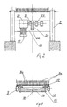
- the embodiment according to FIG. 1 shows a sieve screen 1, which is supported with vertical posts 2 of a supporting structure on the upper edges 3 of a sewer and extends with its lower ends down to the channel bottom 4.
- the sieve screen consists of a fixed grating 5 made of parallel grating bars 5a, which are held together in a packet by means of rod-shaped transverse anchors.
- the cross anchors 6 pass through downward-facing tabs 7, so that it is possible to grasp a movable grating 8 made of rods 8a.
- the individual lattice bars 5a have intermediate distances in which the lattice bars 8a of the movable lattice 8 can engage.
- the movable grid is on the long sides with the help of block-shaped skids 9 in profiles 10 with a U-shaped cross section guided.
- the lattice bars 8a of the movable lattice are also provided with lugs 11 pointing downwards and connected to one another by a bar 12 which extends transversely through the lugs.
- the movable grille is supported on the skids 9 by levers 13.
- Tabs 14 are arranged on the cross bar 12 holding the movable bars together.
- the levers 13 attach to them with their load-side ends.
- the levers in the form of triangles have two arms, since their connection points 15 with the skids 9 lie in the area of the angle.
- the force-side ends of the levers 13 are connected to one another by transverse rods 16 and by a central rod 18 running in the longitudinal direction of the grating, so that this results in parallel guidance.
- the levers 13 can be pivoted with their ends on the load side about the axes 17.
- the drive motor 19 is arranged at the upper end of the grid.
- the output shaft of the reduction gear 20 is connected to one of the crankshaft journals 21.
- a connecting rod 23 extends between the crank pin 22 and the connecting rod 16 of the upper lever 13.
- the crank webs are designated by 24.
- the entire crank mechanism with the geared motor is fastened to a support plate 25 which extends transversely between the supports 2.
- the power transmission arrangement of the embodiment according to FIGS. 1 to 3 enable the use of the motor, the direction of movement of which is uniform.
- the screen rake is shown in its starting position. It rests on the channel floor 4 with its grid 5 that is stationary during use and can be pivoted up and out of the channel around the pivot pin 27 as needed, for example during maintenance work. Solid material carried in the wastewater collects on the front edges of the grids 5 and 8 in the flow direction.
- the bars of the movable grid 8 have the task of moving to the fixed one To transport bars of solid components that are depositing bars upwards. For this reason, the motor 19 is started up in regularly recurring periods, that is to say periodically.
- the crossbar 16 moves towards the engine via the connecting rod 23. As a result, the angle levers are also pivoted towards the motor.
- the movable bars 8a dip down into the gaps between the fixed bars and thereby deposit the material carried on the latter.
- the skids 9 are pushed back into their lower position.
- the movable lattice bars once again reach their lower starting position according to FIG. 1.
- the motor switches off in order to start operation again with the direction of rotation unchanged after a predetermined rest phase. In this way, the solid constituents collecting on the screen, carried along by the wastewater, are gradually led up to the end of the stationary screen 5, from where they can fall into a collecting channel, not shown, for further removal.
- the connecting rod 18 for the lever 13 can be omitted, of which the lower then too simple, articulated between the skids and the movable lattice bars articulated one-armed levers shrink. This simplifies the construction of the parallel guide.
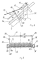
- the sieve screen again consists of the fixed grid 5 with its bars 5a and the movable grid 8 with its bars 8a.
- the movable grille is supported on the skids 9 by levers 30.
- the cross bar 12 holding the movable bars together is guided through tabs 11.
- the rod With its two lateral ends 28, 29, the rod rotatably engages in the angle levers 30 attached to both sides of the sieve rake.
- the angle levers 30 are connected to one another by longitudinal rods 35 and 36 and a transverse rod 37 in such a way that they form a parallel guide.
- the crossbar 37 carries a threaded bush 38 for receiving a threaded spindle 40, which connects the parallel guide to an electric drive motor 41.
- a universal joint 42 enables the inclination of the threaded spindle to be changed during operation.
- the bars 8a are provided with notches 25 in order to achieve better catchability and to prevent the detected solid components from slipping back during the upward transport.
- the screen rake can be pivoted about an axis of rotation 43 on the lateral supports of the supporting structure 2. It rests on the channel floor 4 with its grid 5 that is stationary during use and, if necessary, is pivoted upwards out of the channel around the pivot pin 43, for example during maintenance work. Solid material carried in the wastewater collects on the front edges in the direction of flow. Since the bars of the movable grid 8 have the task of transporting the solid components that are deposited on the fixed bars upwards, it becomes regularly recurring Periods, i.e. periodically, the drive motor 41 is put into operation. Via the threaded spindle 40, which is first turned clockwise, the cross bar 37 of the parallel guide moves towards the motor.
- the angle levers are also pivoted in the direction of the gear motor. They rotate about the pivot axis 32 and thereby lift the movable bars 8a, which at the same time experience a component of movement in the longitudinal direction upwards. As soon as the bars 8a go beyond the level of the stationary bars, they lift the accumulated solid components from the stationary bars and carry the solids up with them until they dip again between the stationary bars and deposit the transported material on their upper edges. During the upward movement, the skids 9 execute a sliding movement within the guide profiles 10.
- the upper end position of the movable lattice bars 8a is illustrated schematically with FIG. 5. When this position is reached, the drive motor switches off and then starts operating again in the opposite direction of rotation.
- the angle levers 30 are pivoted back again.
- the movable bars 8a dip down into the spaces between the fixed bars and thereby deposit the material carried on the latter. This position is illustrated in FIG. 7a.
- the skids 9 are retracted into their lower position.
- the movable lattice bars once again reach their lower starting position according to FIG. 4.
- the drive motor switches off in order to start operation again in a clockwise direction after a predetermined rest phase. In this way, the solid constituents collected on the screen, carried by waste water, are gradually carried up to the end of the stationary screen grid 5, from where they can fall into a collecting trough, not shown, for further removal.
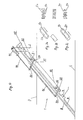
- FIGS. 8 to 11 shows a screen rake 101 which is supported by vertical posts 102 of a supporting structure on the upper edges 103 of a sewer and extends with its lower end down to the channel bottom 104.
- the sieve screen consists of a fixed grating 105 made of parallel grating bars 105a (see FIG. 9), which are held together in a packet by means of rod-shaped transverse anchors 106.
- the cross anchors 106 pass through tabs 107 pointing downward, so that a movable grating 108 made of rods 108a is possible (see FIG. 9).
- the individual lattice bars 105a of the fixed lattice 105 have intermediate distances in which the lattice bars 108a of the movable lattice 108 can engage.
- the bars 105a and 108a are provided with serrations 125.
- the movable grid is guided on the long sides by means of long skids in guide profiles 110 with a U-shaped cross section.
- the fixed grid 105 is fixedly connected to the guide profile 110 at several points by the tabs 107.
- the lattice bars 108a of the movable lattice are also provided with tabs 111 pointing downwards and connected to one another by round bars 112 extending transversely through the tabs.
- the lateral ends 112a are rotatably supported in the levers 113a and 113b.
- the levers 113a and 113b are rotatably supported at their opposite ends via pins 115 on the skids.
- the levers 113b are also connected to the connecting rod 123 via the round rods 112.
- the connecting rod transmits the circular movement of the crank arm 124 as a longitudinal movement to the skids 109.
- the crank arm is moved by a corresponding reduction gear with an electric drive 119.
- the levers 113b are designed as angle levers, the ends of which on the slide runners can be supported against two stops in the form of tabs 145a and 145b.
- the tabs are rigidly attached to the skid 109.
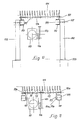
- the rotational movement is transmitted to the rotatable lever 113b via the connecting rod 123.
- the levers 113b and in parallel the levers 113a rotate with an angular movement about the pivot points 115. This angular movement lifts the movable rods 108a out of the spaces between the fixed rods 105a.
- the lever parts 144 on the slide runners lie against the fixed tabs 145a. The angular movement of the levers is thereby ended and the continuing rotational movement of the crank arm 124 is now transmitted as a longitudinal movement via the connecting rod 123 to the skids 109.
- the lattice bars of the movable lattice 108 have the task of transporting the solid components which settle on the fixed lattice bars 105a upwards. For this reason, the electric drive of the crank arm 124 is started up in periodically recurring periods — that is, periodically — as a function of an external control signal.
- the crank arm lifts the movable grill 108 via the connecting rod 123 and the movable levers 113a and 113b.
- the solid components accumulated on the grating 105 are lifted off the grating 105 and shifted upward in the longitudinal direction by the further movement sequence of the movable grating 108. This means that the accumulated solid components are transported upwards.
- the movable grating 108 is lowered and the solid components that have accumulated are deposited again on the stationary grating 105.
- the lowered, mobile Lattice bars 108a return to the starting position between the fixed lattice bars 105a.
- the accumulated solid components on the grids are transported to the discharge end, from where they fall into a collecting channel, not shown, for further removal.
- the screen breaking shown in FIG. 8 can, if necessary, be pivoted up out of the channel base 104 around the pivot 127 of the fixed support 102, for example for maintenance work.
- the mechanical structure of the guide arrangement with the lever construction for transmitting the driving forces is extremely simple. Impairment or blocking by coarse materials of the lower lever arms 113a lying in the water is not possible, because they only move by a few angular degrees.
- An electric geared motor can be used as the actuator, which reaches the upper pair of levers 113b with its crank arm 124 via the connecting rod 123 for lifting and moving the grille.
- the required movement length for the sufficient stroke of the grille is achieved via the radius of the crank arm.
- the angled upper pair of levers fulfills both the function of raising and lowering the grille and the parallel displacement of the grille in the guideways 110.
Landscapes
- Engineering & Computer Science (AREA)
- General Engineering & Computer Science (AREA)
- Mechanical Engineering (AREA)
- Civil Engineering (AREA)
- Structural Engineering (AREA)
- Filtration Of Liquid (AREA)
- Sewage (AREA)
Applications Claiming Priority (2)
| Application Number | Priority Date | Filing Date | Title |
|---|---|---|---|
| DE4001859 | 1990-01-23 | ||
| DE4001859A DE4001859C2 (de) | 1990-01-23 | 1990-01-23 | Siebrechen zur Entnahme von festen Bestandteilen aus strömenden Flüssigkeiten |
Publications (2)
| Publication Number | Publication Date |
|---|---|
| EP0443205A1 true EP0443205A1 (fr) | 1991-08-28 |
| EP0443205B1 EP0443205B1 (fr) | 1992-07-15 |
Family
ID=6398590
Family Applications (1)
| Application Number | Title | Priority Date | Filing Date |
|---|---|---|---|
| EP90125715A Expired - Lifetime EP0443205B1 (fr) | 1990-01-23 | 1990-12-28 | Grillage de tamis pour l'enlèvement de matières solides de liquides en écoulement |
Country Status (4)
| Country | Link |
|---|---|
| US (1) | US5098561A (fr) |
| EP (1) | EP0443205B1 (fr) |
| CA (1) | CA2034250A1 (fr) |
| DE (1) | DE4001859C2 (fr) |
Cited By (2)
| Publication number | Priority date | Publication date | Assignee | Title |
|---|---|---|---|---|
| EP0564870A1 (fr) * | 1992-04-07 | 1993-10-13 | Hans-Georg Huber | Dispositif pour extraire des déchets d'un liquide avec une surface perméable cylindrique |
| CN105174323A (zh) * | 2015-09-11 | 2015-12-23 | 大连诚高科技股份有限公司 | 一种污水处理格栅排污装置 |
Families Citing this family (24)
| Publication number | Priority date | Publication date | Assignee | Title |
|---|---|---|---|---|
| SE9101663L (sv) * | 1991-05-29 | 1992-11-30 | Mellegard Va Maskiner Ab | Anordning vid renstrappa |
| US5552044A (en) * | 1991-07-15 | 1996-09-03 | Abel; Gunther | Apparatus for separating solid material and liquid |
| JPH0710440B2 (ja) * | 1992-02-21 | 1995-02-08 | アムコン株式会社 | 固液分離装置 |
| SE500019C2 (sv) * | 1993-02-08 | 1994-03-21 | Lars Hedman | Uppfordringsanordning för partiklar som bärs av strömmande vatten |
| US5534140A (en) * | 1994-03-17 | 1996-07-09 | Envirex, Inc. | Bar screen having compound fine screen bar rack |
| US6010013A (en) * | 1997-02-03 | 2000-01-04 | Meurer Industries, Inc. | Universal method of and apparatus for screening debris |
| DE19719371A1 (de) * | 1997-05-07 | 1998-11-12 | Egner Umwelttech Gmbh | Vorrichtung zur maschinellen Feststoffseparation aus Flüssigkeiten |
| DE19900817B4 (de) | 1999-01-12 | 2004-04-15 | Hans Huber Ag Maschinen- Und Anlagenbau | Vorrichtung zum Abscheiden und Herausfördern von Abscheidegut aus einer strömenden Flüssigkeit, insbesondere Abwasser |
| RU2144515C1 (ru) * | 1999-03-11 | 2000-01-20 | Общество с ограниченной ответственностью "Экотон" | Сорозадерживающее устройство |
| DE19920074C2 (de) | 1999-05-03 | 2003-12-18 | Hans Huber Ag Masch & Anlagenb | Vorrichtung zum Abscheiden und Herausfördern von Abscheidegut aus einer strömenden Flüssigkeit |
| CN1228515C (zh) * | 2000-12-05 | 2005-11-23 | 汉斯休柏股份公司机器与设备公司 | 从流动液体沉淀及运走沉淀物的设备 |
| US6669854B1 (en) * | 2002-01-22 | 2003-12-30 | Hydro-Dyne Engineering, Inc. | Stepping screen assembly hydraulically driven |
| SE0401062L (sv) * | 2004-04-26 | 2005-02-08 | Mellegaard & Naij Ab | Bottentätning |
| US7815811B1 (en) | 2005-06-03 | 2010-10-19 | Hydro Component Systems, Llc | Trash rake system for clearing intake racks and the like |
| US7919003B2 (en) | 2005-07-19 | 2011-04-05 | Hydro Component Systems, Llc | Protective sleeve for intake rack bars |
| US7416658B2 (en) * | 2006-04-21 | 2008-08-26 | Sung Hur | Elliptical motion drive device for a step screen |
| US9539528B2 (en) | 2011-07-18 | 2017-01-10 | Hydro Component Systems, Llc | Rack and pinion drive for trash rake |
| US10226721B2 (en) | 2016-01-05 | 2019-03-12 | Hydro Component Systems, Llc | Trash rake system with articulated rake head assembly |
| US20180036661A1 (en) * | 2016-08-05 | 2018-02-08 | Patrick M. Anthony | System and Method of Filtering Fibrous and Sheet Segment Materials from Waste Liquid |
| CN107916712B (zh) * | 2017-12-13 | 2024-07-09 | 水利部杭州机械设计研究所 | 旋流截流装置 |
| CN108479159A (zh) * | 2018-06-04 | 2018-09-04 | 安尼康(福建)环保设备有限公司 | 一种叠片式扭摆过滤体及其过滤器 |
| CN111042286B (zh) * | 2019-12-27 | 2024-08-30 | 浙江省水利水电勘测设计院有限责任公司 | 一种排涝工程进水口隐藏式自动升降拦污检修系统 |
| US11633680B2 (en) * | 2020-07-23 | 2023-04-25 | Parkson Corporation | Bar screen filter apparatus and method |
| CN112376680B (zh) * | 2020-10-30 | 2022-05-31 | 陕西黄河规划设计研究有限公司 | 一种用于煤矿地质工程防治水土流失的水土分离装置 |
Citations (5)
| Publication number | Priority date | Publication date | Assignee | Title |
|---|---|---|---|---|
| US1698387A (en) * | 1927-04-02 | 1929-01-08 | Ernest L Broome | Clearing device for water racks |
| US1773576A (en) * | 1926-03-16 | 1930-08-19 | Dorr Co | Bar screen |
| US2170569A (en) * | 1936-03-17 | 1939-08-22 | Montgomery John Arthur | Cutting screen for sewage |
| WO1986007106A1 (fr) * | 1985-05-24 | 1986-12-04 | Hydropress Wallander & Co. Ab | Dispositif pour collecter et decharger des particules solides transportees par de l'eau courante |
| US4853116A (en) * | 1982-07-05 | 1989-08-01 | Hydropress Wallander & Co. | Device for collecting and discharging solid matter |
Family Cites Families (12)
| Publication number | Priority date | Publication date | Assignee | Title |
|---|---|---|---|---|
| US2899062A (en) * | 1959-08-11 | Drive for water intake screens | ||
| DE308042C (fr) * | ||||
| US1751422A (en) * | 1928-09-10 | 1930-03-18 | Charles R Reid | Apparatus for removing water-borne material from raceways and the like |
| US1751421A (en) * | 1928-09-10 | 1930-03-18 | Charles R Reid | Apparatus for removing water-borne material from raceways and the like |
| DE595878C (de) * | 1932-07-05 | 1934-04-23 | Dingler Sche Maschinenfabrik A | Rechenreiniger mit einer auf seitlichen Laufwagen schwenkbar gelagerten Reinigungsharke |
| DE654434C (de) * | 1935-06-28 | 1937-12-23 | Union Handels Akt Ges Bisher S | Rechenreiniger mit ausschwenkbarer, an einem zweiachsigen Laufwagen angeordneter Reinigungsharke |
| DE829730C (de) * | 1949-07-18 | 1952-01-28 | Elio Rampon | Selbstreinigender Rechen fuer Wasserkanaele |
| US2792929A (en) * | 1955-05-17 | 1957-05-21 | Genevieve I Magnuson | Shuffle feed structure |
| DE2214385A1 (de) * | 1972-03-24 | 1973-10-04 | Metallgesellschaft Ag | Reiniger fuer wasserrechen |
| SU864660A1 (ru) * | 1980-07-15 | 1987-08-15 | Центральное Проектно-Конструкторское И Технологическое Бюро "Главсантехпрома" | Механизм выдачи стержней |
| SE436416B (sv) * | 1982-07-05 | 1984-12-10 | Wallander Hydropress Co Ab | Anordning for uppsamling och uppfordring av i avloppsvatten burna, fasta partiklar |
| SE461284B (sv) * | 1988-06-10 | 1990-01-29 | Wallander Hydropress Co Ab | Anordning vid rensgaller |
-
1990
- 1990-01-23 DE DE4001859A patent/DE4001859C2/de not_active Expired - Lifetime
- 1990-12-28 EP EP90125715A patent/EP0443205B1/fr not_active Expired - Lifetime
-
1991
- 1991-01-16 CA CA002034250A patent/CA2034250A1/fr not_active Abandoned
- 1991-01-23 US US07/644,836 patent/US5098561A/en not_active Expired - Lifetime
Patent Citations (5)
| Publication number | Priority date | Publication date | Assignee | Title |
|---|---|---|---|---|
| US1773576A (en) * | 1926-03-16 | 1930-08-19 | Dorr Co | Bar screen |
| US1698387A (en) * | 1927-04-02 | 1929-01-08 | Ernest L Broome | Clearing device for water racks |
| US2170569A (en) * | 1936-03-17 | 1939-08-22 | Montgomery John Arthur | Cutting screen for sewage |
| US4853116A (en) * | 1982-07-05 | 1989-08-01 | Hydropress Wallander & Co. | Device for collecting and discharging solid matter |
| WO1986007106A1 (fr) * | 1985-05-24 | 1986-12-04 | Hydropress Wallander & Co. Ab | Dispositif pour collecter et decharger des particules solides transportees par de l'eau courante |
Cited By (2)
| Publication number | Priority date | Publication date | Assignee | Title |
|---|---|---|---|---|
| EP0564870A1 (fr) * | 1992-04-07 | 1993-10-13 | Hans-Georg Huber | Dispositif pour extraire des déchets d'un liquide avec une surface perméable cylindrique |
| CN105174323A (zh) * | 2015-09-11 | 2015-12-23 | 大连诚高科技股份有限公司 | 一种污水处理格栅排污装置 |
Also Published As
| Publication number | Publication date |
|---|---|
| US5098561A (en) | 1992-03-24 |
| EP0443205B1 (fr) | 1992-07-15 |
| DE4001859A1 (de) | 1991-07-25 |
| CA2034250A1 (fr) | 1991-07-24 |
| DE4001859C2 (de) | 1996-08-29 |
Similar Documents
| Publication | Publication Date | Title |
|---|---|---|
| EP0443205B1 (fr) | Grillage de tamis pour l'enlèvement de matières solides de liquides en écoulement | |
| DE2151439C2 (de) | Endlosförderanlage für Pakete | |
| DE60303597T2 (de) | Kupplungsvorrichtung in einem hängefördersystem | |
| DE1759053A1 (de) | Reinigungsvorrichtung fuer Faenge wie Siebe,Fangrechen,Abscheidegitter usw. | |
| DE2121776A1 (de) | Automatisch aus und einfahrbare Trennwand oder Tür mit mehreren in einer Ebene aneinander anschließenden Trenn wand oder Turtafeln | |
| DE2343182A1 (de) | Raeumeinrichtung fuer klaer- und abwasseranlagen | |
| EP0434862B1 (fr) | Dispositif de soulèvement, notamment pour convoyeurs | |
| EP0611726B1 (fr) | Elévateur pour le montage et le démontage de composants de voitures | |
| DE1481172B2 (de) | Seilschrappervorrichtung zum Beschikken eines Zuteilers für Schüttgüter | |
| DE3829305C2 (fr) | ||
| DE2734119C3 (de) | Rechenreiniger für Stabrechen in wasserbaulichen Anlagen | |
| DE2915341C2 (de) | Rechenreiniger für Stabrechnen | |
| EP3748095A1 (fr) | Installation de degrillage pouvant être montée inclinée dans un canal ouvert | |
| WO1998050638A1 (fr) | Dispositif de filtration etage pour la separation mecanique de solides contenus dans des liquides | |
| DE2608774C3 (de) | Vorrichtung zum Reinigen eines in einem Wasserkanal z.B. Abwasserkanal angeordneten Rechens | |
| DE3134097A1 (de) | Hubbalken | |
| DE2653039C3 (de) | Verteileinrichtung für Stückgüter | |
| DE2554112C2 (de) | Vorrichtung zum Vorschub schwerer Lasten, insbesondere von Brücken oder Brückenplatten | |
| DE3416428C2 (fr) | ||
| EP0087023B1 (fr) | Porteur de charge pour convoyeurs à chaîne trainante circulaire | |
| DE65109C (de) | Treppenfahrstuhl | |
| DE897530C (de) | Foerderanlage, besonders fuer Hochbauten | |
| DE3133450A1 (de) | "magnetische zaehlvorrichtung" | |
| DE2935440A1 (de) | Antrieb fuer eine teleskoptribuene | |
| EP0782821B1 (fr) | Dispositif pour déplacer du fourrage, en particulier du fourrage en blocs, dans la direction d'un cornadis |
Legal Events
| Date | Code | Title | Description |
|---|---|---|---|
| PUAI | Public reference made under article 153(3) epc to a published international application that has entered the european phase |
Free format text: ORIGINAL CODE: 0009012 |
|
| AK | Designated contracting states |
Kind code of ref document: A1 Designated state(s): BE CH DK ES FR GB IT LI NL SE |
|
| 17P | Request for examination filed |
Effective date: 19910910 |
|
| 17Q | First examination report despatched |
Effective date: 19911129 |
|
| GRAA | (expected) grant |
Free format text: ORIGINAL CODE: 0009210 |
|
| AK | Designated contracting states |
Kind code of ref document: B1 Designated state(s): BE CH DK ES FR GB IT LI NL SE |
|
| PG25 | Lapsed in a contracting state [announced via postgrant information from national office to epo] |
Ref country code: IT Free format text: LAPSE BECAUSE OF FAILURE TO SUBMIT A TRANSLATION OF THE DESCRIPTION OR TO PAY THE FEE WITHIN THE PRE;WARNING: LAPSES OF ITALIAN PATENTS WITH EFFECTIVE DATE BEFORE 2007 MAY HAVE OCCURRED AT ANY TIME BEFORE 2007. THE CORRECT EFFECTIVE DATE MAY BE DIFFERENT FROM THE ONE RECORDED.SCRIBED TIME-LIMIT Effective date: 19920715 Ref country code: DK Effective date: 19920715 Ref country code: BE Effective date: 19920715 Ref country code: ES Free format text: THE PATENT HAS BEEN ANNULLED BY A DECISION OF A NATIONAL AUTHORITY Effective date: 19920715 |
|
| PG25 | Lapsed in a contracting state [announced via postgrant information from national office to epo] |
Ref country code: SE Effective date: 19920722 |
|
| ET | Fr: translation filed | ||
| GBT | Gb: translation of ep patent filed (gb section 77(6)(a)/1977) | ||
| PG25 | Lapsed in a contracting state [announced via postgrant information from national office to epo] |
Ref country code: CH Effective date: 19921231 Ref country code: LI Effective date: 19921231 |
|
| PLBE | No opposition filed within time limit |
Free format text: ORIGINAL CODE: 0009261 |
|
| STAA | Information on the status of an ep patent application or granted ep patent |
Free format text: STATUS: NO OPPOSITION FILED WITHIN TIME LIMIT |
|
| 26N | No opposition filed | ||
| REG | Reference to a national code |
Ref country code: CH Ref legal event code: PL |
|
| PGFP | Annual fee paid to national office [announced via postgrant information from national office to epo] |
Ref country code: NL Payment date: 19931231 Year of fee payment: 4 |
|
| PGFP | Annual fee paid to national office [announced via postgrant information from national office to epo] |
Ref country code: FR Payment date: 19940117 Year of fee payment: 4 |
|
| PG25 | Lapsed in a contracting state [announced via postgrant information from national office to epo] |
Ref country code: GB Effective date: 19941228 |
|
| PG25 | Lapsed in a contracting state [announced via postgrant information from national office to epo] |
Ref country code: NL Effective date: 19950701 |
|
| GBPC | Gb: european patent ceased through non-payment of renewal fee |
Effective date: 19941228 |
|
| PG25 | Lapsed in a contracting state [announced via postgrant information from national office to epo] |
Ref country code: FR Effective date: 19950831 |
|
| NLV4 | Nl: lapsed or anulled due to non-payment of the annual fee |
Effective date: 19950701 |
|
| REG | Reference to a national code |
Ref country code: FR Ref legal event code: ST |