EP0443214A2 - Laying method of members - Google Patents
Laying method of members Download PDFInfo
- Publication number
- EP0443214A2 EP0443214A2 EP90201255A EP90201255A EP0443214A2 EP 0443214 A2 EP0443214 A2 EP 0443214A2 EP 90201255 A EP90201255 A EP 90201255A EP 90201255 A EP90201255 A EP 90201255A EP 0443214 A2 EP0443214 A2 EP 0443214A2
- Authority
- EP
- European Patent Office
- Prior art keywords
- members
- moving direction
- moving
- mounting position
- base member
- Prior art date
- Legal status (The legal status is an assumption and is not a legal conclusion. Google has not performed a legal analysis and makes no representation as to the accuracy of the status listed.)
- Withdrawn
Links
- 238000000034 method Methods 0.000 title claims abstract description 18
- 238000011144 upstream manufacturing Methods 0.000 claims abstract description 8
- 229910000831 Steel Inorganic materials 0.000 description 8
- 239000010959 steel Substances 0.000 description 8
- 238000009434 installation Methods 0.000 description 4
- 238000004519 manufacturing process Methods 0.000 description 3
- 238000006243 chemical reaction Methods 0.000 description 2
- 239000000463 material Substances 0.000 description 2
- 239000004809 Teflon Substances 0.000 description 1
- 229920006362 Teflon® Polymers 0.000 description 1
- 230000001174 ascending effect Effects 0.000 description 1
- 239000011083 cement mortar Substances 0.000 description 1
- 239000000945 filler Substances 0.000 description 1
- 239000012530 fluid Substances 0.000 description 1
- 238000011065 in-situ storage Methods 0.000 description 1
- 239000000203 mixture Substances 0.000 description 1
- 230000035515 penetration Effects 0.000 description 1
Images

Classifications
-
- E—FIXED CONSTRUCTIONS
- E04—BUILDING
- E04B—GENERAL BUILDING CONSTRUCTIONS; WALLS, e.g. PARTITIONS; ROOFS; FLOORS; CEILINGS; INSULATION OR OTHER PROTECTION OF BUILDINGS
- E04B1/00—Constructions in general; Structures which are not restricted either to walls, e.g. partitions, or floors or ceilings or roofs
- E04B1/35—Extraordinary methods of construction, e.g. lift-slab, jack-block
-
- E—FIXED CONSTRUCTIONS
- E04—BUILDING
- E04B—GENERAL BUILDING CONSTRUCTIONS; WALLS, e.g. PARTITIONS; ROOFS; FLOORS; CEILINGS; INSULATION OR OTHER PROTECTION OF BUILDINGS
- E04B1/00—Constructions in general; Structures which are not restricted either to walls, e.g. partitions, or floors or ceilings or roofs
- E04B1/35—Extraordinary methods of construction, e.g. lift-slab, jack-block
- E04B2001/3588—Extraordinary methods of construction, e.g. lift-slab, jack-block using special lifting or handling devices, e.g. gantries, overhead conveying rails
Definitions
- the present invention relates to a method of laying members such as concrete slabs on base members such as steel girders and concrete girders.
- the invention presents a laying method of members comprising: a first step for arranging base members along the moving direction of the members to be laid, a second step for placing the members at the mounting positions at the upstream side of the moving direction of the base members, a third step of moving the members placed at the mounting positions to the downstream side of the moving direction by a predetermined length, and a fourth step of placing other members at the mounting positions after removal of the members, and moving the other members to the downstream side of the moving direction together with the above member, wherein the third step and fourth step are repeated, and plural members are laid on the base members.
- the invention since multiple members are laid by placing the members sequentially at the placing positions at the upstream side of the moving direction of the base members and moving to the downstream side of the moving direction, relatively large occupying space is not needed for laying the members at other place than the placing positions, and since the members are either pushed or pulled at the placing positions to move, even if the member laying length is relatively long, it is not necessary to carry the members up to the laying position, and the job efficiency of laying work may be enhanced.
- multiple members are sequentially placed on base members and moved by pushing, and therefore large working space is not needed for carrying the members up to the laying positions, and the members may be laid efficiently. Furthermore, since multiple members may be moved and conveyed from the placing positions to laying positions over a relatively long length in the case of bridge or tunnel members, it is not necessary to transport the materials over a long length, and the job may be done efficiently. Besides, as wide working space is not needed, other work may be done simultaneously while laying the members, and by making use of the laid members, the working space for the other works may be also maintained. Moreover, this is a repetition of simplified work of placing and pushing the members at placing positions, and the control of the installation is easy. In addition, the members carried up to the laying positions may be directly used as the working space or paths for works, and the convenience is enhanced.
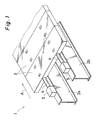
- Fig. 1 is a perspective view showing an embodiment of the invention.
- Multiple parallel steel base members 2a, 2b are installed on a bridge 1, and multiple members, that is, precast slabs 3 are laid on the base members 2a, 2b.
- Such precast slabs 3 are pushed to the downstream side of moving direction A by, for example, a hydraulic jack 4.
- This jack 4 is provided to a steel-made pressure-supporting member 5 in order to receive their reactions so as to push the precast slabs 3.
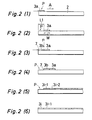
- Fig. 2 is a drawing explaining the procedure for laying the precast slabs 3
- Fig. 3 is a flow chart showing its procedure.
- the first precast slab 3a is put on the mounting position P of the base members 2 as shown in Fig. 2 (1).
- This mounting position P is selected, for example, at the end of the upstream side of moving direction A of the base member 2, and the precast slab 3 is placed by means of crane or the like.
- the precast slab 3a is put on this mounting position P, at step n3, the precast slab 3a is pushed to the downstream side of the moving direction A by the jack 4.
- the moving length L1 of the precast slab 3a is selected to be nearly equal to or slightly larger than the width W along the moving direction A of the precast slab 3a.
- the second precast slab 3b is mounted at step n4 as shown in Fig. 2 (3), and consequently at step n5, as shown in Fig. 2 (4), the end face 7 of the upstream side of moving direction A of the precast slab 3b mounted at step n4 is moved, together with the precast slab 3a pushed towards the downstream side of moving direction A at step n3.
- step n6 it is judged whether the number of precast slab 3 has reached a specified number (i-l), and if not reaching the specified number (i-1), the operation returns to step n4, and a new precast slab is put on the mounting position P, and at step n5 again it is pushed by the jack 4, and the operation from step n4 to step n6 is repeated until reaching the specified number (i-1).
- the operation moves to step n7, where the final precast slab 3i is put on the mounting position P, thereby completing the laying work.
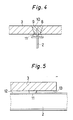
- a stud 8 buried in the base member 2 is put in a penetration hole 9 preliminarily formed in the precast slab, and filler such as cement mortar is charged to fill up and harden, so that the base member 2 and the precast slab 3 are integrally fixed. Fixing of such base member 2 and the precast slab 3 may be effected on each precast slab 3 laid according to the laying method of the invention.
- an intervening piece 11 made of a material relatively small in the friction coefficient, for example, fluororesin (tradename: Teflon) is placed between the upper surface 12 of the base member 2 and the lower surface 13 of the precast slab 3.
- fluororesin tradename: Teflon
- each precast slab 3 can move while sliding smoothly on the upper surface 12 of the base member 2 to the downstream side of the moving direction A, together with the intervening piece 11, so that only a small pushing force is needed for the jack 4. Consequently, the structure of the support pushing member 5 resisting the reaction from the jack 4 may be reduced in size, and the entire structure for moving the precast slab 3 may be hence reduced in size.
- the precast slab 3 is pushed from the work start end side, even if the upper surface 12 of the base member 2 is in an ascending slope going up to the horizontal plane as moving downstream of the moving direction A, the slab 3 will not move reversely to the upstream side of the moving direction A.
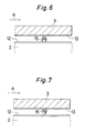
- a roller 14 may be installed in the lower surface 13 of the precast slab 3, as shown in Fig. 6, so as to move the precast slab 3, together with this roller 14, to the downstream side of the moving direction A on the upper surface 12 of the base member 2, or furthermore as shown in Fig. 7 a roller 15 may be installed on the upper surface 12 of the base member 2, and the precast slab 3 may be moved on the roller 15.
- the friction resistance in moving of the precast slab 3 may be reduced, so that the precast slab 3 may be easily moved towards the downstream side of the moving direction A.
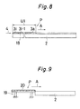
- Fig. 8 is a drawing for explaining the laying method of other embodiment of the invention.
- multiple precast slabs 3a to 3i are put on the base members 2 in the same procedure as in the embodiment shown in Fig. 2 and Fig. 3, and these precast slabs 3a to 3i are tied by using PC steel wires 18 to make up one unit U1, and this entire unit U1 is moved by pushing to the downstream side of the movable direction A by the jack 4.
- the precast slabs 3 can be laid on the base members 2. In this way, it is not necessary to carry the precast slabs 3, PC steel wires 18 and the tightening device over a long length on the bridge 1, and the installation speed may be outstandingly improved.
- the precase slabs 3a to 3i of one unit U1 may be tied by using PC steel wires 18 at a different place than the mounting position P, and may be put on the mounting position P on the base member 2 by using a crane or the like.
- Fig. 9 shows a laying method of a still different embodiment of the invention.
- a fabrication yard 19 is set up by assembling shores with multiple section steels and mounting covering plates. Forms are set up on this fabrication yard 19, and the concrete slabs 20 are manufactured, and are pushed and moved onto the base members 2 by the jack 4. By fabricating such concrete cast in situ slabs 20 on the fabrication yard 19 and repeating the moving work, multiple concrete slabs 20 may be laid on the base member 2.
- forms are assembled on the mounting position P of the base member 2, field-placed concrete slabs 20 are fabricated, the forms are removed, and the slabs 20 are moved to the downstream side of the moving direction A.
- the base members 2 are made of steel, but in other embodiments of the invention, they may be concrete girders, or other members such as walls.
- the precast slabs 3 are moved by pushing to the downstream side of the moving direction A by the jack 4, but it may be also possible to compose so as to move to the downstream side of the moving direction A by installing pulling means at the downstream side of the moving direction A from the mounting position P, for example, a take-up device having a wire rope wound around a reel, and connecting the end of the wire rope to the precast slab 3, unit U1 or concrete slab 20 arranged at the mounting position P.
Landscapes
- Engineering & Computer Science (AREA)
- Architecture (AREA)
- Physics & Mathematics (AREA)
- Electromagnetism (AREA)
- Civil Engineering (AREA)
- Structural Engineering (AREA)
- Bridges Or Land Bridges (AREA)
Abstract
The invention presents a laying method of members comprising: a first step for arranging a base member(2) along a moving direction(A) of the member(3a) to be laid, a second step for placing the member(3a) at the mounting position(P) at the upstream side of the moving direction(A) of the base member(2), a third step of moving the member(3a) placed at the mounting position(A) to the downstream side of the moving direction(A) by a predetermined length(L1), and a fourth step of placing another member(3b) at the mounting position(P) after removal of the member(3a), and moving the another member(3b) to the downstream side of the moving direction(A) together with the above member(3a), wherein the third step and fourth step are repeated, and multiple members(3a-3i) are laid on the base member(2). Thereby, without requiring a large occupying space, the members (3a-3i) may be laid down efficiently. <IMAGE>
Description
- The present invention relates to a method of laying members such as concrete slabs on base members such as steel girders and concrete girders.
- Conventionally, to lay slabs or other members on base members such as steel girders, forms were set up along the base members, and fluid concrete was placed within the forms, being constructed by the so-called in-site concrete placing method.
- In such prior art, where the length of installation area is long, the forms must be delivered to the concrete placing positions extending over a long distance, and the efficiency of installation work is poor, or in a relatively narrow working space such as inside of a tunnel, a relatively large space is occupied by the assembled forms.
- It is hence a primary object of the invention to present a laying method of members capable of laying members efficiently without requiring a large occupying space.
- To achieve the above object, the invention presents a laying method of members comprising:
a first step for arranging base members along the moving direction of the members to be laid,
a second step for placing the members at the mounting positions at the upstream side of the moving direction of the base members,
a third step of moving the members placed at the mounting positions to the downstream side of the moving direction by a predetermined length, and
a fourth step of placing other members at the mounting positions after removal of the members, and moving the other members to the downstream side of the moving direction together with the above member, wherein
the third step and fourth step are repeated, and plural members are laid on the base members. - According to the invention, since multiple members are laid by placing the members sequentially at the placing positions at the upstream side of the moving direction of the base members and moving to the downstream side of the moving direction, relatively large occupying space is not needed for laying the members at other place than the placing positions, and since the members are either pushed or pulled at the placing positions to move, even if the member laying length is relatively long, it is not necessary to carry the members up to the laying position, and the job efficiency of laying work may be enhanced.
- In the invention, multiple members are sequentially placed on base members and moved by pushing, and therefore large working space is not needed for carrying the members up to the laying positions, and the members may be laid efficiently. Furthermore, since multiple members may be moved and conveyed from the placing positions to laying positions over a relatively long length in the case of bridge or tunnel members, it is not necessary to transport the materials over a long length, and the job may be done efficiently. Besides, as wide working space is not needed, other work may be done simultaneously while laying the members, and by making use of the laid members, the working space for the other works may be also maintained. Moreover, this is a repetition of simplified work of placing and pushing the members at placing positions, and the control of the installation is easy. In addition, the members carried up to the laying positions may be directly used as the working space or paths for works, and the convenience is enhanced.
- Other and further objects, features, and advantages of the invention will be more explicit from the following detailed description taken with reference to the drawings wherein:
- Fig. 1 is a perspective view showing a laying method in one of the embodiments of the invention,
- Fig. 2 is a drawing for explaining the procedure of laying
precast slabs 3, - Fig. 3 is a flow chart showing its procedure,
- Fig. 4 is a sectional view showing the composition for fixing
precast slabs 3 and abase member 2, - Fig. 5 is a drawing of an
interface member 11 placed betweenprecast slabs 3 andbase member 2, - Fig. 6 is a side view near a roller 14 in other embodiment of the invention,
- Fig. 7 is a side view near a
roller 15 in a different embodiment of the invention, - Fig. 8 is a drawing for explaining the laying method of another embodiment of the invention, and
- Fig. 9 is a drawing for explaining the laying method of a further different embodiment of the invention.
- Now referring to the drawing, preferred embodiments of the invention are described below.
- Fig. 1 is a perspective view showing an embodiment of the invention. Multiple parallel
steel base members bridge 1, and multiple members, that is,precast slabs 3 are laid on thebase members precast slabs 3 are pushed to the downstream side of moving direction A by, for example, ahydraulic jack 4. Thisjack 4 is provided to a steel-made pressure-supportingmember 5 in order to receive their reactions so as to push theprecast slabs 3. - Fig. 2 is a drawing explaining the procedure for laying the
precast slabs 3, and Fig. 3 is a flow chart showing its procedure. When the job is started at step n1, andbase member 2 are positioned at step n2, and thefirst precast slab 3a is put on the mounting position P of thebase members 2 as shown in Fig. 2 (1). This mounting position P is selected, for example, at the end of the upstream side of moving direction A of thebase member 2, and theprecast slab 3 is placed by means of crane or the like. When thefirst precast slab 3a is put on this mounting position P, at step n3, theprecast slab 3a is pushed to the downstream side of the moving direction A by thejack 4. At this time, the moving length L1 of theprecast slab 3a is selected to be nearly equal to or slightly larger than the width W along the moving direction A of theprecast slab 3a. - Thus, as shown in Fig. 2 (2), at the mounting position P becoming vacant after moving the
precast slab 3a, the secondprecast slab 3b is mounted at step n4 as shown in Fig. 2 (3), and consequently at step n5, as shown in Fig. 2 (4), theend face 7 of the upstream side of moving direction A of theprecast slab 3b mounted at step n4 is moved, together with theprecast slab 3a pushed towards the downstream side of moving direction A at step n3. - At step n6, it is judged whether the number of
precast slab 3 has reached a specified number (i-l), and if not reaching the specified number (i-1), the operation returns to step n4, and a new precast slab is put on the mounting position P, and at step n5 again it is pushed by thejack 4, and the operation from step n4 to step n6 is repeated until reaching the specified number (i-1). Thus, when theprecast slab 3 are laid by the specified number (i-1) as shown in Fig. 2 (5) at step n6, the operation moves to step n7, where thefinal precast slab 3i is put on the mounting position P, thereby completing the laying work. - In the
precast slabs 3 thus laid on thebase members 2, as shown in Fig. 4, astud 8 buried in thebase member 2 is put in apenetration hole 9 preliminarily formed in the precast slab, and filler such as cement mortar is charged to fill up and harden, so that thebase member 2 and theprecast slab 3 are integrally fixed. Fixing ofsuch base member 2 and theprecast slab 3 may be effected on eachprecast slab 3 laid according to the laying method of the invention. When moving theprecast slab 3 on thebase member 2, as shown in Fig. 5, anintervening piece 11 made of a material relatively small in the friction coefficient, for example, fluororesin (tradename: Teflon) is placed between theupper surface 12 of thebase member 2 and thelower surface 13 of theprecast slab 3. As a result, eachprecast slab 3 can move while sliding smoothly on theupper surface 12 of thebase member 2 to the downstream side of the moving direction A, together with theintervening piece 11, so that only a small pushing force is needed for thejack 4. Consequently, the structure of thesupport pushing member 5 resisting the reaction from thejack 4 may be reduced in size, and the entire structure for moving theprecast slab 3 may be hence reduced in size. Besides, since theprecast slab 3 is pushed from the work start end side, even if theupper surface 12 of thebase member 2 is in an ascending slope going up to the horizontal plane as moving downstream of the moving direction A, theslab 3 will not move reversely to the upstream side of the moving direction A. - As other embodiment of the invention relation to Fig. 5, a roller 14 may be installed in the
lower surface 13 of theprecast slab 3, as shown in Fig. 6, so as to move theprecast slab 3, together with this roller 14, to the downstream side of the moving direction A on theupper surface 12 of thebase member 2, or furthermore as shown in Fig. 7 aroller 15 may be installed on theupper surface 12 of thebase member 2, and theprecast slab 3 may be moved on theroller 15. By theserollers 14, 15, also, the friction resistance in moving of theprecast slab 3 may be reduced, so that theprecast slab 3 may be easily moved towards the downstream side of the moving direction A. - Fig. 8 is a drawing for explaining the laying method of other embodiment of the invention. In this embodiment, multiple
precast slabs 3a to 3i are put on thebase members 2 in the same procedure as in the embodiment shown in Fig. 2 and Fig. 3, and theseprecast slabs 3a to 3i are tied by usingPC steel wires 18 to make up one unit U1, and this entire unit U1 is moved by pushing to the downstream side of the movable direction A by thejack 4. Thus, by moving in each unit after bundling multipleprecast slabs 3, theprecast slabs 3 can be laid on thebase members 2. In this way, it is not necessary to carry theprecast slabs 3,PC steel wires 18 and the tightening device over a long length on thebridge 1, and the installation speed may be outstandingly improved. - In a further different embodiment of the invention, in the example shown in Fig. 8, the
precase slabs 3a to 3i of one unit U1 may be tied by usingPC steel wires 18 at a different place than the mounting position P, and may be put on the mounting position P on thebase member 2 by using a crane or the like. - Fig. 9 shows a laying method of a still different embodiment of the invention. At the upstream side of the moving direction A of the
base member 2, afabrication yard 19 is set up by assembling shores with multiple section steels and mounting covering plates. Forms are set up on thisfabrication yard 19, and theconcrete slabs 20 are manufactured, and are pushed and moved onto thebase members 2 by thejack 4. By fabricating such concrete cast in situ slabs 20 on thefabrication yard 19 and repeating the moving work,multiple concrete slabs 20 may be laid on thebase member 2. - In another different embodiment of the invention, forms are assembled on the mounting position P of the
base member 2, field-placedconcrete slabs 20 are fabricated, the forms are removed, and theslabs 20 are moved to the downstream side of the moving direction A. - In the foregoing embodiments, the
base members 2 are made of steel, but in other embodiments of the invention, they may be concrete girders, or other members such as walls. - Besides, in the above embodiments, the
precast slabs 3 are moved by pushing to the downstream side of the moving direction A by thejack 4, but it may be also possible to compose so as to move to the downstream side of the moving direction A by installing pulling means at the downstream side of the moving direction A from the mounting position P, for example, a take-up device having a wire rope wound around a reel, and connecting the end of the wire rope to theprecast slab 3, unit U1 orconcrete slab 20 arranged at the mounting position P. - The invention may be embodied in other specific forms without departing from the spirit or essential characteristics thereof. The present embodiments are therefore to be considered in all respects as illustrative and not restrictive, the scope of the invention being indicated by the appended claims rather than by the foregoing description and all changes which come within the meaning and the range of equivalency of the claims are therefore intended to be embraced therein.
Claims (1)
- A laying method of members comprising:
a first step for arranging a base member(2) along a moving direction(A) of the member(3a) to be laid,
a second step for placing the member(3a) at the mounting position(P) at the upstream side of the moving direction(A) of the base member(2),
a third step of moving the member(3a) placed at the mounting position(A) to the downstream side of the moving direction(A) by a predetermined length(L1), and
a fourth step of placing another member(3b) at the mounting position(P) after removal of the member(3a), and moving the another member(3b) to the downstream side of the moving direction(A) together with the above member(3a), wherein
the third step and fourth step are repeated, and plural members(3a-3i) are laid on the base member(2).
Applications Claiming Priority (2)
| Application Number | Priority Date | Filing Date | Title |
|---|---|---|---|
| JP2040609A JPH03244741A (en) | 1990-02-20 | 1990-02-20 | Method for laying member |
| JP40609/90 | 1990-02-20 |
Publications (2)
| Publication Number | Publication Date |
|---|---|
| EP0443214A2 true EP0443214A2 (en) | 1991-08-28 |
| EP0443214A3 EP0443214A3 (en) | 1993-05-05 |
Family
ID=12585266
Family Applications (1)
| Application Number | Title | Priority Date | Filing Date |
|---|---|---|---|
| EP19900201255 Withdrawn EP0443214A3 (en) | 1990-02-20 | 1990-05-17 | Laying method of members |
Country Status (3)
| Country | Link |
|---|---|
| US (1) | US5090176A (en) |
| EP (1) | EP0443214A3 (en) |
| JP (1) | JPH03244741A (en) |
Cited By (2)
| Publication number | Priority date | Publication date | Assignee | Title |
|---|---|---|---|---|
| CN106379704A (en) * | 2016-11-01 | 2017-02-08 | 山东电力建设第工程公司 | Push-pull translation steering construction system for large equipment |
| CN111058379A (en) * | 2018-10-16 | 2020-04-24 | 武汉思力特种工程机械施工有限公司 | Walking type sliding and pushing construction method for bridge construction |
Families Citing this family (3)
| Publication number | Priority date | Publication date | Assignee | Title |
|---|---|---|---|---|
| US8220095B2 (en) * | 2010-01-29 | 2012-07-17 | Skanska USA Civil Inc. | Highway overpass bridge modification system and method |
| JP5867451B2 (en) * | 2012-06-21 | 2016-02-24 | Jfeスチール株式会社 | Temporary bridge construction method and precast slab used in the construction method |
| CN110656703B (en) * | 2018-06-29 | 2021-06-01 | 上海宝冶集团有限公司 | Multifunctional sliding shoe sliding post-top construction device for non-rail interface |
Family Cites Families (12)
| Publication number | Priority date | Publication date | Assignee | Title |
|---|---|---|---|---|
| NL269923A (en) * | 1961-10-04 | |||
| BE623330A (en) * | 1961-11-07 | |||
| US3570207A (en) * | 1969-07-10 | 1971-03-16 | Pierre Launay | Method of advancing bridging structures made from prestressed concrete |
| US4054014A (en) * | 1972-08-21 | 1977-10-18 | Lely Cornelis V D | Methods of erecting prefabricated buildings and equipment employed in such methods |
| US4006574A (en) * | 1972-09-01 | 1977-02-08 | Lely Cornelis V D | Method of forming a construction of building substructures |
| GB1548897A (en) * | 1976-05-06 | 1979-07-18 | Redpath Dorman Long Ltd | Movement of bridge spans or the like |
| DE3214742A1 (en) * | 1982-04-21 | 1983-10-27 | Werner Dipl.-Ing.(FH) 8300 Altdorf Mengelkamp | Air-cushion method for pushing in bridge superstructures |
| DE3242153A1 (en) * | 1982-11-13 | 1984-05-17 | Polensky & Zöllner GmbH & Co., 6000 Frankfurt | Method for installing a multi-field support framework |
| US4697397A (en) * | 1985-08-10 | 1987-10-06 | Shimizu Construction Co. Ltd. | Trussed girder, roof framing using the trussed girder and method of constructing the roof framing of a building using the trussed girder |
| JPH0718204B2 (en) * | 1986-11-28 | 1995-03-01 | 株式会社オクジュー | Ceiling construction method |
| DE3700938A1 (en) * | 1987-01-15 | 1988-07-28 | Strabag Bau Ag | MANUFACTURING DEVICE FOR MANUFACTURING A LONG STRETCHED CONSTRUCTION |
| DE3701682A1 (en) * | 1987-01-22 | 1988-08-04 | Strabag Bau Ag | METHOD FOR PRODUCING A LONG-STRETCHED CONSTRUCTION |
-
1990
- 1990-02-20 JP JP2040609A patent/JPH03244741A/en active Pending
- 1990-05-16 US US07/524,048 patent/US5090176A/en not_active Expired - Fee Related
- 1990-05-17 EP EP19900201255 patent/EP0443214A3/en not_active Withdrawn
Cited By (2)
| Publication number | Priority date | Publication date | Assignee | Title |
|---|---|---|---|---|
| CN106379704A (en) * | 2016-11-01 | 2017-02-08 | 山东电力建设第工程公司 | Push-pull translation steering construction system for large equipment |
| CN111058379A (en) * | 2018-10-16 | 2020-04-24 | 武汉思力特种工程机械施工有限公司 | Walking type sliding and pushing construction method for bridge construction |
Also Published As
| Publication number | Publication date |
|---|---|
| EP0443214A3 (en) | 1993-05-05 |
| JPH03244741A (en) | 1991-10-31 |
| US5090176A (en) | 1992-02-25 |
Similar Documents
| Publication | Publication Date | Title |
|---|---|---|
| US8065845B1 (en) | Anchorage with tendon sheathing lock and seal | |
| EP1219757B1 (en) | Tendon-receiving duct with longitudinal channels | |
| JPS5869908A (en) | Free tension material, method and apparatus for producing and assembling obliquely tentioned cable of bridge | |
| EP0443214A2 (en) | Laying method of members | |
| CN111088821A (en) | Surface displacement monitoring system and monitoring method for assembled lattice beam | |
| JPH03500637A (en) | Flexible guide rail and its manufacturing method | |
| JP7019660B2 (en) | Installation structure of lightweight lining board | |
| US20050257456A1 (en) | Homes and home construction | |
| CN110878609B (en) | Construction method of unbonded prestressed waffle slab | |
| JP4493245B2 (en) | Suspended floor slab bridge and method for reinforcing suspended floor slab | |
| JP2000329530A (en) | Displacement sensor of displacement measuring device and method of installing the same | |
| EP1242696B1 (en) | Supporting method for hollow-core slabs and end attachment | |
| JP2761983B2 (en) | Laying method of temperature distribution measurement cable | |
| GB2222624A (en) | Drainage channel support system | |
| JPH1162085A (en) | Formation of surface part and panel thereof | |
| KR102393967B1 (en) | Prestressing module and production method thereof | |
| KR20120072446A (en) | Precast segment of the stress ribbon bridge and system/method constructing the stress ribbon bridge by it | |
| JPS6232284B2 (en) | ||
| JP4551279B2 (en) | Floor structure | |
| JPH0874381A (en) | Reinforcement unit and construction method of reinforced concrete building using the unit | |
| JP2004308422A (en) | Prestress introduction method and concrete structure | |
| JP2005083190A (en) | EXTENDED STRUCTURE AND METHOD FOR FORMING THE SAME | |
| HK40037869A (en) | Lapped joint between concrete structures, method for forming the same, and grouting monitor used during grouting | |
| NL1007043C1 (en) | Duplex anchor for tensile cable used to e.g. reinforce soil around dam walls or anchor tall buildings such as transmitter masts | |
| JPH066603U (en) | Bar material for fixing concrete buried objects |
Legal Events
| Date | Code | Title | Description |
|---|---|---|---|
| PUAI | Public reference made under article 153(3) epc to a published international application that has entered the european phase |
Free format text: ORIGINAL CODE: 0009012 |
|
| AK | Designated contracting states |
Kind code of ref document: A2 Designated state(s): BE DE FR GB |
|
| PUAL | Search report despatched |
Free format text: ORIGINAL CODE: 0009013 |
|
| AK | Designated contracting states |
Kind code of ref document: A3 Designated state(s): BE DE FR GB |
|
| STAA | Information on the status of an ep patent application or granted ep patent |
Free format text: STATUS: THE APPLICATION IS DEEMED TO BE WITHDRAWN |
|
| 18D | Application deemed to be withdrawn |
Effective date: 19931201 |