EP0443216A1 - Construction de toit ouvrant à moteur électrique - Google Patents
Construction de toit ouvrant à moteur électrique Download PDFInfo
- Publication number
- EP0443216A1 EP0443216A1 EP90203258A EP90203258A EP0443216A1 EP 0443216 A1 EP0443216 A1 EP 0443216A1 EP 90203258 A EP90203258 A EP 90203258A EP 90203258 A EP90203258 A EP 90203258A EP 0443216 A1 EP0443216 A1 EP 0443216A1
- Authority
- EP
- European Patent Office
- Prior art keywords
- roof construction
- open roof
- reference means
- electric open
- switching
- Prior art date
- Legal status (The legal status is an assumption and is not a legal conclusion. Google has not performed a legal analysis and makes no representation as to the accuracy of the status listed.)
- Granted
Links
- 238000010276 construction Methods 0.000 title claims abstract description 23
- 230000005540 biological transmission Effects 0.000 claims description 13
- 230000003287 optical effect Effects 0.000 claims description 4
- 244000027321 Lychnis chalcedonica Species 0.000 claims description 2
- 230000000903 blocking effect Effects 0.000 description 1
- 238000001514 detection method Methods 0.000 description 1
- 230000000694 effects Effects 0.000 description 1
- 230000002708 enhancing effect Effects 0.000 description 1
- 230000002349 favourable effect Effects 0.000 description 1
- 230000010354 integration Effects 0.000 description 1
- 238000009423 ventilation Methods 0.000 description 1
Images

Classifications
-
- B—PERFORMING OPERATIONS; TRANSPORTING
- B60—VEHICLES IN GENERAL
- B60J—WINDOWS, WINDSCREENS, NON-FIXED ROOFS, DOORS, OR SIMILAR DEVICES FOR VEHICLES; REMOVABLE EXTERNAL PROTECTIVE COVERINGS SPECIALLY ADAPTED FOR VEHICLES
- B60J7/00—Non-fixed roofs; Roofs with movable panels, e.g. rotary sunroofs
- B60J7/02—Non-fixed roofs; Roofs with movable panels, e.g. rotary sunroofs of sliding type, e.g. comprising guide shoes
- B60J7/04—Non-fixed roofs; Roofs with movable panels, e.g. rotary sunroofs of sliding type, e.g. comprising guide shoes with rigid plate-like element or elements, e.g. open roofs with harmonica-type folding rigid panels
- B60J7/057—Driving or actuating arrangements e.g. manually operated levers or knobs
- B60J7/0573—Driving or actuating arrangements e.g. manually operated levers or knobs power driven arrangements, e.g. electrical
Definitions
- the invention relates to an electric open roof construction for a vehicle having an opening in its fixed roof, comprising an adjustable closure means for selectively closing and exposing the opening in the fixed roof; a drive means movable by an electric motor and adapted to adjust the closure means; a reference means operatively connected to the drive means, wherein any position of said reference means corresponds to one particular position of the closure means and said reference means being provided with one or more switching means; and sensor means cooperating with the switching means of the reference means to recognize certain positions of the closure means for controlling the electric motor.
- the recognition of particular positions of the closure means of the open roof construction is particularly important in order to be able to obtain additional operational possibilities for enhancing the operational comfort of the open roof construction.
- One example thereof is the integration of the open roof construction in a central lock system of a vehicle.
- a cam disk as reference means, the cams of which serving as switching means and cooperating with a switch.
- the position of the switch is an indication of the position of the panel.
- the cam disk is driven by the electric motor through a reduction means such that the cam disk is rotated not more than one revolution during the movement of the closure means between its extreme positions. In this manner any position of the closure means corresponds to a certain position of the cam disk.
- the open roof construction according to the invention is characterized by an auxiliary reference means also operatively connected to the drive means, the reduction between the drive means and the auxiliary reference means being smaller than the reduction between the drive means and the reference means, and the auxiliary reference means being equipped with one or more further switching means also cooperating with the sensor means such that the sensor means detect a respective position only then when the switching means of both reference means activate the sensor means.
- auxiliary reference means moving faster than the reference means it is, on the one hand, possible to maintain the univocal positions of the largely retarded reference means while, on the other hand, the switching accuracy is nevertheless improved due to the auxiliary reference means moving faster than the reference means.
- the reference means thereby determines the switching position for determining the position of the panel, while the auxiliary reference means accurately determines the switching point.
- Rotary disks offer the advantage of a convenient drive, while they occupy only little room, certainly when they are superimposed in a concentric way.
- reference means moving linear or for instance a reference means moving linear and a rotating auxiliary reference means.
- the sensor means consist of an optical detector and the switching means consist of apertures in the rotary disks, wherein respective apertures in both rotary disks are positioned on pitch circles having equal diameters.
- An optical detection and switching system has the advantage of a high accuracy due to the absence of mechanical contacts which may cause wear.
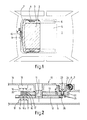
- Fig. 1 is a schematic plan view of a vehicle roof having an electric open roof construction according to the invention.
- Fig. 2 is an enlarged sectional view along the line II-II of Fig. 1.
- Fig. 3 is a perspective exploded view of the most important parts of the sectional view of Fig. 2.
- Fig. 1 shows in a schematic plan view an automobile roof 1 having a roof opening 2 therein.
- the embodiment of the electric open roof construction as shown is provided with a rigid panel 3 closing the roof opening 2 in its closed position and being movable from this closed position rearwardly below the fixed roof 1 in a slidable manner on the one hand, and to a backwardly and upwardly inclined ventilation position in a pivoting manner on the other hand.
- the invention can also be used in several other types of open roof constructions, such as spoiler roofs, open roofs having several panels or open roof constructions having other closure means than panels.
- each adjustment means 4 is driven by a pull and push cable 7.
- the pull and push cables 7 are provided with a helically wound thread 8 (see Fig. 2) with which a drive wheel of an electric motor 9 is engaged in order to displace the pull and push cable 7.
- the open roof construction comprises a device 10 for recognizing a number of specific positions of the panel 3, with which the electric motor 9 may be controlled.
- Fig. 2 and 3 show the most important parts of the device 10.
- the device 10 includes first of all two concentric rotary disks 12 and 13 being journalled on a common journal 11.
- the journal 11 is formed on a support 14 fixed to the frame 5.
- the first, and in this case lower, rotary disk 12 is provided with slots 15, 16a and b and 17 shaped as a segment of a circle and serving as switching means, while the second, upper rotary disk 13 comprises slots 16' and 17' being positioned on the same diameter as the respective slots 16 and 17 in the first rotary disk 12.
- the function of the slots 15, 16 and 17 serving as switching means will be elucidated furtheron.
- An optical detector 18 consisting of a transmitter positioned on the frame 5 and a receiver provided on the support 14, which are placed on both sides of the rotary disks 12 and 13, has three light paths 19, 20 and 21, which may be blocked by the disks 12 and 13, or are allowed to pass through the respective slots 15, 16 and 17 in the rotary disks 12 and 13.
- the blocking and passage of the light paths effect a switching action with which the electric motor 9 can be controlled.
- the lower rotary disk 12 and the upper rotary disk 13 are driven by a common transmission means 22 which is journalled about a journal 23 on the support 14 and has a special toothing 24 in engagement with the screw-thread 8 around the push and pull cable 7, such that a longitudinal sliding movement of the pull and push cable 7 causes a rotation of the transmission means 22.
- the transmission means 22 is provided with downwardly projecting pins 25 which may alternately come into engagement with radial grooves 26 in the first rotary disk 12, the pins 25 and the grooves 26 together forming a kind of maltese cross for intermittently rotating the first rotary disk 12.
- the transmission means 22 further includes a rectilineal-face toothing 27 being in engagement with a similar toothing 28 on the outer circumference of the second rotary disk 13 to rotate the second rotary disk 13.
- the reduction between the transmission means 22 and the first rotary disk 12 is a number of times larger than the reduction between the transmission means 22 and the second rotary disk 13, so that the second rotary disk 12 rotates a number of times faster than the first rotary disk 12.
- the transmission between the pull and push cable 7 and the first rotary disk 12 through the transmission means 22 is thereby chosen such that a full adjustment of the pull and push cable 7 between its both of its extreme positions causes a rotation of the lower rotary disk 12 of no more than 360°.
- each rotary position of the first rotary disk 12 consequently corresponds to only one single position of the panel 3.
- slots 15, 16 and 17 can indicate the following positions: slot 15 the tilted ventilating position of the panel 3, slot 16a the end of the ventilating position and possibly the end of the sliding position of the panel 3, and slot 16b and slot 17 the closed position of the panel 3.
- the several combinations of the transmitted and blocked light beams 19, 20 and 21 provide an univocal indication of the position of the panel 3. When for instance the light beams 19 and 21 are allowed to pass, then the panel 3 is in its extreme ventilating position, while the panel 3 is in its sliding position when all light beams 19, 20 and 21 are blocked.
- the accuracy of a switching point in the case shown at the end of the tilting and sliding movements of the panel and when the closed position thereof is obtained, will be determined by the rotational accuracy of the rotary disk 13. Only when the respective slots 16' and 17' are aligned with the respective slots 16 and 17 in the first rotary disk 12 and are aligned with the light beams 20 and 21 the particular position is detected and then it is for instance possible to produce a switching signal through a control circuit for stopping the electric motor 9.
Landscapes
- Engineering & Computer Science (AREA)
- Mechanical Engineering (AREA)
- Power-Operated Mechanisms For Wings (AREA)
Applications Claiming Priority (2)
| Application Number | Priority Date | Filing Date | Title |
|---|---|---|---|
| NL9000434 | 1990-02-23 | ||
| NL9000434A NL9000434A (nl) | 1990-02-23 | 1990-02-23 | Elektrische open-dakconstructie. |
Publications (2)
| Publication Number | Publication Date |
|---|---|
| EP0443216A1 true EP0443216A1 (fr) | 1991-08-28 |
| EP0443216B1 EP0443216B1 (fr) | 1993-08-11 |
Family
ID=19856654
Family Applications (1)
| Application Number | Title | Priority Date | Filing Date |
|---|---|---|---|
| EP90203258A Expired - Lifetime EP0443216B1 (fr) | 1990-02-23 | 1990-12-12 | Construction de toit ouvrant à moteur électrique |
Country Status (3)
| Country | Link |
|---|---|
| EP (1) | EP0443216B1 (fr) |
| DE (1) | DE69002753T2 (fr) |
| NL (1) | NL9000434A (fr) |
Cited By (3)
| Publication number | Priority date | Publication date | Assignee | Title |
|---|---|---|---|---|
| EP0560459A1 (fr) * | 1992-03-11 | 1993-09-15 | N.V. Nederlandsche Apparatenfabriek NEDAP | Dispositif pour la détermination de la position d'une organe mobile |
| US5612600A (en) * | 1995-10-17 | 1997-03-18 | Webasto Sunroofs Inc. | Position encoder system for a movable panel |
| FR2750815A1 (fr) * | 1996-07-05 | 1998-01-09 | Jidosha Denki Kogyo Kk | Circuit de commande de toit ouvrant |
Citations (3)
| Publication number | Priority date | Publication date | Assignee | Title |
|---|---|---|---|---|
| CH421535A (de) * | 1961-06-05 | 1966-09-30 | Fermat Limited | Vorrichtung zur Bestimmung der gegenseitigen Verschiebung und/oder Deckungsstellung von zwei Objekten |
| EP0351280A1 (fr) * | 1988-07-12 | 1990-01-17 | Rockwell-Cim | Ensemble motoréducteur à programmateur, destiné en particulier à la commande d'un toit ouvrant de véhicule automobile |
| DE3823869A1 (de) * | 1988-07-14 | 1990-01-18 | Webasto Ag Fahrzeugtechnik | Antriebsvorrichtung fuer einen ausstellbaren schiebedeckel eines kraftfahrzeugdaches |
Family Cites Families (1)
| Publication number | Priority date | Publication date | Assignee | Title |
|---|---|---|---|---|
| DE7629034U1 (de) * | 1976-09-17 | 1978-03-02 | Webasto-Werk W. Baier Gmbh & Co, 8031 Stockdorf | Betätigungsvorrichtung für einen ausstellbaren Schiebedeckel eines Kraftfahrzeugdaches |
-
1990
- 1990-02-23 NL NL9000434A patent/NL9000434A/nl not_active Application Discontinuation
- 1990-12-12 EP EP90203258A patent/EP0443216B1/fr not_active Expired - Lifetime
- 1990-12-12 DE DE1990602753 patent/DE69002753T2/de not_active Expired - Fee Related
Patent Citations (3)
| Publication number | Priority date | Publication date | Assignee | Title |
|---|---|---|---|---|
| CH421535A (de) * | 1961-06-05 | 1966-09-30 | Fermat Limited | Vorrichtung zur Bestimmung der gegenseitigen Verschiebung und/oder Deckungsstellung von zwei Objekten |
| EP0351280A1 (fr) * | 1988-07-12 | 1990-01-17 | Rockwell-Cim | Ensemble motoréducteur à programmateur, destiné en particulier à la commande d'un toit ouvrant de véhicule automobile |
| DE3823869A1 (de) * | 1988-07-14 | 1990-01-18 | Webasto Ag Fahrzeugtechnik | Antriebsvorrichtung fuer einen ausstellbaren schiebedeckel eines kraftfahrzeugdaches |
Cited By (3)
| Publication number | Priority date | Publication date | Assignee | Title |
|---|---|---|---|---|
| EP0560459A1 (fr) * | 1992-03-11 | 1993-09-15 | N.V. Nederlandsche Apparatenfabriek NEDAP | Dispositif pour la détermination de la position d'une organe mobile |
| US5612600A (en) * | 1995-10-17 | 1997-03-18 | Webasto Sunroofs Inc. | Position encoder system for a movable panel |
| FR2750815A1 (fr) * | 1996-07-05 | 1998-01-09 | Jidosha Denki Kogyo Kk | Circuit de commande de toit ouvrant |
Also Published As
| Publication number | Publication date |
|---|---|
| EP0443216B1 (fr) | 1993-08-11 |
| DE69002753D1 (de) | 1993-09-16 |
| DE69002753T2 (de) | 1994-07-21 |
| NL9000434A (nl) | 1991-09-16 |
Similar Documents
| Publication | Publication Date | Title |
|---|---|---|
| US6758452B1 (en) | Support for a drinks holder | |
| US5218282A (en) | Automatic door operator including electronic travel detection | |
| US5635809A (en) | Actuating-element positioning servo-drive device | |
| US4640590A (en) | Apparatus providing rapid adjustment of a mirror | |
| US5986421A (en) | Safety device for power window | |
| JPH0344934B2 (fr) | ||
| JP2001515188A (ja) | 操縦装置 | |
| EP0443216B1 (fr) | Construction de toit ouvrant à moteur électrique | |
| CA2112604A1 (fr) | Appareil de lancage de liquide | |
| FR2638230A1 (fr) | Dispositif pour determiner la position d'une piece mecanique notamment d'un levier de changement de vitesse | |
| EP0155410B1 (fr) | Dispositif de manivelle pour toit ouvrant d'un véhicule | |
| US6297606B1 (en) | Sunroof controlling device | |
| FR2754220B1 (fr) | Systeme de commande du fonctionnement de modules a motoreducteur a double sens de rotation, de reglage en position d'elements d'un siege de vehicule | |
| JPH08145657A (ja) | 移動体の位置検出装置 | |
| DE3533056C2 (fr) | ||
| US6100657A (en) | Electric motor drive | |
| GB2306702A (en) | Monitoring movement of a part | |
| US7980154B2 (en) | Gearbox shifting device and gearbox comprising a gearbox shifting device | |
| US6504964B1 (en) | Optical member switching apparatus for electronically switching a plurality of optical members in correspondence with an object to be inspected by a microscope | |
| JPH0420141Y2 (fr) | ||
| US4272175A (en) | Automatic aperture control device | |
| EP0301379A1 (fr) | Dispositif de commande pour un système de climatisation de véhicule automobile | |
| JPS55140612A (en) | Automatic closing device for ceiling window | |
| JPH0616140Y2 (ja) | 電動式開閉戸のリミツトスイツチ構造 | |
| US5244068A (en) | Device for limiting the number of revolutions of a shaft of a rotary drive for a sliding roof of an automobile |
Legal Events
| Date | Code | Title | Description |
|---|---|---|---|
| PUAI | Public reference made under article 153(3) epc to a published international application that has entered the european phase |
Free format text: ORIGINAL CODE: 0009012 |
|
| AK | Designated contracting states |
Kind code of ref document: A1 Designated state(s): DE FR GB IT NL SE |
|
| 17P | Request for examination filed |
Effective date: 19920224 |
|
| 17Q | First examination report despatched |
Effective date: 19921027 |
|
| GRAA | (expected) grant |
Free format text: ORIGINAL CODE: 0009210 |
|
| AK | Designated contracting states |
Kind code of ref document: B1 Designated state(s): DE FR GB IT NL SE |
|
| REF | Corresponds to: |
Ref document number: 69002753 Country of ref document: DE Date of ref document: 19930916 |
|
| ITF | It: translation for a ep patent filed | ||
| ET | Fr: translation filed | ||
| PLBE | No opposition filed within time limit |
Free format text: ORIGINAL CODE: 0009261 |
|
| STAA | Information on the status of an ep patent application or granted ep patent |
Free format text: STATUS: NO OPPOSITION FILED WITHIN TIME LIMIT |
|
| 26N | No opposition filed | ||
| EAL | Se: european patent in force in sweden |
Ref document number: 90203258.0 |
|
| REG | Reference to a national code |
Ref country code: GB Ref legal event code: IF02 |
|
| NLS | Nl: assignments of ep-patents |
Owner name: WEBASTOHOLLANDIA HOLDING B.V. |
|
| NLT1 | Nl: modifications of names registered in virtue of documents presented to the patent office pursuant to art. 16 a, paragraph 1 |
Owner name: WEBASTOHOLLANDIA OCTROOIEN B.V. Owner name: WEBASTO PRODUCT INTERNATIONAL NL B.V. |
|
| PGFP | Annual fee paid to national office [announced via postgrant information from national office to epo] |
Ref country code: FR Payment date: 20031125 Year of fee payment: 14 |
|
| PGFP | Annual fee paid to national office [announced via postgrant information from national office to epo] |
Ref country code: GB Payment date: 20031210 Year of fee payment: 14 |
|
| PGFP | Annual fee paid to national office [announced via postgrant information from national office to epo] |
Ref country code: SE Payment date: 20031216 Year of fee payment: 14 |
|
| PGFP | Annual fee paid to national office [announced via postgrant information from national office to epo] |
Ref country code: NL Payment date: 20031231 Year of fee payment: 14 Ref country code: DE Payment date: 20031231 Year of fee payment: 14 |
|
| PG25 | Lapsed in a contracting state [announced via postgrant information from national office to epo] |
Ref country code: GB Free format text: LAPSE BECAUSE OF NON-PAYMENT OF DUE FEES Effective date: 20041212 |
|
| PG25 | Lapsed in a contracting state [announced via postgrant information from national office to epo] |
Ref country code: SE Free format text: LAPSE BECAUSE OF NON-PAYMENT OF DUE FEES Effective date: 20041213 |
|
| PG25 | Lapsed in a contracting state [announced via postgrant information from national office to epo] |
Ref country code: NL Free format text: LAPSE BECAUSE OF NON-PAYMENT OF DUE FEES Effective date: 20050701 Ref country code: DE Free format text: LAPSE BECAUSE OF NON-PAYMENT OF DUE FEES Effective date: 20050701 |
|
| EUG | Se: european patent has lapsed | ||
| GBPC | Gb: european patent ceased through non-payment of renewal fee |
Effective date: 20041212 |
|
| PG25 | Lapsed in a contracting state [announced via postgrant information from national office to epo] |
Ref country code: FR Free format text: LAPSE BECAUSE OF NON-PAYMENT OF DUE FEES Effective date: 20050831 |
|
| NLV4 | Nl: lapsed or anulled due to non-payment of the annual fee |
Effective date: 20050701 |
|
| REG | Reference to a national code |
Ref country code: FR Ref legal event code: ST |
|
| PG25 | Lapsed in a contracting state [announced via postgrant information from national office to epo] |
Ref country code: IT Free format text: LAPSE BECAUSE OF NON-PAYMENT OF DUE FEES;WARNING: LAPSES OF ITALIAN PATENTS WITH EFFECTIVE DATE BEFORE 2007 MAY HAVE OCCURRED AT ANY TIME BEFORE 2007. THE CORRECT EFFECTIVE DATE MAY BE DIFFERENT FROM THE ONE RECORDED. Effective date: 20051212 |