EP0443232A1 - Appareil et procédé pour pulvériser des matériaux en déplacement - Google Patents
Appareil et procédé pour pulvériser des matériaux en déplacement Download PDFInfo
- Publication number
- EP0443232A1 EP0443232A1 EP90301922A EP90301922A EP0443232A1 EP 0443232 A1 EP0443232 A1 EP 0443232A1 EP 90301922 A EP90301922 A EP 90301922A EP 90301922 A EP90301922 A EP 90301922A EP 0443232 A1 EP0443232 A1 EP 0443232A1
- Authority
- EP
- European Patent Office
- Prior art keywords
- stream
- marking material
- web
- nozzle
- substrate
- Prior art date
- Legal status (The legal status is an assumption and is not a legal conclusion. Google has not performed a legal analysis and makes no representation as to the accuracy of the status listed.)
- Ceased
Links
Images


Classifications
-
- D—TEXTILES; PAPER
- D06—TREATMENT OF TEXTILES OR THE LIKE; LAUNDERING; FLEXIBLE MATERIALS NOT OTHERWISE PROVIDED FOR
- D06B—TREATING TEXTILE MATERIALS USING LIQUIDS, GASES OR VAPOURS
- D06B11/00—Treatment of selected parts of textile materials, e.g. partial dyeing
- D06B11/0056—Treatment of selected parts of textile materials, e.g. partial dyeing of fabrics
- D06B11/0059—Treatment of selected parts of textile materials, e.g. partial dyeing of fabrics by spraying
-
- B—PERFORMING OPERATIONS; TRANSPORTING
- B05—SPRAYING OR ATOMISING IN GENERAL; APPLYING FLUENT MATERIALS TO SURFACES, IN GENERAL
- B05B—SPRAYING APPARATUS; ATOMISING APPARATUS; NOZZLES
- B05B12/00—Arrangements for controlling delivery; Arrangements for controlling the spray area
- B05B12/02—Arrangements for controlling delivery; Arrangements for controlling the spray area for controlling time, or sequence, of delivery
- B05B12/06—Arrangements for controlling delivery; Arrangements for controlling the spray area for controlling time, or sequence, of delivery for effecting pulsating flow
-
- B—PERFORMING OPERATIONS; TRANSPORTING
- B05—SPRAYING OR ATOMISING IN GENERAL; APPLYING FLUENT MATERIALS TO SURFACES, IN GENERAL
- B05B—SPRAYING APPARATUS; ATOMISING APPARATUS; NOZZLES
- B05B13/00—Machines or plants for applying liquids or other fluent materials to surfaces of objects or other work by spraying, not covered by groups B05B1/00 - B05B11/00
- B05B13/02—Means for supporting work; Arrangement or mounting of spray heads; Adaptation or arrangement of means for feeding work
- B05B13/0207—Means for supporting work; Arrangement or mounting of spray heads; Adaptation or arrangement of means for feeding work the work being an elongated body, e.g. wire or pipe
-
- B—PERFORMING OPERATIONS; TRANSPORTING
- B05—SPRAYING OR ATOMISING IN GENERAL; APPLYING FLUENT MATERIALS TO SURFACES, IN GENERAL
- B05B—SPRAYING APPARATUS; ATOMISING APPARATUS; NOZZLES
- B05B14/00—Arrangements for collecting, re-using or eliminating excess spraying material
-
- B—PERFORMING OPERATIONS; TRANSPORTING
- B05—SPRAYING OR ATOMISING IN GENERAL; APPLYING FLUENT MATERIALS TO SURFACES, IN GENERAL
- B05B—SPRAYING APPARATUS; ATOMISING APPARATUS; NOZZLES
- B05B7/00—Spraying apparatus for discharge of liquids or other fluent materials from two or more sources, e.g. of liquid and air, of powder and gas
- B05B7/02—Spray pistols; Apparatus for discharge
- B05B7/06—Spray pistols; Apparatus for discharge with at least one outlet orifice surrounding another approximately in the same plane
- B05B7/062—Spray pistols; Apparatus for discharge with at least one outlet orifice surrounding another approximately in the same plane with only one liquid outlet and at least one gas outlet
- B05B7/066—Spray pistols; Apparatus for discharge with at least one outlet orifice surrounding another approximately in the same plane with only one liquid outlet and at least one gas outlet with an inner liquid outlet surrounded by at least one annular gas outlet
-
- B—PERFORMING OPERATIONS; TRANSPORTING
- B05—SPRAYING OR ATOMISING IN GENERAL; APPLYING FLUENT MATERIALS TO SURFACES, IN GENERAL
- B05B—SPRAYING APPARATUS; ATOMISING APPARATUS; NOZZLES
- B05B7/00—Spraying apparatus for discharge of liquids or other fluent materials from two or more sources, e.g. of liquid and air, of powder and gas
- B05B7/02—Spray pistols; Apparatus for discharge
- B05B7/08—Spray pistols; Apparatus for discharge with separate outlet orifices, e.g. to form parallel jets, i.e. the axis of the jets being parallel, to form intersecting jets, i.e. the axis of the jets converging but not necessarily intersecting at a point
- B05B7/0807—Spray pistols; Apparatus for discharge with separate outlet orifices, e.g. to form parallel jets, i.e. the axis of the jets being parallel, to form intersecting jets, i.e. the axis of the jets converging but not necessarily intersecting at a point to form intersecting jets
-
- B—PERFORMING OPERATIONS; TRANSPORTING
- B05—SPRAYING OR ATOMISING IN GENERAL; APPLYING FLUENT MATERIALS TO SURFACES, IN GENERAL
- B05B—SPRAYING APPARATUS; ATOMISING APPARATUS; NOZZLES
- B05B7/00—Spraying apparatus for discharge of liquids or other fluent materials from two or more sources, e.g. of liquid and air, of powder and gas
- B05B7/02—Spray pistols; Apparatus for discharge
- B05B7/08—Spray pistols; Apparatus for discharge with separate outlet orifices, e.g. to form parallel jets, i.e. the axis of the jets being parallel, to form intersecting jets, i.e. the axis of the jets converging but not necessarily intersecting at a point
- B05B7/0884—Spray pistols; Apparatus for discharge with separate outlet orifices, e.g. to form parallel jets, i.e. the axis of the jets being parallel, to form intersecting jets, i.e. the axis of the jets converging but not necessarily intersecting at a point the outlet orifices for jets constituted by a liquid or a mixture containing a liquid being aligned
-
- D—TEXTILES; PAPER
- D06—TREATMENT OF TEXTILES OR THE LIKE; LAUNDERING; FLEXIBLE MATERIALS NOT OTHERWISE PROVIDED FOR
- D06M—TREATMENT, NOT PROVIDED FOR ELSEWHERE IN CLASS D06, OF FIBRES, THREADS, YARNS, FABRICS, FEATHERS OR FIBROUS GOODS MADE FROM SUCH MATERIALS
- D06M23/00—Treatment of fibres, threads, yarns, fabrics or fibrous goods made from such materials, characterised by the process
- D06M23/06—Processes in which the treating agent is dispersed in a gas, e.g. aerosols
-
- Y—GENERAL TAGGING OF NEW TECHNOLOGICAL DEVELOPMENTS; GENERAL TAGGING OF CROSS-SECTIONAL TECHNOLOGIES SPANNING OVER SEVERAL SECTIONS OF THE IPC; TECHNICAL SUBJECTS COVERED BY FORMER USPC CROSS-REFERENCE ART COLLECTIONS [XRACs] AND DIGESTS
- Y02—TECHNOLOGIES OR APPLICATIONS FOR MITIGATION OR ADAPTATION AGAINST CLIMATE CHANGE
- Y02P—CLIMATE CHANGE MITIGATION TECHNOLOGIES IN THE PRODUCTION OR PROCESSING OF GOODS
- Y02P70/00—Climate change mitigation technologies in the production process for final industrial or consumer products
- Y02P70/10—Greenhouse gas [GHG] capture, material saving, heat recovery or other energy efficient measures, e.g. motor control, characterised by manufacturing processes, e.g. for rolling metal or metal working
Definitions
- the present invention is directed to an apparatus and method for spraying liquids onto a moving substrate. More particularly, the invention disclosed herein relates to an apparatus and method by which a moving substrate may be patterned with a discrete and/or diffuse pattern. It is particularly suitable for the application of dye, ink, or other marking liquids to moving textile materials, such as fabrics, carpets, and the like.
- marking liquids shall include, in addition to dyes, inks, and the like, materials which serve to bleach or otherwise modify a previously dyed substrate, as well as materials which, when applied, prevent, retard, or otherwise modify the action of one or more dyes applied subsequently.
- a stream of dye is directed at the desired substrate, and a transverse stream of a control fluid is used to divert the stream into a barrier, catch basin, or the like, in response to externally supplied pattern information or otherwise, when no dye on the substrate is desired.
- a curtain of dye is directed in closely-spaced, parallel relation to the desired substrate, and one or more streams of a control fluid are directed through the curtain in the direction of the substrate, thereby causing displacement of dye from the curtain onto the substrate.
- a third approach as set forth, for example, in U.S. Patent No.
- a stream of a control fluid such as air is directed into a mixing chamber in which a quantity of dye is introduced in accordance with pattern information.
- the chamber may be positioned in close proximity to the desired substrate, and may be configured so that, for example, air enters the chamber from the top, intersects a flow of dye entering the chamber from the side, and causes a spray of air and dye to exit from the confines of the chamber, via a conduit extending from the bottom of the chamber, onto the desired substrate.
- Such products may be divided into two basic categories.
- the first may be called a "diffuse pattern” product, in which the desired substrate has been dyed in a pattern which exhibits soft, diffused color boundaries and perhaps exhibits color hues which overlap and blend almost imperceptibly from one to another, and which product may exhibit literally dozens or hundreds of different colors, shades, or hues over the pattern area.
- the second category may be called a "random pattern” product, in which the distribution of color within areas on the substrate - or over the entire substrate - has a random or pseudo-random appearance.
- the color may be in the form of extremely small flecks or specks, or may be in the form of larger areas having irregular, random-appearing borders.
- Such products often may exhibit characteristics which are a combination of these two categories, wherein, for example, irregularly shaped patches of color exhibit diffused boundaries and contain a multitude of varying shades or hues, and which, optionally, may contain randomly distributed and/or overlapping specks of color in localized areas of the substrate.
- any system which depends upon the rapid interruption of the flow of a liquid dye must deal with "water hammer” effects, which can seriously degrade patterning performance and cause damage to the valves and conduits of the apparatus, as well as the problem of preventing the dye from contacting the substrate during "no pattern” intervals and satisfactorily containing such dye.
- the present invention is directed to an apparatus and method by which, in a preferred embodiment, several arrays of closely spaced streams of liquid dye or ink are normally directed into corresponding collection troughs; in a preferred embodiment, a diverting surface or lip is used to intercept the streams and channel the liquid dye into the respective collection trough.
- Each stream in a given array has associated with it a source of pressurized air or other fluid which, on command, forms and directs an atomizing stream or jet of such fluid on a path which brings the atomizing fluid stream into contact with the liquid dye or ink, whereby the streams of ink or dye are transformed into a mist of variously sized diverging droplets of ink or dye which are propelled, by the combined momentum of the liquid and air streams, in the direction of the substrate to be marked.
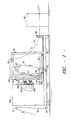
- Figure 1 schematically depicts an elevation view of an apparatus embodying the invention which may be used to pattern a continuous web of substrate.
- Figure 2 shows, in schematic form, a spray generator array of the type depicted at 100 in Figure 1, and the associated dye and air handling apparatus.
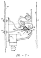
- Figure 3 depicts, in a cross section taken along a vertical plane perpendicular to the longitudinal axis of array 100 and bisecting dye pipe 130, a side view of the spray generator of Figure 2.
- Figure 4 depicts a plan view of a portion of the array 100 shown in Figure 2, as seen along line IV-IV of Figure 3.
- Figure 5 depicts a section view of a portion of a spray generator illustrating one position of dye nozzle 132 of Figure 3, as seen along line V-V of Figure 4
- Figure 6 is a view similar to Figure 5, showing nozzle 132 in a different position.
- Figure 7 depicts a portion of the array 100 as seen along lines VII-VII of Figure 5.
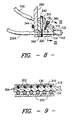
- Figure 8 is a section view, taken along line VIII-VIII of Figure 7.
- Figure 9 is a section view taken along line IX-IX of Figure 8, depicting the "V"-shaped notches useful in aligning the intersecting air and dye streams.
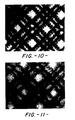
- Figures 10 through 14 are photomicrographs (0.2X) showing the face of the patterned knitted fabric of Example 1.
- Figure 15 is a photomicrograph (1.1x) showing the face of the patterned woven fabric of Example 2.
- Figure 1 shows, diagrammatically, an overall side elevation view of apparatus suitable for patterning a web of moving substrate material in accordance with the teachings herein. While any substrate material capable of being dyed or otherwise patterned by the procedures set forth below may be used, a preferred material is a textile substrate such as fabric or carpet in web form; the term fabric shall be used hereinafter without intending to restrict unnecessarily the generality of the discussion hereinbelow.
- Fabric web 10 is supplied from any suitable source, and is drawn over rolls 12, 14 and under valve house 200 to roll 16, which rotates in bearings associated with platform 26.
- Substrate 10 is then directed into the interior of rolling frame 20, which is supported on wheels 22 and which may be moved along track 24 to adjust the distance between frame 20 and valve house 200, and, correspondingly, between arrays 100 and the surface of substrate 10. This permits the effects of changing the spacing between arrays 100 and the face of substrate 10 to be easily and immediately observed.
- Substrate 10 is directed around rolls 40, 42 and 44 and through driven nip rolls 46, 48 and is then presented, in a preferred embodiment, in a substantially vertical orientation to the multiple arrays 100 of spray generators mounted on the face of valve house 200.
- the substrate 10 may be separated from an appropriate backing member 50, which may be comprised of plastic or other dye-impervious material, by spacers 52, 54 positioned along the top and bottom edges of backing member 50 above and below the level of the spray generator arrays 100, thereby assuring no contact between the back of substrate 10 and the backing member 50. This prevents unwanted smearing on the back of the fabric and prevents excessive saturation or accumulation of dye visible on the face of the fabric.
- lower spacer 52 may be in the form of a trough-like collector which can serve to collect the sprayed liquid which may pass through substrate 10 and collect on backing member 50.
- Substrate 10 is then directed over roll 60 and over tension-generating roll 62, which may have a surface covered with rubber or the like and which may be overdriven, to assure that substrate 10 is relatively taut in the region opposite arrays 100. As shown, substrate 10 may then be guided to an appropriate dye fixation means 30 or other post treatment processor.
- Figures 2 and 3 illustrate, in varying degrees of detail, a preferred embodiment of the spray generator of the type depicted at 100 in Figure 1.
- Figure 3 depicts a partial cross-section view along a vertical plane perpendicular to the longitudinal axis of array 100 and through the longitudinal axis of a dye pipe 130 of Figure 2.
- the elongate array 100 is comprised of a plurality of individual spray generators, each comprised of a dye pipe 130 and nozzle 132 through which a liquid dye, ink, or other marking material may be pumped, and a dispersing aperture 140 and associated surround 142, through which a relatively high pressure dispersing fluid such as, for example, air or other gas, may be propelled.
- the individual spray generators are mounted in alignment, with an adjacent spacing appropriate to the degree of definition desired. It is believed adjacent lateral spacings of between about 0.2 inch and 1.0 inch, measured from the centerlines of adjacent dispersing apertures 140 along array 100, may be used with good results. Spacings outside this range may be used if, for example, minimal overlap between adjacent spray patterns on the substrate is desired.
- dye will be assumed to be the marking material of choice and air will be assumed to be the dispersing fluid of choice, although other marking materials and other gases or fluids may be used for particular purposes.
- each generator further associated with each generator is an electronically controlled valve 260 which is interposed in the pressurized air lines 202 and 204 which serve to supply aperture 140 with pressurized air from manifold 220, which in turn is suitably connected, via regulator 206 and filter 208, to a source 210 of pressurized air.
- Valves 260 are, in a preferred embodiment, of the electrically actuated pneumatic type such as those distributed by the Lee Company of Westport, Connecticut.
- dye supply line 102 which extends from dye manifold 120, which in turn is fed, via pressurizing pump 114 and filter 112 and associated conduits, from dye reservoir 110.
- Dye conduits 104 and 106 supply reservoir 110 with excess dye from manifold 120 and captured dye expelled by nozzle 132 ( Figure 3) into containment trough 162, thus forming, in a preferred embodiment, a recirculating dye system.
- Elongated wedge-shaped array frame 110 is constructed with a series of parallel "V"-shaped notches or grooves 302, 304, spaced along its length (see Figure 9) in precisely opposed pairs along the top and bottom of frame 110 at intervals corresponding to the desired spacing between adjacent dye pipes 130 and apertures 140.
- Air conduits 114 may then be placed within "V"-shaped grooves 304 directly opposite corresponding dye pipes 130, and attached to respective air lines 202.
- Dye pipe positioning plate 310 and air conduit positioning plate 320 secured to frame 110 via laterally spaced bolts 342, maintain dye pipes 130 and air conduits 114 within their respective "V"-shaped grooves. Due to the self-centering nature of the "V"-shaped grooves 302, 304 (as compared with other possible groove cross-section shapes), no additional alignment technique is needed, provided grooves 302 and 304 have been placed directly opposite one another. Alignment pins 345 may be used to insure correct mounting alignment of the positioning plate with respect to Frame 10.
- the array 100 comprising frame 110 and positioning plates 310, 320, is suitable attached, via rigid member 290 and mounting bolts 344, to the front face 212 of valve house 200.
- angle shown between dye pipes 130 and air conduits 114 is depicted as approximately thirty degrees, this merely represents a preferred embodiment. Angles less than and greater than that shown may be advantageously employed under some conditions, so long as the resulting pressurized dye stream is not sent on a trajectory from nozzle 132 which, in the absence of an interacting burst or stream of gas, results in continuous contact with the substrate.
- Air conduit 114 is tapered so that air at pressures of 60 p.s.i.g. or more may be transferred to replaceable port aperture 140 from supply line 202 (of which two are depicted in Figure 3, merely to indicate a suggested arrangement for closely adjacent lines 202).
- Supply line 202 is connected to air manifold 220 ( Figure 2) via fittings 214 in front wall 212 of valve house 200.
- air valves 260 are situated in close proximity to fittings 214, and may be arranged on a pneumatic circuit board analogous to an electronic circuit board.
- valve card may be equipped with suitable mating fittings so that a valve card, on which have been arranged a plurality of individual air valves for individually controlling a corresponding plurality of individual spray generators, may be merely plugged into corresponding fittings 214 mounted on the inside of front wall 212.
- a suitable number of valves 260 as depicted in Figure 2 may be considered to be individually mounted on one such a valve card with multiple valve cards mounted in adjacent fashion to provide control along the length of the entire array 100.
- aperture 140 Associated with aperture 140 is shroud or surround 142, through which nozzle 132 may extend via surround port 144.
- Surround 142 tends to maintain the high velocity of the dispersing medium jet formed by aperture 140 and to focus the jet in the direction of the substrate. Operation without surround 142 or a similar confining enclosure would result in a process which would generate an undesirable cloud or mist of dye which would be difficult to control in terms of placement, degree of mixing of adjacent sprays, etc.
- Nozzle 132 supplied with slightly pressurized dye via dye supply line 102 and dye supply manifold 120, is associated with pipe 130 which fits within "V"-shaped groove 302 of wedge 110.
- the relative position of nozzle 132 within surround 142 may be adjusted, as is shown in Figures 5 and 6, by moving pipe 130 within groove 302 and locking pipe 130 in the desired position by means of set screw 340.
- This adjustment has been found to alter the character of the spray by changing the radial distance from the axis of the air jet emerging from apertune 140, and therefore changing the character (e.g., velocity, pressure, etc.) of the region within the air jet at which the dye is ejected from the protected confines of nozzle 132.
- nozzle 132 may be located substantially above the axis of aperture 140, it is preferred that nozzle 132 be positioned within surround 142. In a particularly preferred embodiment, the tip of nozzle 132 is positioned at most a short radial distance from the axis of aperture 140 so that, whenever the gas stream associated with aperture 140 is actuated, the liquid emanating from nozzle 132 is immediately acted upon by the jet and does not have the opportunity to form a defined, coherent stream except during interruptions in the flow of gas from aperture 140.
- a diverting lip or surface 160 Perpendicular to the longitudinal axis of dye nozzle 132 and, in the embodiment shown in the Figures, generally situated opposite aperture 140 and parallel to array 100, is a diverting lip or surface 160.
- Surface 160 is mounted so that dye exiting from nozzle 132 will, in the absence of a disturbing air stream from aperture 140, form a stream which travels in a trajectory which terminates on diverting surface 160 and flows into an associated containment trough 162. From trough 162, the dye may be pumped, via dye basin 164 and conduit 106, back to dye reservoir 110 for re-use, or may be pumped to a suitable waste receptacle.
- surface 160 may be mounted inside trough 162 to extend upwardly therefrom, and is preferably mounted via a suitable adjusting means of conventional design so that the degree to which surface 160 extends into or beyond the path of the dye stream, as well as the relative spacing and alignment of the surface 160 with respect to the plurality of nozzles 132 and surrounds 142 in array 100, may be adjusted. It is contemplated that surface 160 may be relatively rigid or may be a relatively thin, flexible blade which is given rigidity by clamping each end of the blade and applying suitable tension along the length of the blade.
- the continuous stream of liquid dye tends to produce some droplets which are substantially larger than the fine mist ordinarily associated with an atomization process such as is employed herein.
- the term “microscopic fragmentation” shall be used to describe the process whereby the liquid dye is broken up into a relatively fine mist, i.e., where droplet average diameter is generally substantially smaller than about 0.1 or 0.2 millimeter.
- the term “macroscopic fragmentation” shall be used to describe the process whereby the liquid dye is broken up into droplets having an average diameter on the order of about 0.1 or 0.2 millimeter, or larger.
- the dye stream is atomized in the region of the stream directly in line with the advancing wave front of pressurized air, which results in microscopic fragmentation of the dye. That portion of the dye stream immediately above or below this in-line region remains coherent, but tends to become entrained in the periphery of the passing air stream and tends to separate into relatively large droplets and irregularly shaped spatters of dye (i.e., it undergoes macroscopic fragmentation) which are propelled toward the substrate.
- Some dye is pushed downwardly into the collection trough 162, but some is pushed upwardly, toward the edge of diverting surface 160, and is ultimately pushed over the edge and is carried by the air stream toward the substrate, in the form of larger droplets and irregularly shaped spatters (i.e., products of macroscopic fragmentation).
- Valves 260 associated with air supply lines 202 prevent air from passing through port aperture 140.
- ink is permitted to stream from nozzle 132 to diverting surface 160 without interruption as shown in Figures 3 and 4, where it is dissipated and collected in containment trough 162 and drip basin 164, and, ultimately, pumped back to dye supply manifold 120 in pressurized form or discarded.
- Figures 5 and 6 depict the dye applicator in operation where pulses of air, generated by the rapid actuation and deactuation of valves 260, are being supplied to aperture 140.
- pressurized air entering bore 114 and passing through aperture 140 forms a jet which interacts with the dye which normally flows in a continuous, uninterrupted stream from the tip of nozzle 132 to a location on face of diverting surface 160.
- the tip of nozzle 132 is positioned within the region occupied by the jet, so that the dye is acted upon immediately as it exits from nozzle 132. This position tends to suppress the formation of the relatively larger spatters, flecks, and blotches associated with macroscopic fragmentation, and tends to encourage the fine mist formation associated with microscopic fragmentation.
- the stream of relatively low pressure dye typically about 0.2 to about 4 p.s.i.g.
- the stream or jet of relatively high pressure air typically about 5 to about 60 p.s.i.g.
- the ratio of dispersing material pressure to marking material pressure will generally fall within a range of about 5 to about 60, but may fall outside this range under certain conditions. For example, if high viscosity marking materials are used, higher than usual dispersing material pressures may be desirable, causing the above ratio to exceed 60.
- a variety of different sized droplets are produced, which are generally propelled in the direction of the surface of moving substrate web 10, which typically may be positioned from about one to about twelve inches from nozzles 132.
- the viscosity of the dye By varying the respective pressures of the dye and air streams, the viscosity of the dye, the degree to which nozzle 132 protrudes through surround port 144 and intrudes into the air stream or jet flowing from aperture 140, as well as other factors (for example, the degree to which containment lip is made to extend into the area in which the dye spray is generated, the distance between nozzle 132 and diverting surface 160, and the distance between nozzle 132 and substrate 10), a wide variety of visually attractive commercial products may be generated in a reproducible manner.
- the adjacent spacing of the individual nozzles 132 and apertures 140 comprising the plurality of spray generators spaced along the longitudinal axis of array 100 is generally fixed for a given apparatus in order to maintain proper alignment.
- This spacing is preferably such that, for a given nozzle-to-substrate distance, the spray patterns from immediately adjacent spray generators have substantially overlapping trajectories, allowing for the overlapping and mixing of the spray patterns throughout a relatively large percentage of the spray path between nozzles 132 and the surface of substrate 10, as depicted in Figure 7.
- the included angle of the spray pattern may be on the order of about 25 to about 50 degrees
- the adjacent spacing may be about 0.3 to about 0.6 inch
- the nozzle-to-substrate distance may be from about two to about eight inches; under such conditions, the overlap and mixing of sprays generated not only from immediately adjacent nozzles 132, but from nozzles 132 spaced two or more nozzle spacings away, has been observed. It is believed such substantial mixing and overlapping of the individual spray patterns while the spray droplets are moving toward the substrate contributes greatly to the blending and diffusion which characterizes the "diffuse pattern" product.
- valves 260 controlling the flow of air to aperture 140 are actuated by means of computer control indicated in Figure 2 at 270, which permits each of the individual dye streams to be selectively interrupted in response to externally supplied pattern data, thereby providing the capability of reproducing complex patterns.
- Computer control may also be used to accommodate variations in dye pick-up or dye deposition requirements among different types of substrates, as well as variations in the speed of the substrate as it is drawn through the apparatus. This may be achieved in a manner similar to that disclosed in U.S. Patent Nos. 3,894,413; 3,969,779; or 4,033,154.
- a rotary motion digital encoder is associated with the movement of the substrate through frame 20. This provides a signal corresponding to the linear travel of the substrate 10, which may then be used to meter a predetermined quantity of dye onto a fixed length or area of substrate in a repeatable manner.
- a cycle time T may be defined as that period of time which corresponds to the time necessary for the substrate to travel some small distance representing the limit of pattern detail desired in the direction of substrate travel, e.g., 0.1 inch.
- 0.1 inch of substrate travel corresponds to 100 milliseconds. Therefore, in the case where 0.1 inch is chosen as the minimum level of pattern detail desired along the length of the web, and where the web speed is five feet per minute, the cycle time T will be set at 100 milliseconds.
- This cycle time T not only represents the time interval necessary for the web to advance 0.1 inch, but also represents the time interval between the initiation of one burst of air (and, therefore, spray of dye) and the initiation of the next burst of air.
- the desired duration of each burst of air within each 100 millisecond cycle, and therefore the duration of the dye spray directed at the substrate, may be determined by considering the amount of dye pick-up or dye deposition requirements dictated by the nature of the dye and substrate used.
- the role of the patterning data is to specify, by pattern command, the requisite number of individual 100 millisecond cycles in which the air supply for each of the spray generators will be actuated in order to form the necessary groups of dye droplet needed to generate the required pattern or cover the proper area of substrate with the proper quantity of dye.
- the overall effect is the generation of a series of spaced groups of discrete droplet sprays or clouds emanating from each spray generator, wherein the individual cloud size and spacing between cloud groups is determined by the pattern data, the nature of the dye and substrate, etc.
- the air supply associated with each spray generator along array 100 needed for patterning at that time may be switched on for 20 milliseconds then switched off for 80 milliseconds, then switched on for 20 milliseconds, etc., thereby forming bursts of spray droplets of a uniform size (i.e., that size generated by a 20 millisecond burst of air) at 100 millisecond intervals, until the number of on/off cycles dictated by the pattern data for that specific spray generator has occurred. If the substrate is now slowed to half its former speed, the time taken for the web to advance 0.1 inch is now doubled, therefore doubling cycle time T.
- the "dwell time" of the substrate in front of the spray generators is now twice its former value. However, the rate at which dye is applied by the individual spray generators when the air supply is switched on is constant. If the same quantity of dye is to be applied within the 0.1 inch expanse of substrate as before, the elapsed time the air supply is on remains at its previously determined level, i.e., 20 milliseconds; the off time, however, must be extended to provide for an overall cycle time equal to the new time taken for the substrate to advance 0.1 inch. In this example, therefore, slowing the substrate speed to half its former value will cause the aforementioned computer control to generate bursts of spray droplets of the same size as before, but at 200 millisecond intervals.
- Dyes or other marking materials having a wide variety of flow characteristics have been used; generally speaking, higher viscosity liquids tend to increase the degree of macroscopic fragmentation which occurs, while lower viscosity liquids tend to increase the degree of observed microscopic fragmentation.
- Various thickeners, thixotropic agents, surface tension modifiers, and the like have been used with interesting results. For example, use of agents such as guar gum which cause the liquid dye to become "stringy" causes the resulting pattern of dye on the substrate to contain a random line segment pattern element which somewhat resembles portions of a spider web, and which contains blobs or irregularly shaped nodes of dye positioned at various intervals along the length of the line segments.
- a 100% polyester knit fabric having 16 wales per inch and 34 courses per inch and a weight of approximately 1.36 pounds per linear yard (59.2 inch width) was backcoated with an SBR latex adhesive and dried. The fabric was heatset, jet dyed, and again backcoated. The face of the fabric was then brushed.
- the resulting fabric web was then treated using an apparatus similar to that depicted in Figures 1 and 2, at a fabric speed of 6 yards per minute.
- Nozzle 132 was adjusted within surround 142 generally as shown in Figure 6.
- Three different dyes were used during the single treatment "run.”
- the dye liquor was made by adding Kelzan gum (available from Kelco Corp, of San Diego, Calif.) to a dye liquor containing disperse dye to adjust the viscosity to about 550 centipoise.
- Acetic acid was added to produce a pH of about 4.5, and an antifoam agent was added.
- a rotary motion digital encoder associated with one of the primary transport rolls in frame 20, produced a signal to the control computer 270 at each 0.4 inch of linear movement of the fabric web.
- Dye liquor flow to each of the nozzles 132 was about 30 grams per minute; each nozzle, laterally spaced along the array at 0.4 inch intervals, had an interior tip diameter of 0.020 inch.
- the central computer 270 at each encoder signal, fired a burst of air at 35 p.s.i.g. through appropriate apertures 140 for a period of 10 milliseconds.
- the pattern selected produced a series of offset, overlapping lines forming a diamond pattern.
- Frame 20 was moved periodically during the "run" to provide an array-to-fabric spacing which varied from about one inch to about ten inches.
- the resulting patterns are shown in Figures 10 through 14, and result from respective spacings of approximately one inch, three inches, five inches, seven inches, and ten inches.
- the resulting patterned fabric was heatset to dry and fix the dyes.
- a 100% polyester flat woven fabric having a finished construction of 98 warp and 53 fill yarns and a finished weight of about 7.75 ounces per linear yard (56 inch width) was scoured, jet dyed as prepare-for-print fabric, and heatset.
- the fabric was treated as in Example 1, except a single, dark blue dye was used, and the array-to-fabric spacing was set at eleven inches.
- the resulting fabric was heated to dry and fix the dye, and is shown in the photograph of Figure 15.
Landscapes
- Engineering & Computer Science (AREA)
- Chemical & Material Sciences (AREA)
- Textile Engineering (AREA)
- Materials Engineering (AREA)
- Dispersion Chemistry (AREA)
- Treatment Of Fiber Materials (AREA)
Applications Claiming Priority (2)
| Application Number | Priority Date | Filing Date | Title |
|---|---|---|---|
| US6214187A | 1987-06-15 | 1987-06-15 | |
| US07/274,625 US4923743A (en) | 1987-06-15 | 1988-11-22 | Apparatus and method for spraying moving substrates |
Publications (1)
| Publication Number | Publication Date |
|---|---|
| EP0443232A1 true EP0443232A1 (fr) | 1991-08-28 |
Family
ID=26741920
Family Applications (1)
| Application Number | Title | Priority Date | Filing Date |
|---|---|---|---|
| EP90301922A Ceased EP0443232A1 (fr) | 1987-06-15 | 1990-02-22 | Appareil et procédé pour pulvériser des matériaux en déplacement |
Country Status (3)
| Country | Link |
|---|---|
| US (1) | US4923743A (fr) |
| EP (1) | EP0443232A1 (fr) |
| AU (1) | AU621715B2 (fr) |
Families Citing this family (31)
| Publication number | Priority date | Publication date | Assignee | Title |
|---|---|---|---|---|
| US4746097A (en) * | 1987-03-10 | 1988-05-24 | Chung Yo C | High efficiency hydraulic jack/air pump |
| US5128876A (en) * | 1990-03-02 | 1992-07-07 | Milliken Research Corporation | System for the real-time scheduling and loading of look-up tables for a patterning device |
| US5211339A (en) * | 1990-06-18 | 1993-05-18 | Milliken Research Corporation | Apparatus for dispersing and directing dye onto a substrate |
| FR2673946B1 (fr) * | 1991-03-15 | 1993-05-28 | Atochem | Polyether bloc amides, leur procede de synthese. |
| US5491857A (en) * | 1991-06-24 | 1996-02-20 | Milliken Research Corporation | Method and apparatus for treatment of pile fabric |
| US5331829A (en) * | 1992-04-30 | 1994-07-26 | Milliken Research Corporation | Method and apparatus for liquid deflection |
| US5664306A (en) * | 1992-07-09 | 1997-09-09 | Tama Plastic Industry | Apparatus and method for producing colored knitted net |
| US5550224A (en) * | 1994-01-03 | 1996-08-27 | Hazen; James L. | Guar as a drift control agent |
| US5513287A (en) * | 1994-08-26 | 1996-04-30 | The United States Of America As Represented By The Secretary Of The Air Force | Prism coupling mount |
| JPH08108125A (ja) * | 1994-10-13 | 1996-04-30 | Sony Disc Technol:Kk | 液供給装置 |
| US5802648A (en) * | 1995-07-06 | 1998-09-08 | Thermo Fibertek Inc. | Apparatus and method of fabric cleaning |
| GB9519692D0 (en) * | 1995-09-27 | 1995-11-29 | Quillin Helen | Atomising nozzle |
| US5894747A (en) * | 1996-07-24 | 1999-04-20 | International Dyeing Equipment, Inc. | Jet dyeing machine |
| US5705173A (en) * | 1996-08-26 | 1998-01-06 | Rhone-Poulenc Inc. | Newtonian drift control agents |
| US6045056A (en) * | 1996-12-26 | 2000-04-04 | Concurrent Technologies Corporation | Optimized spray device (OSD) apparatus and method |
| US6001749A (en) * | 1997-07-30 | 1999-12-14 | Milliken & Company | Patterned conductive textiles |
| US6408785B1 (en) * | 1999-10-11 | 2002-06-25 | Heidel Gmbh & Co. Kg Werkzeug- U. Maschinenfabrikation | Device for wetting flexible mat-shaped carrier materials |
| US6602554B1 (en) * | 2000-01-14 | 2003-08-05 | Illinois Tool Works Inc. | Liquid atomization method and system |
| US6343493B2 (en) | 2000-03-31 | 2002-02-05 | Milliken & Company | Alignment system for patterning device |
| US7080412B2 (en) | 2000-12-15 | 2006-07-25 | Milliken & Company | Insect barrier garment |
| EP1383950A1 (fr) * | 2001-05-01 | 2004-01-28 | Milliken & Company | Systeme de formation de motifs faisant appel a un nombre limite de couleurs de traitement |
| US20030064646A1 (en) * | 2001-10-02 | 2003-04-03 | Brown Robert S. | Multi-colored yarn and textile formed therefrom |
| US7243513B2 (en) * | 2003-01-14 | 2007-07-17 | Milliken & Company | Patterned textile product |
| US20120031327A1 (en) * | 2010-08-04 | 2012-02-09 | Love Iii Franklin S | Apparatus for controlled application of liquid streams to a substrate with diverted liquid collection system |
| US20120031328A1 (en) * | 2010-08-04 | 2012-02-09 | Love Iii Franklin S | Apparatus for controlled application of liquid streams to a substrate with impingement jet mounting system |
| US20120034388A1 (en) | 2010-08-04 | 2012-02-09 | Love Iii Franklin S | Apparatus and method for controlled application of liquid streams to a substrate |
| US9486823B2 (en) * | 2014-04-23 | 2016-11-08 | Apple Inc. | Off-ear detector for personal listening device with active noise control |
| CN106604822B (zh) | 2014-06-27 | 2019-07-09 | 富士胶卷迪马蒂克斯股份有限公司 | 高高度喷墨打印 |
| FR3060420B1 (fr) * | 2016-12-15 | 2024-01-05 | Exel Ind | Tete d'application d'un produit de revetement sur une surface a revetir et systeme d'application comprenant cette tete d'application |
| US11246366B2 (en) * | 2017-05-31 | 2022-02-15 | Nike, Inc. | Selective deposition of reflective materials for an apparel item |
| US20230173523A1 (en) * | 2020-05-08 | 2023-06-08 | Prc-Desoto International, Inc. | Mask and air pressure control systems for use in coating deposition |
Citations (3)
| Publication number | Priority date | Publication date | Assignee | Title |
|---|---|---|---|---|
| US4019352A (en) * | 1976-02-23 | 1977-04-26 | Milliken Research Corporation | Apparatus for the application of liquids to moving materials |
| US4034584A (en) * | 1974-07-30 | 1977-07-12 | Milliken Research Corporation | Dyeing and printing of materials |
| US4202189A (en) * | 1979-04-09 | 1980-05-13 | Milliken Research Corporation | Apparatus for the application of liquids to moving materials |
Family Cites Families (9)
| Publication number | Priority date | Publication date | Assignee | Title |
|---|---|---|---|---|
| US1841452A (en) * | 1930-02-04 | 1932-01-19 | Rca Corp | Recording system |
| CH384881A (fr) * | 1962-10-08 | 1965-02-26 | Paillard Sa | Emetteur électrostatique pour l'écriture par jet d'encre |
| NL126055C (fr) * | 1963-12-04 | |||
| US3570275A (en) * | 1965-02-08 | 1971-03-16 | Halbmond Teppiche Veb | Apparatus for the continuous dyeing of textile webs and the like |
| US3614880A (en) * | 1969-03-03 | 1971-10-26 | Cluett Peabody & Co Inc | Fabric dampener |
| US3969779A (en) * | 1974-07-30 | 1976-07-20 | Deering Milliken Research Corporation | Dyeing and printing of materials |
| US3985006A (en) * | 1974-01-03 | 1976-10-12 | Deering Milliken Research Corporation | Dyeing and printing of materials |
| US4095444A (en) * | 1977-06-15 | 1978-06-20 | Milliken Research Corporation | Apparatus for the application of liquids to moving materials |
| US4501038A (en) * | 1982-06-23 | 1985-02-26 | Otting International, Inc. | Method and apparatus for spray treating textile material |
-
1988
- 1988-11-22 US US07/274,625 patent/US4923743A/en not_active Expired - Lifetime
-
1990
- 1990-02-14 AU AU49765/90A patent/AU621715B2/en not_active Ceased
- 1990-02-22 EP EP90301922A patent/EP0443232A1/fr not_active Ceased
Patent Citations (3)
| Publication number | Priority date | Publication date | Assignee | Title |
|---|---|---|---|---|
| US4034584A (en) * | 1974-07-30 | 1977-07-12 | Milliken Research Corporation | Dyeing and printing of materials |
| US4019352A (en) * | 1976-02-23 | 1977-04-26 | Milliken Research Corporation | Apparatus for the application of liquids to moving materials |
| US4202189A (en) * | 1979-04-09 | 1980-05-13 | Milliken Research Corporation | Apparatus for the application of liquids to moving materials |
Also Published As
| Publication number | Publication date |
|---|---|
| AU621715B2 (en) | 1992-03-19 |
| US4923743A (en) | 1990-05-08 |
| AU4976590A (en) | 1991-09-05 |
Similar Documents
| Publication | Publication Date | Title |
|---|---|---|
| US4923743A (en) | Apparatus and method for spraying moving substrates | |
| US5016308A (en) | Method and apparatus for patterning substrates using gas streams | |
| DE69207021T2 (de) | Sprüheinheit zur Bildung von Flachstrahlen | |
| EP1670983B1 (fr) | Procede et dispositif pour le revetement numerique d'un textile et textile comportant un revetement numerique | |
| US4501038A (en) | Method and apparatus for spray treating textile material | |
| US3942343A (en) | Apparatus for dyeing and printing materials having improved dye recirculation means | |
| US3937045A (en) | Dyeing and printing of materials | |
| JP4755332B2 (ja) | 直線流を使用する印刷機湿し装置及び印刷機に湿し水を供給する方法 | |
| US3942342A (en) | Apparatus for dyeing and printing materials | |
| JPH0829580B2 (ja) | 印刷機に湿し液を供給するための噴霧レール | |
| US4375158A (en) | Apparatus for applying patterns to a planar structure | |
| US4202188A (en) | Apparatus for applying a liquid on a moving web in patterns | |
| US5316800A (en) | Spraying of liquids | |
| US4698642A (en) | Non-artifically perturbed (NAP) liquid jet printing | |
| CA1250782A (fr) | Methode et dispositif d'uniformisation pour applicateur electrostatique a jet d'encre a formation aleatoire des gouttelettes | |
| US4797687A (en) | Patterning effects with fluid jet applicator | |
| EP0196074B1 (fr) | Appareil à jet liquide dont le procédé de formation de gouttes est arbitraire | |
| IE900681A1 (en) | Apparatus and method for spraying moving substrates | |
| US4934008A (en) | Method for patterning dyed substrates | |
| CA2009663A1 (fr) | Dispositif et methode de teinture par pulverisation de subjectiles mobiles | |
| JPH08243461A (ja) | カーテン状スプレー塗布方法およびカーテン状スプレー塗布装置における塗布ノズル装置 | |
| US4441341A (en) | Apparatus for treating textile materials | |
| NZ232600A (en) | Spraying dye onto moving substrate by deflecting liquid stream with gas jet | |
| AU622655B2 (en) | Method and apparatus for sculpturing pile fabrics | |
| US5367733A (en) | Method and apparatus for liquid deflection |
Legal Events
| Date | Code | Title | Description |
|---|---|---|---|
| PUAI | Public reference made under article 153(3) epc to a published international application that has entered the european phase |
Free format text: ORIGINAL CODE: 0009012 |
|
| AK | Designated contracting states |
Kind code of ref document: A1 Designated state(s): AT BE CH DE DK ES FR GB GR IT LI LU NL SE |
|
| 17P | Request for examination filed |
Effective date: 19910814 |
|
| 17Q | First examination report despatched |
Effective date: 19950306 |
|
| STAA | Information on the status of an ep patent application or granted ep patent |
Free format text: STATUS: THE APPLICATION HAS BEEN REFUSED |
|
| 18R | Application refused |
Effective date: 19960218 |