EP0443257A1 - Dispositif de filtration enroulé en spirale et son procédé d'utilisation - Google Patents
Dispositif de filtration enroulé en spirale et son procédé d'utilisation Download PDFInfo
- Publication number
- EP0443257A1 EP0443257A1 EP90313686A EP90313686A EP0443257A1 EP 0443257 A1 EP0443257 A1 EP 0443257A1 EP 90313686 A EP90313686 A EP 90313686A EP 90313686 A EP90313686 A EP 90313686A EP 0443257 A1 EP0443257 A1 EP 0443257A1
- Authority
- EP
- European Patent Office
- Prior art keywords
- stage
- modules
- concentrate
- pump
- filtration
- Prior art date
- Legal status (The legal status is an assumption and is not a legal conclusion. Google has not performed a legal analysis and makes no representation as to the accuracy of the status listed.)
- Withdrawn
Links
- 238000001914 filtration Methods 0.000 title claims abstract description 44
- 238000000034 method Methods 0.000 title claims abstract description 13
- 239000012141 concentrate Substances 0.000 claims abstract description 47
- 239000012466 permeate Substances 0.000 claims description 26
- 239000007788 liquid Substances 0.000 claims description 18
- 239000012528 membrane Substances 0.000 claims description 11
- 238000004064 recycling Methods 0.000 claims description 7
- 239000012530 fluid Substances 0.000 claims description 5
- 230000003134 recirculating effect Effects 0.000 abstract description 36
- 230000008901 benefit Effects 0.000 description 7
- 239000000047 product Substances 0.000 description 5
- 230000007423 decrease Effects 0.000 description 2
- 239000000463 material Substances 0.000 description 2
- 241000191291 Abies alba Species 0.000 description 1
- 239000005862 Whey Substances 0.000 description 1
- 102000007544 Whey Proteins Human genes 0.000 description 1
- 108010046377 Whey Proteins Proteins 0.000 description 1
- 235000013351 cheese Nutrition 0.000 description 1
- 239000007795 chemical reaction product Substances 0.000 description 1
- 230000008878 coupling Effects 0.000 description 1
- 238000010168 coupling process Methods 0.000 description 1
- 238000005859 coupling reaction Methods 0.000 description 1
- 235000013365 dairy product Nutrition 0.000 description 1
- 230000000694 effects Effects 0.000 description 1
- 238000005516 engineering process Methods 0.000 description 1
- 239000008267 milk Substances 0.000 description 1
- 235000013336 milk Nutrition 0.000 description 1
- 210000004080 milk Anatomy 0.000 description 1
- 230000035699 permeability Effects 0.000 description 1
- 230000008569 process Effects 0.000 description 1
- 238000005086 pumping Methods 0.000 description 1
- 230000009467 reduction Effects 0.000 description 1
- 238000000926 separation method Methods 0.000 description 1
- 125000006850 spacer group Chemical group 0.000 description 1
- 238000000108 ultra-filtration Methods 0.000 description 1
- 238000004804 winding Methods 0.000 description 1
Images

Classifications
-
- B—PERFORMING OPERATIONS; TRANSPORTING
- B01—PHYSICAL OR CHEMICAL PROCESSES OR APPARATUS IN GENERAL
- B01D—SEPARATION
- B01D61/00—Processes of separation using semi-permeable membranes, e.g. dialysis, osmosis or ultrafiltration; Apparatus, accessories or auxiliary operations specially adapted therefor
- B01D61/02—Reverse osmosis; Hyperfiltration ; Nanofiltration
- B01D61/12—Controlling or regulating
-
- B—PERFORMING OPERATIONS; TRANSPORTING
- B01—PHYSICAL OR CHEMICAL PROCESSES OR APPARATUS IN GENERAL
- B01D—SEPARATION
- B01D63/00—Apparatus in general for separation processes using semi-permeable membranes
- B01D63/10—Spiral-wound membrane modules
- B01D63/101—Spiral winding
-
- B—PERFORMING OPERATIONS; TRANSPORTING
- B01—PHYSICAL OR CHEMICAL PROCESSES OR APPARATUS IN GENERAL
- B01D—SEPARATION
- B01D63/00—Apparatus in general for separation processes using semi-permeable membranes
- B01D63/10—Spiral-wound membrane modules
- B01D63/12—Spiral-wound membrane modules comprising multiple spiral-wound assemblies
Definitions
- This invention relates generally to filtration technology and, more specifically, to a method and apparatus for increasing the efficiency of a filtration system employing multiple stages.
- Spiral wound filtration membranes have many advantages as a result of their high surface to volume ratio, low holdup volume, and generally uniform flow patterns. Spiral wound membranes are particularly useful in ultra filtration processes such as those used in the dairy industry for concentrating cheese whey as well as the separation and concentration of other separable components of a fluid milk product.
- a typical spiral wound filtration system employs a spiral wound membrane that is wound around a perforated central tube and enclosed within a housing.
- multiple spiral wound membranes also known as modules, are coupled in series within a single housing and one or more housings may also be joined together for carrying out the filtration process.
- a plurality of housings each having multiple modules disposed therein are placed in parallel relationship and a feed stream is directed by parallel flow through the housings.
- the concentrate from the housings is then fed to a second stage which normally has fewer housings than the preceding stage.
- the feed is again directed by parallel flow through the second stage housings and the concentrate from this stage is directed to a third stage.
- the third stage has fewer housings than the second stage and the number of housings is continually reduced in each successive stage until the final concentration is reached.
- the concentrate from the last two housings is the end product.
- FIG. 1 of the drawing Another well-known design for a filtration system employing multiple modules is referred to as the "recirculating" design.
- a typical arrangement for a recirculating filtration system is shown in FIG. 1 of the drawing and will be discussed in greater detail hereinafter.
- the recirculating in series design employs a recirculating pump in association with each stage and a portion of the concentrate from each stage is recirculated to the feed stream of that same stage.
- the recirculating design offers greater flexibility in controlling pressure and flow rate, but is also more expensive because of the additional pumping energy that is required.
- An important objective of this invention is to provide a method and apparatus for accomplishing the advantages of a once through multiple stage filtration system by having two or more stages arranged in series, but also achieving some of the advantages of a recirculating design by employing a recirculating stream.
- Still another objective of this invention is to provide a multiple stage filtration system which takes advantage of a recirculating design but at a much lower cost than conventional multiple stages in series recirculating systems by coupling multiple stages in series before recirculating rather than recirculating after each stage as has characterized the prior art.
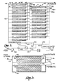
- FIG. 1 is a schematic illustration of a recirculating stages in series design for a filtration system of the prior art.
- This system is designated generally by the numeral 10 and includes four identical recirculating stages, each of which is designated generally by the numeral 12.
- Each stage 12 includes a plurality of housings or vessels 14 arranged in parallel to accommodate parallel flow of a feed stream liquid.
- Each housing contains three modules 16 which, though not so shown, are connected in series within the housing.
- a feed line 18 is connected with each of the housings 14 for directing the liquid feed stream in parallel flow through the respective housings.
- the permeate from each housing 14 is directed through an appropriate conduit (not shown) to a main permeate conveying line 20.
- the concentrate output from each housing 14 is directed to a concentrate conveying line 22 which divides into a line 24 that serves as a feed stream line for the next stage and a recirculating line 26 that is coupled with a recirculating pump 28.
- the main feed stream to system 10 is via a feed line 30 coupled with a feed pump 32 which in turn is coupled with recirculating line 26 via a line 34. It is, of course, to be understood that appropriate valves and controllers (not shown) would be utilized to complete system 10.
- the recirculating stages in series design of FIG. 1 operates by feeding liquid to be separated into permeate and concentrate fractions by introducing the liquid through feed line 30, pumps 28 and 32, and lines 34 and 18, to the multiple housings 14.
- the permeate passes radially through the individual modules 16 while the concentrate moves axially.
- a portion of the concentrate passes via lines 22 and 24 to the next stage while the remainder of the concentrate is recirculating via line 26 and pump 28 to the feed line 18.
- This system provides for improved control over pressure and flow rate (when compared with a "once through” design) as a result of the ability to vary the pressure head and volume through pumps 28 and 32.
- FIG. 1 An example of the foregoing described system is shown in FIG. 1.
- Six housings in parallel per stage are employed with three modules in series within each housing. A total of four stages are shown.
- One pump and associated valves and controllers for each of the four stages would typically be required, in addition to the pump which feeds the first stage.
- FIG. 2 the system of the present invention which is shown in FIG. 2 and designated generally by the numeral 36, this system includes two stages designated by the numerals 38 and 40.
- Stage 38 comprises a plurality of housings 14 that are disposed in parallel relationship and each contains three modules 16 connected in series within the housing.
- Each housing is fed by a supply manifold 42 having feeder lines 44 connected to the inlet of each housing.
- the permeate from the three modules 16 contained within a housing 14 is directed via a permeate line 46 to a trunk line 48 which is coupled with all of the lines 46 from the respective housings.
- each housing 14 is transported via a line 50 to a concentrate manifold 52 which is coupled with all of the lines 50 from the respective housings.
- a concentrate manifold 52 which is coupled with all of the lines 50 from the respective housings.
- Leading off of manifold 52 are a plurality of lines 54 which feed the housings 14 of the second stage 40.
- second stage 40 is identical to first stage 38 with the exception that there are two fewer housings 14 in parallel.
- the permeate trunk line of the second stage has been designated by the numeral 48a.
- the concentrate manifold for second stage 40 has been designated by the numeral 52a.
- a return line 56 extends from manifold 52a to a recirculating pump 58.
- a product outlet 60 removes that portion of the concentrate which does not move through line 56 and includes a control valve 62 for controlling the amount of concentrate leaving the system via this line.
- the output from recirculating pump 58 is moved through a connecting line 64 to supply manifold 42.
- a second control valve 62 is used to vary the amount of liquid passing through line 64.
- a feed line 66 introduces the liquid to be separated to a feed pump 68 which is connected via line 70 to recirculating pump 58.
- a third control valve 62 is located in line 70 to control the output from pump 68.
- a first flow controller C1 monitors the flow rate through valve 62 in line 70 and is connected via a control line 72 to a second controller C2 which monitors the flow through the valve 62 of line 60.
- a housing 14 is shown in cross-sectional detail. It is to be noted that for purposes of simplicity and brevity only a single module 16 is shown in the housing while in actual practice multiple modules usually are present within any one housing 14.
- a permeate pipe 74 mounted centrally through an opening in housing 14 is a permeate pipe 74 characterized by a plurality of openings 76 in the pipe wall. Wound around pipe 74 is a filtration material which may be comprised of multiple layers of a suitable membrane 78 the windings of which are separated by a membrane spacer 80 comprised of a loosely knitted inert material.
- One end of housing 14 is provided with a suitable opening (not shown) for receiving liquid feed from line 44.
- feeder line 44 may be at any place on the input side of housing 14.
- Another opening (not shown) at the outlet end of housing 14 communicates with concentrate output line 50 which connects with the concentrate manifold in the manner previously described.
- the permeate which passes through the filter media and openings 76 is collected in pipe 74 which communicates either with an adjoining permeate pipe of the next module or in the case of the final module within the connection is with permeate line 46 which delivers the permeate to a remote processing location through trunk line 48.
- a fluid feed stream containing a liquid to be separated into a concentrate fraction and a permeate fraction is delivered via feed line 66 to feed pump 68 and thence to recirculating pump 58 and supply manifold 42.
- Valves 62 are utilized to control the flow through the pumps 58 and 68 while a third valve 62 located in product outlet 60 may be used to further control the pressure within the system by limiting the amount of product which is being taken off.
- Controllers C1 and C2 monitor the flow through valves 62 in the feed line 70 and the product outlet line 60 and are designed to maintain a constant pressure flow ratio between the feed inlet 70 and outlet line 60 on opposite sides of the system.
- the third valve 62 (in line 64) allows the flow rate and pressure on the input side of the system to be controlled independently of controllers C1 and C2.
- Liquid to be separated is directed to the first stage of the filtering system 38 where the feed stream is divided and passes simultaneously in parallel flow through first stage modules 14.
- the liquid passes through filtration modules 16 in each housing 14 where the permeate passes radially through the filtering media into permeate pipe 74 and the concentrate passes axially through the filter media and out the far end of the housing.
- Permeate is collected in the trunk line 48 which carries it to a remote location for further processing. Concentrate from each housing 14 is removed via line 50 where it is directed to the concentrate manifold 52.
- the second stage 40 also has a plurality of housings 14, but fewer than the number of housings in the first stage (two fewer in the example shown). The reduction in the number of housings maintains an adequate cross-flow velocity by compensating for permeation.
- the concentrate from first stage 38 forms the feed for second stage 40 and is introduced into the second stage housings via lines 54.
- housings 14 in the second stage are also arranged for simultaneous parallel flow of the feed liquid through the housings.
- the second stage housings are, in effect, coupled in series with the corresponding housings of the first stage and further concentration of the liquid into permeate and concentrate fractions occurs in the second stage in the same manner as previously described for the first stage.
- Permeate from the second stage is delivered via lines 46 to trunk line 48a which is coupled with the first stage trunk line 48.
- Concentrate from the second stage housing 14 is directed via lines 50 to the second stage concentrate manifold 52a which divides into lines 56 and 60.
- a portion of the concentrate is removed via line 60 and directed to a remote location for further processing.
- the remaining concentrate is recirculating through line 56 and recirculating pump 58.
- a single recirculating pump 58 which is only slightly larger in flow capacity and pressure rating than recirculating pump 28 of the prior art, may be employed.
- three of the four recirculating pumps 28 shown in FIG. 1 are completely eliminated. Further savings are realized by eliminating the valves, controllers and other hardware costs which must be associated with each recirculating stage.
- the filtration system of the present invention also represents considerable operating efficiencies when compared with "once through” designs of the prior art because the utilization of recirculating pump 58 in combination with feed pump 68 provides the ability to control pressure and flow rate independently and to have a much wider operating range of flow rates and pressures than is possible with only a single pump.
- the present invention also encompasses a method of filtering a liquid into permeate and concentrate fractions which includes providing a plurality of first filtration modules disposed in side-by-side relationship for receiving a feed stream which is passed through the modules in parallel flow.
- the concentrate from the plurality of first stage modules is fed to a plurality of second stage modules which are disposed in series with the first stage modules and in parallel with each other so that the concentrate proceeds in parallel flow through the second stage modules.
- the concentrate from the second stage is partially recirculated to the first stage where it joins the initial feed stream. It is preferable to sense the liquid flow rate during both the passing of the feed stream and the recirculated steps to maintain a constant flow pressure on the system as these two steps are performed.
- the number of modules per housing and the number of housings per stage can be varied to meet the specifications for a particular filtration system. It is also to be noted that two adjacent housings 14 could be connected directly in series with the permeate pipe from one housing going directly to the permeate pipe in the next housing. The two end housings of the first stage could then have their concentrate output lines joined directly to one or more of the feed pipes for the second stage.
Landscapes
- Chemical & Material Sciences (AREA)
- Chemical Kinetics & Catalysis (AREA)
- Engineering & Computer Science (AREA)
- Water Supply & Treatment (AREA)
- Nanotechnology (AREA)
- Separation Using Semi-Permeable Membranes (AREA)
Applications Claiming Priority (2)
| Application Number | Priority Date | Filing Date | Title |
|---|---|---|---|
| US483391 | 1983-04-08 | ||
| US07/483,391 US4988445A (en) | 1990-02-22 | 1990-02-22 | Spiral wound filtration system and method of utilizing same |
Publications (1)
| Publication Number | Publication Date |
|---|---|
| EP0443257A1 true EP0443257A1 (fr) | 1991-08-28 |
Family
ID=23919868
Family Applications (1)
| Application Number | Title | Priority Date | Filing Date |
|---|---|---|---|
| EP90313686A Withdrawn EP0443257A1 (fr) | 1990-02-22 | 1990-12-14 | Dispositif de filtration enroulé en spirale et son procédé d'utilisation |
Country Status (4)
| Country | Link |
|---|---|
| US (1) | US4988445A (fr) |
| EP (1) | EP0443257A1 (fr) |
| JP (1) | JPH057739A (fr) |
| CA (1) | CA2032459A1 (fr) |
Cited By (4)
| Publication number | Priority date | Publication date | Assignee | Title |
|---|---|---|---|---|
| US7316780B1 (en) | 1999-01-29 | 2008-01-08 | Pall Corporation | Range separation devices and processes |
| WO2008096108A3 (fr) * | 2007-02-06 | 2009-05-22 | H2Oil & Gas Ltd | Système de filtration |
| US8043512B2 (en) | 2008-04-11 | 2011-10-25 | Pall Corporation | Fluid treatment arrangements and methods |
| US8048315B2 (en) | 2008-07-28 | 2011-11-01 | Pall Corporation | Fluid treatment arrangements and methods |
Families Citing this family (26)
| Publication number | Priority date | Publication date | Assignee | Title |
|---|---|---|---|---|
| US5207917A (en) * | 1991-10-08 | 1993-05-04 | Weaver Thomas J M | Recycling and recovery of aqueous cleaner solutions |
| US5470468A (en) * | 1993-10-12 | 1995-11-28 | Koch Membrane Systems, Inc. | Spiral filtration module having bypass prevention flange |
| JPH08108048A (ja) * | 1994-10-12 | 1996-04-30 | Toray Ind Inc | 逆浸透分離装置及び逆浸透分離方法 |
| CH689328A5 (de) * | 1994-10-25 | 1999-02-26 | Bucher Guyer Ag Masch | Verfahren und Vorrichtung zum Eindicken von Fest/Flüssig-Gemischen mittels Membrantechnologie. |
| US5626745A (en) * | 1994-10-27 | 1997-05-06 | Water Recycling Systems, Inc. | Waste water purification system |
| DE19520914C1 (de) * | 1995-06-08 | 1996-06-20 | Schael Wilfried | Verfahren und Vorrichtung zur Regelung einer Umkehrosmoseanlage zur Wasseraufbereitung |
| ES2193279T3 (es) * | 1995-12-13 | 2003-11-01 | Garfield Int Invest Ltd | Desalinizacion de agua. |
| US6063428A (en) * | 1996-02-26 | 2000-05-16 | The Procter & Gamble Company | Green tea extract subjected to cation exchange treatment and nanofiltration to improve clarity and color |
| WO1998024538A1 (fr) * | 1996-12-05 | 1998-06-11 | Bucher-Guyer Ag | Systeme pour la filtration membranaire dans le procede a courant transversal |
| WO1998046338A1 (fr) * | 1997-04-14 | 1998-10-22 | Nate International | Systemes de filtration modulaires et procedes |
| AU5887899A (en) * | 1998-09-17 | 2000-04-03 | Federalnoe Gosudarstvennoe Unitarnoe Predpriyatie "issledova telski Tsentr Imeni M. V. Keldysha" | Liquid filtration apparatus |
| RU2144422C1 (ru) * | 1998-09-17 | 2000-01-20 | Федеральное государственное унитарное предприятие "Исследовательский центр им. М.В.Келдыша" | Установка для фильтрации жидкости |
| US6645383B1 (en) * | 2000-08-25 | 2003-11-11 | Usf Consumer & Commercial Watergroup, Inc. | Process and apparatus for blending product liquid from different TFC membranes |
| US7285209B2 (en) * | 2001-12-28 | 2007-10-23 | Guanghua Yu | Method and apparatus for separating emulsified water from hydrocarbons |
| EP1329425A1 (fr) * | 2002-01-18 | 2003-07-23 | Toray Industries, Inc. | Procédé et appareil de dessalement |
| PT1893325T (pt) * | 2005-06-23 | 2019-02-01 | Ben Gurion Univ Of The Negev Research And Development Authority | Método de reposicionamento de elementos de escoamento numa estrutura de escoamento troncocónico |
| CN101415482B (zh) * | 2006-03-31 | 2015-04-15 | 金克克国际有限公司 | 用于化合物分离的切向流动过滤设备、系统和方法 |
| DE102009040049A1 (de) * | 2009-09-03 | 2011-03-10 | Krones Ag | Verfahren zum Regeln einer Separationsanlage mit einem Umkehrosmoseelement und Umkehrosmoseanlage |
| NL2003669C2 (en) * | 2009-10-19 | 2011-04-20 | X Flow Bv | Apparatus and process for the separation of particulate matter from a fluid. |
| JP4918126B2 (ja) * | 2009-10-27 | 2012-04-18 | 三井造船株式会社 | マニホールド構造 |
| FR2966144B1 (fr) * | 2010-10-14 | 2013-04-12 | Total Sa | Traitement de l'eau dans au moins une unite de filtration membranaire pour la recuperation assistee d'hydrocarbures |
| JP5875914B2 (ja) * | 2012-03-22 | 2016-03-02 | 三井造船株式会社 | 水処理用膜モジュールユニット |
| US10245556B2 (en) * | 2012-04-15 | 2019-04-02 | Ben Gurion University Of The Negev Research And Development Authority | Method and apparatus for effecting high recovery desalination with pressure driven membranes |
| US9517958B2 (en) * | 2014-01-30 | 2016-12-13 | Response Products Limited | System for water filtration |
| EP3512813B1 (fr) * | 2016-09-15 | 2024-11-06 | Fluence Water Israel Ltd | Système de dessalement conteneurisé |
| JP2020199477A (ja) * | 2019-06-12 | 2020-12-17 | 三浦工業株式会社 | 水処理システム |
Citations (3)
| Publication number | Priority date | Publication date | Assignee | Title |
|---|---|---|---|---|
| DE2401054A1 (de) * | 1974-01-10 | 1975-07-31 | Walter Guetling Abwasser Verfa | Verfahren und vorrichtung zum aufbereiten oelhaltiger abwaesser |
| FR2261037A1 (fr) * | 1974-02-18 | 1975-09-12 | Hitachi Ltd | |
| EP0146298A2 (fr) * | 1983-12-01 | 1985-06-26 | Exxon Research And Engineering Company | Procédé et appareil de perméation sélective à travers une membrane pour séparer l'adjuvant de filtration à partir de la cire séparée |
Family Cites Families (3)
| Publication number | Priority date | Publication date | Assignee | Title |
|---|---|---|---|---|
| US4784771A (en) * | 1987-08-03 | 1988-11-15 | Environmental Water Technology, Inc. | Method and apparatus for purifying fluids |
| US4844804A (en) * | 1988-03-18 | 1989-07-04 | Separation Dynamics, Inc. | Fluid decontamination system |
| US4850498A (en) * | 1988-03-18 | 1989-07-25 | Separation Dynamics, Inc. | Fluid decontamination system |
-
1990
- 1990-02-22 US US07/483,391 patent/US4988445A/en not_active Expired - Fee Related
- 1990-12-14 EP EP90313686A patent/EP0443257A1/fr not_active Withdrawn
- 1990-12-17 CA CA002032459A patent/CA2032459A1/fr not_active Abandoned
-
1991
- 1991-02-22 JP JP3028365A patent/JPH057739A/ja active Pending
Patent Citations (3)
| Publication number | Priority date | Publication date | Assignee | Title |
|---|---|---|---|---|
| DE2401054A1 (de) * | 1974-01-10 | 1975-07-31 | Walter Guetling Abwasser Verfa | Verfahren und vorrichtung zum aufbereiten oelhaltiger abwaesser |
| FR2261037A1 (fr) * | 1974-02-18 | 1975-09-12 | Hitachi Ltd | |
| EP0146298A2 (fr) * | 1983-12-01 | 1985-06-26 | Exxon Research And Engineering Company | Procédé et appareil de perméation sélective à travers une membrane pour séparer l'adjuvant de filtration à partir de la cire séparée |
Cited By (5)
| Publication number | Priority date | Publication date | Assignee | Title |
|---|---|---|---|---|
| US7316780B1 (en) | 1999-01-29 | 2008-01-08 | Pall Corporation | Range separation devices and processes |
| WO2008096108A3 (fr) * | 2007-02-06 | 2009-05-22 | H2Oil & Gas Ltd | Système de filtration |
| US8795527B2 (en) | 2007-02-06 | 2014-08-05 | H2Oil & Gas Ltd | Filtration system |
| US8043512B2 (en) | 2008-04-11 | 2011-10-25 | Pall Corporation | Fluid treatment arrangements and methods |
| US8048315B2 (en) | 2008-07-28 | 2011-11-01 | Pall Corporation | Fluid treatment arrangements and methods |
Also Published As
| Publication number | Publication date |
|---|---|
| JPH057739A (ja) | 1993-01-19 |
| CA2032459A1 (fr) | 1991-08-23 |
| US4988445A (en) | 1991-01-29 |
Similar Documents
| Publication | Publication Date | Title |
|---|---|---|
| US4988445A (en) | Spiral wound filtration system and method of utilizing same | |
| US12201925B2 (en) | Processes for filtering liquids using single pass tangential flow filtration systems and tangential flow filtration systems with recirculation of retentate | |
| EP0777521B1 (fr) | Appareil pour le traitement d'un liquide et methode pour la production d'un liquide separe | |
| US5599447A (en) | Manifold apparatus for tangential flow filtration apparatus | |
| US6054051A (en) | Tangential-flow filtration system | |
| JP2789548B2 (ja) | 多段膜制御装置及び方法 | |
| EP0983115B1 (fr) | Systemes de filtration modulaires | |
| CN105745009A (zh) | 单程切向流过滤系统和具有渗余物的再循环的切向流过滤系统 | |
| US20120067808A1 (en) | Filtration apparatus and process with reduced flux imbalance | |
| US20240115999A1 (en) | Osmosis modules having recirculation loops | |
| AU2002353656A1 (en) | Membrane filter housing and method of using the same | |
| CN206566772U (zh) | 一种用于多肽分级分离的膜分离装置 | |
| JP4439526B2 (ja) | 製品を完全濾過する方法とこの方法を実施する装置 | |
| EP3485962A1 (fr) | Système modulaire à membrane compacte pour la séparation de gaz | |
| KR930006396B1 (ko) | 직렬의 직교류 여과기 | |
| EP3313554B1 (fr) | Filtration par membrane haute efficacité | |
| CN223874797U (zh) | 一种膜过滤装置 | |
| WO2025157636A1 (fr) | Module de filtre, unité filtre et procédé de filtration pour séparation de gaz |
Legal Events
| Date | Code | Title | Description |
|---|---|---|---|
| PUAI | Public reference made under article 153(3) epc to a published international application that has entered the european phase |
Free format text: ORIGINAL CODE: 0009012 |
|
| AK | Designated contracting states |
Kind code of ref document: A1 Designated state(s): AT BE CH DE DK ES FR GB GR IT LI LU NL SE |
|
| 17P | Request for examination filed |
Effective date: 19920221 |
|
| 17Q | First examination report despatched |
Effective date: 19930521 |
|
| STAA | Information on the status of an ep patent application or granted ep patent |
Free format text: STATUS: THE APPLICATION IS DEEMED TO BE WITHDRAWN |
|
| 18D | Application deemed to be withdrawn |
Effective date: 19930601 |