EP0443310B1 - Appareil pour l'élimination d'ordures - Google Patents
Appareil pour l'élimination d'ordures Download PDFInfo
- Publication number
- EP0443310B1 EP0443310B1 EP91100154A EP91100154A EP0443310B1 EP 0443310 B1 EP0443310 B1 EP 0443310B1 EP 91100154 A EP91100154 A EP 91100154A EP 91100154 A EP91100154 A EP 91100154A EP 0443310 B1 EP0443310 B1 EP 0443310B1
- Authority
- EP
- European Patent Office
- Prior art keywords
- garbage
- screw
- drying
- segment
- disposer according
- Prior art date
- Legal status (The legal status is an assumption and is not a legal conclusion. Google has not performed a legal analysis and makes no representation as to the accuracy of the status listed.)
- Expired - Lifetime
Links
Images

Classifications
-
- B—PERFORMING OPERATIONS; TRANSPORTING
- B30—PRESSES
- B30B—PRESSES IN GENERAL
- B30B9/00—Presses specially adapted for particular purposes
- B30B9/02—Presses specially adapted for particular purposes for squeezing-out liquid from liquid-containing material, e.g. juice from fruits, oil from oil-containing material
- B30B9/12—Presses specially adapted for particular purposes for squeezing-out liquid from liquid-containing material, e.g. juice from fruits, oil from oil-containing material using pressing worms or screws co-operating with a permeable casing
- B30B9/128—Vertical or inclined screw presses
-
- B—PERFORMING OPERATIONS; TRANSPORTING
- B02—CRUSHING, PULVERISING, OR DISINTEGRATING; PREPARATORY TREATMENT OF GRAIN FOR MILLING
- B02C—CRUSHING, PULVERISING, OR DISINTEGRATING IN GENERAL; MILLING GRAIN
- B02C18/00—Disintegrating by knives or other cutting or tearing members which chop material into fragments
- B02C18/0084—Disintegrating by knives or other cutting or tearing members which chop material into fragments specially adapted for disintegrating garbage, waste or sewage
-
- B—PERFORMING OPERATIONS; TRANSPORTING
- B02—CRUSHING, PULVERISING, OR DISINTEGRATING; PREPARATORY TREATMENT OF GRAIN FOR MILLING
- B02C—CRUSHING, PULVERISING, OR DISINTEGRATING IN GENERAL; MILLING GRAIN
- B02C18/00—Disintegrating by knives or other cutting or tearing members which chop material into fragments
- B02C18/06—Disintegrating by knives or other cutting or tearing members which chop material into fragments with rotating knives
- B02C18/08—Disintegrating by knives or other cutting or tearing members which chop material into fragments with rotating knives within vertical containers
-
- B—PERFORMING OPERATIONS; TRANSPORTING
- B02—CRUSHING, PULVERISING, OR DISINTEGRATING; PREPARATORY TREATMENT OF GRAIN FOR MILLING
- B02C—CRUSHING, PULVERISING, OR DISINTEGRATING IN GENERAL; MILLING GRAIN
- B02C18/00—Disintegrating by knives or other cutting or tearing members which chop material into fragments
- B02C18/06—Disintegrating by knives or other cutting or tearing members which chop material into fragments with rotating knives
- B02C18/16—Details
- B02C18/18—Knives; Mountings thereof
-
- B—PERFORMING OPERATIONS; TRANSPORTING
- B02—CRUSHING, PULVERISING, OR DISINTEGRATING; PREPARATORY TREATMENT OF GRAIN FOR MILLING
- B02C—CRUSHING, PULVERISING, OR DISINTEGRATING IN GENERAL; MILLING GRAIN
- B02C18/00—Disintegrating by knives or other cutting or tearing members which chop material into fragments
- B02C18/06—Disintegrating by knives or other cutting or tearing members which chop material into fragments with rotating knives
- B02C18/16—Details
- B02C18/22—Feed or discharge means
- B02C18/2216—Discharge means
-
- B—PERFORMING OPERATIONS; TRANSPORTING
- B02—CRUSHING, PULVERISING, OR DISINTEGRATING; PREPARATORY TREATMENT OF GRAIN FOR MILLING
- B02C—CRUSHING, PULVERISING, OR DISINTEGRATING IN GENERAL; MILLING GRAIN
- B02C18/00—Disintegrating by knives or other cutting or tearing members which chop material into fragments
- B02C18/06—Disintegrating by knives or other cutting or tearing members which chop material into fragments with rotating knives
- B02C18/16—Details
- B02C18/22—Feed or discharge means
- B02C18/2225—Feed means
-
- B—PERFORMING OPERATIONS; TRANSPORTING
- B02—CRUSHING, PULVERISING, OR DISINTEGRATING; PREPARATORY TREATMENT OF GRAIN FOR MILLING
- B02C—CRUSHING, PULVERISING, OR DISINTEGRATING IN GENERAL; MILLING GRAIN
- B02C18/00—Disintegrating by knives or other cutting or tearing members which chop material into fragments
- B02C18/06—Disintegrating by knives or other cutting or tearing members which chop material into fragments with rotating knives
- B02C18/16—Details
- B02C18/24—Drives
-
- E—FIXED CONSTRUCTIONS
- E03—WATER SUPPLY; SEWERAGE
- E03C—DOMESTIC PLUMBING INSTALLATIONS FOR FRESH WATER OR WASTE WATER; SINKS
- E03C1/00—Domestic plumbing installations for fresh water or waste water; Sinks
- E03C1/12—Plumbing installations for waste water; Basins or fountains connected thereto; Sinks
- E03C1/26—Object-catching inserts or similar devices for waste pipes or outlets
- E03C1/266—Arrangement of disintegrating apparatus in waste pipes or outlets; Disintegrating apparatus specially adapted for installation in waste pipes or outlets
- E03C1/2665—Disintegrating apparatus specially adapted for installation in waste pipes or outlets
Definitions
- the present invention relates to a garbage disposer for disposal of wet garbage from a kitchen according to the generic part of claim 1.
- a garbage disposer pulverizes garbage, dries it and discharges only the resulting water into a sewage system.
- a garbage disposer is a well-known device for disposal of kitchen garbage.
- the disposer is generally attached to the drain line of a kitchen sink and adapted to comminute the garbage so that it can be discharged into a sewage system.
- a dehydrating and transporting means is disposed downwardly of a garbage crushing means and a solid-water collecting means is in turn connected to the dehydrating and transporting means (Patent Abstracts of Japan, vol. 3, no. 112 (M-73) 18 September 1979 & JP-A-54 088 669).
- a motor for driving both the garbage pulverizing means and the drying means is on top of the drying means. The motor drives a screw disposed in a dehydrating chamber.
- the screw has at runk portion and a helical blade disposed around the screw and is arranged in such a manner that a free space exists between the screen and surrounding walls of the dehydrating chamber.
- Water contained in the comminuted pieces which are fed into the dehydrating chamber passes through the filter while solid particles are urged upward by the helical blade and then transported by rotor blades at the upper portion of the screw in a solid-matter collecting chamber.
- a coagulant dripping means is disposed at the top of the solid-matter chamber. Further water is separated from the solid matter by the effect of the coagulant.
- the screw in the dehydrating chamber is uniform along its axis and the diameters of the trunk and of the blade of the screw are constant, respectively.
- the screw has no particular compression segment adapted to compress the wet particles of garbage in cooperation with any elements on the inner surface of the screen surrounding the screw.
- the present invention has been conceived and accomplished to overcome the drawbacks of the prior art garbage disposers.
- a garbage disposer coping with the above objects has the features of the characterizing part of claim 1.
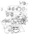
- the garbage disposer of the invention comprises a base 10, mounted thereon, a motor 7 and a garbage drying means 30 as mounted on said base, and a garbage pulverizing means 50 disposed on said motor 7.
- the garbage pulverizing means 50 comprises a crushing rotor 51, a crushing ring 52, a pair of crushing members 53, 53, a cover 54, a water seal ring 56, a check valve 57, a charging port 56, a lid 58 and a connecting ring 59.
- the crushing rotor 51 is directly mounted on an upper shaft 71 of said motor 7.
- the outside diameter of said crushing rotor 51 is slightly smaller than the outside diameter of said motor 7.
- the crushing ring 52 has an inner diameter slightly larger than the outside diameter of said crushing rotor 51.
- the internal wall of said crushing ring 52 is provided with a plurality of cutout projections 521 extending inwardly and the lower edge of the ring 52 is serrated.
- each member is generally elliptical in plan view and has a crushing projection 532 on the upper face of its forward end and an elongated groove 531 formed in the direction of its major axis at its base.
- the elongated grooves 531, 531 of these crushing members 53, 53 are engaged by pins 511, 511 secured toward the center of said crushing rotor 51 so that the crushing members 53, 53 may respectively slide in the radial direction of the crushing rotor 51.
- the aforesaid cover 54 covers the crushing rotor 51 and crushing ring 52 from above and is configured generally like a truncated cone.
- This cover 54 is rigidly secured to the upper end of a case 74 housing the motor 7 with a setscrew means through a water seal ring 55.
- a water supply port 541 formed in the peripheral wall of the cover 54 communicates with a water faucet so that the water necessary for crushing of garbage can be introduced into the cover 54 through this water supply port 541.
- the charging port 56 is communicable with a garbage discharge port of a garbage tank at the sink and its top opening 561 is provided with said lid 58 for opening and closing.
- the check valve 57 is separates the cover 54 and the charging port unit 56 from each other and is made of rubber.
- the check valve 57 is formed with a plurality of incisions 571 extending radially from its center. This check valve 57 is interposed between the top opening of the cover 54 and the charging port 56.
- the connecting ring 59 is links the cover 54 and the charging port unit 56 as a unit.
- the garbage pulverizing segment 50 is not limited to the one described above but may be similar to the crushing segment of the prior art disposer.
- the motor 7 is housed in a case 74 mounted on the base 10.
- the upper end of the case 74 is provided with an inward partitioning wall 75, forming a free space 77 between said partitioning wall 75 and the crushing rotor 51 of the garbage pulverizing segment 50.
- the upper shaft 71 of the motor 7 extends through this partitioning wall 75, while the lower shaft 76 is connected to a pulley 72 within the base through a speed reduction mechanism not shown.
- the reference numeral 60 indicates a garbage discharge port.
- This garbage discharge port 60 is disposed in the peripheral wall 73 of the case 74 housing the motor 7 in such a manner that it communicates with said free space 77 so that the garbage crushed by said garbage pulverizing segment 50 is discharged from the pulverizing segment 50 via the space 77.
- a discharge pipe 61 Connected to this garbage discharge port 60 is a discharge pipe 61 which, in turn, is connected to a feed pipe 111 on the garbage charging port 14 via a hose of PVC or the like material (not shown) as will be described hereinafter.
- the garbage drying segment 30 includes a bottom cylindrical member 1, a rotary shaft 12, a screw 3, a screen 4, a case 2 and a discharge pipe 61.
- the cylindrical bottom member 1 has a bottom wall 11 and is provided with bolt holes 161 circumferentially 90 degrees apart.
- the bottom wall 11 is centrally provided with a through-hole through which said rotary shaft 12 is passed.
- the cylindrical bottom member 1 is further provided with a garbage charging port 14 and a water discharge port 15 in parallel on its peripheral wall.
- a charging pipe 111 Connected to the garbage charging port 14 is a charging pipe 111 which, aforesaid, is connected to the discharge pipe 61 on the side of the garbage discharge port 60 via a hose of PVC or the like (not shown).
- the inner end part of the garbage charging port 14 forms a projecting orifice 17 extending into the cylindrical bottom member 1.
- Connected to the water discharge port 15 is the water discharge pipe 112 which is connected to a drain pipe of a sink or a sewage system, for instance, via a hose not shown.
- the rotary shaft 12 is disposed in such a manner that it extends out of said base 10 into said cylindrical bottom member 1.
- This rotary shaft 12 is provided with a pulley 16 at its lower end and this pulley is connected to the pulley 72 on the motor 7 side via a chain or a belt 8.
- the screw 3 cooperates with a screen 4 to dry the garbage crushed by the garbage pulverizing segment 50, and a lower portion corresponding to about one-third of its length constitutes a forced feed segment 320, while the remaining portion of the screw 3 constitutes a compression segment 321.
- This screw 3 has a helical blade 31 on the peripheral surface of its trunk portion 32.
- the trunk portion 32 is gradually increased in diameter from the lower end to the upper end.
- the helical blade 31 of the screw 3 is gradually reduced in pitch from the lower end to the upper end, and the outer diameter of the compression segment 321 is smaller than the outer diameter of the forced feed segment 320.
- this blade 31 has a plurality of anti-wear pins 33 embedded in the peripheral part of its compression segment 320.
- the screen 4 passes water selectively and is cylindrically configured.
- the inner diameter of this screen 4 is approximately equal to the outer diameter of the blade 31 at the forced feed segment 320 and the length of the screen 4 is approximately equal to the length of the screw 3.
- the lower end of the screen 4 is formed with a cutout 41 for accepting the projecting orifice 17 within the cylindrical bottom member 1, whereby the garbage is introduced into the screen 4 from below.
- the inner circumferential surface of the screen 4 which corresponds to the compression segment 321 of the screw 3 is provided with four blocking bars 42 for arresting the flow of garbage in the rotational direction of the screw 3 at equal intervals.
- the thickness of these blocking bars 42 is so designed that the peripheral surface of the blade 31 at the compression segment 321 of the screw 3 barely contacts the surface of the blocking bars 42.
- the reference numeral 5 indicates a stirring member.
- This stirring member 5 is adapted to loosen the garbage compressed and dried by said screw 3 and screen 4, and as mounted on the top of the screw 3, it revolves along with the screw 3.
- the case 2 is a cylindrical member disposed to enclose the screen 4.
- This case 2 has a diameter equal to the diameter of said bottom member 1 and is mounted on a top edge 13 of the bottom member 1 through an O-ring 113.
- This case 2 has, on the circumferential surface close to its upper edge, four stationary members 22 each having a bolt hole 21 at angular intervals of 90°.
- a deodorant can-mounting member 102 is secured to an appropriate part of the peripheral wall of the case 2.
- the discharge pipe 61 constitutes a discharge way 6 for discharging the crushed and dried garbage and its forward open end portion is downwardly curved.
- the base of this discharge pipe 61 i.e. the connection thereof to the case 2 in its upper position, is provided with a square flange 62.
- This flange 62 has bolt holes 63 at four corners. Inserted through the wall at the open end of this discharge pipe 61 is the free end of the PVC pipe 101 extending from the deodorant can 100 mounted on the mounting member 102 of the case 2.
- a bag (not shown) for collecting the dried garbage is attached to the open end portion of the discharge pipe 61 with the aid of a band 64.
- the aforementioned cylindrical bottom member 1, case 2 and discharge pipe 61 are jointed in stack by means of four elongated bolts 9 erected from within the base 10 and butterfly nuts 92 respectively threaded onto the top ends of said elongated bolts 9.
- the elongated bolts 9 pass through the bolt holes (not shown) in base 10, bolt holes 161 in bottom member 1, bolt holes 21 in case 2, and bolt holes 63 in discharge pipe 61 in succession and said butterfly nuts 92 are respectively threaded onto the top ends of these bolts.
- the reference numeral 131 indicates a chain case.
- the apparatus is supplied with electric current to start the motor 7, whereupon the crushing rotor 51 of the garbage pulverizing segment 50 and the screw 3 of the garbage drying segment 30 are simultaneously driven.
- the lid 58 of the garbage pulverizing segment 50 is then removed and the garbage is charged from the end opening 561 of the charging port unit 56, whereupon the garbage under its own weight pushes the check valve 57 and falls into the cover 54.
- the space within the cover 54 has been supplied with an appropriate amount of tap water for assisting in smooth crushing of garbage from a faucet through the water supply port 541.
- the water-containing garbage falling into the cover unit 54 is finely divided between the crushing projections 532, 532 of the crushing members 53, 53 and the cutout projections 521 of the crushing ring 52.
- the wet garbage thus comminuted enters into the free space 77 below the crushing rotor 51, from which it travels through the garbage discharge port 60, discharge pipe 61, hose (not shown), feed pipe 111 and garbage charging port 14 into the screen 4 at the projecting orifice 17.
- the wet garbage introduced into the cylindrical screen 4 is delivered upward by the revolving screw 3.
- the garbage is spirally fed upward within the screen 4 as the screw 3 revolves.
- the garbage is somewhat dried by a centrifugal force and the resulting water flows through the screen 4 into the space between the screen 4 and the case 2.
- the partially dried garbage is further pressure-fed upward by the screw 3 but when the garbage reaches the zone of the blocking bars 42 of the screen 4, it is arrested by blocking bars 42 against movement in the rotarional direction of the screw 3 and rises along the bars 42 within the screen 4.
- the garbage thus efficiently dried in the garbage drying segment 30 is loosened up by the stirring member 5 on the top of the screw 3.
- the loosened garbage travels through the discharge way 6 within the discharge pipe 61 and collects in a bag (not shown) attached to the open end of the discharge pipe 61 with the band 64.
- the dried garbage collected in the bag is discarded together with other household rubbish for disposal.
- a nozzle of the deodorant can 100 is actuated to spray the deodorant at the open end of the discharge pipe 61, whereby the malodor of the garbage is cancelled and no discomfort is felt in removing the bag from the discharge pipe 61.
Landscapes
- Engineering & Computer Science (AREA)
- Food Science & Technology (AREA)
- Environmental & Geological Engineering (AREA)
- Water Supply & Treatment (AREA)
- Hydrology & Water Resources (AREA)
- Public Health (AREA)
- Life Sciences & Earth Sciences (AREA)
- Health & Medical Sciences (AREA)
- Mechanical Engineering (AREA)
- Crushing And Pulverization Processes (AREA)
- Processing Of Solid Wastes (AREA)
- Filtration Of Liquid (AREA)
- Disintegrating Or Milling (AREA)
Claims (10)
- Dispositif d'élimination de déchets servant à désintégrer et sécher des déchets humides, qui comprend :
une base (10),
des moyens (50) de pulvérisation de déchets pour désintégrer les déchets humides,
des moyens (30) de séchage des déchets pour sécher les déchets désintégrés par lesdits moyens (50) de pulvérisation des déchets, et
un moteur (7) pour entraîner à la fois lesdits moyens (50) de pulvérisation des déchets et lesdits moyens (30) de séchage des déchets,
lesdits moyens (50) de pulvérisation des déchets et lesdits moyens (30) de séchage des déchets étant montés fixes sur ladite base (10), en étant solidaires,
dans lequel lesdits moyens (30) de séchage des déchets comprennent un élément (1) pourvu d'un fond, comportant un orifice (14) de chargement des déchets, qui communique avec lesdits moyens (50) de pulvérisation des déchets et est apte à accepter les déchets broyés humides déchargés desdits moyens (50) de pulvérisation des déchets, et un orifice (15) d'évacuation d'eau apte à évacuer l'eau produite lors du séchage des déchets,
un arbre rotatif (12) supporté, de manière à pouvoir tourner, au centre du fond dudit élément (1) pourvu d'un fond, et apte à être entraîné par ledit moteur (7),
une vis (3) comportant un corps (32) et une pale hélicoïdale (31) disposée autour dudit corps (32),
un tamis (4) disposé autour de ladite vis (3), apte à laisser passer uniquement l'eau et agencé sous la forme d'un cylindre, dont le diamètre intérieur est essentiellement égal au diamètre extérieur de ladite vis (3), et
un carter (2) disposé sur l'extérieur dudit tamis (4) moyennant la présence d'un espace intercalaire libre entre eux,
lesdits déchets admis par ledit orifice (14) d'entrée des déchets étant guidés pour pénétrer dans ledit tamis (4),
caractérisé en ce que
une partie inférieure de ladite vis, qui correspond à un tiers de sa longueur, constitue un segment d'alimentation forcée (320) apte à entraîner sous pression les déchets humides selon un déplacement ascendant, et l'autre partie de ladite vis constitue un segment de compression (321) apte à comprimer les déchets humides, le diamètre de la pale dans ledit segment de compression étant inférieur au diamètre de la pale dans ledit segment d'alimentation forcée, ledit tamis (4) comportant une pluralité de barres de blocage (42) sur sa surface intérieure circonférentielle dans la zone correspondant au segment de compression de la vis, l'épaisseur desdites barres de blocage (42) étant telle que les surfaces des barres respectives (42) sont juste en contact avec la surface périphérique de la pale (31) dans le segment de compression (321), de sorte que le déplacement des déchets dans le sens de rotation de la vis (3) est bloqué. - Dispositif d'élimination de déchets selon la revendication 1, dans lequel le corps (32) de la vis (3) a un diamètre qui augmente progressivement de son extrémité inférieure jusqu'à son extrémité supérieure.
- Dispositif d'élimination de déchets selon la revendication 2, dans lequel le pas de la pale (31) de ladite vis (3) diminue progessivement de son extrémité inférieure jusqu'à son extrémité supérieure.
- Dispositif d'élimination de déchets selon la revendication 3, dans lequel une pluralité de goupilles anti-usure (33) sont enchâssées dans la surface périphérique extérieure de la pale (31), dans le segment d'alimentation forcée de la vis.
- Dispositif d'élimination de déchets selon l'une quelconque des revendications 1, 3 et 4, qui comporte en outre un élément d'agitation (5) pour désagréger les déchets séchés, ledit élément d'agitation (5) étant disposé sur le sommet de ladite vis (3).
- Dispositif d'élimination de déchets selon la revendication 1, dans lequel lesdits moyens de séchage (30) comportent un conduit d'évacuation (61) pour évacuer les déchets qu'ils ont séchés, dans une direction prédéterminée.
- Dispositif d'élimination de déchets selon la revendication 6, dans lequel ledit conduit d'évacuation (61) est équipé d'une bande servant à fixer un sac pour recueillir les déchets évacués par ce conduit.
- Dispositif d'élimination de déchets selon la revendication 7, qui comporte en outre des moyens (102) de montage d'une bouteille de désodorisant, montés dans une position appropriée sur la surface périphérique d'un carter (2) logeant lesdits moyens (30) de séchage des déchets, une bouteille (100) remplie d'un désodorisant étant montée sur lesdits moyens de montage (102) et un tuyau (101) étant raccordé à ladite bouteille de désodorisant (100), l'extrémité libre dudit tuyau (101) étant insérée dans ledit conduit d'évacuation (61) pour que le désodorisant délivré par ladite bouteille de désodorisant désodorise les déchets séchés.
- Dispositif d'élimination de déchets selon la revendication 1, dans lequel ledit moteur (7) est disposé dans une position adjacente à et est juxtaposé auxdits moyens (30) de séchage des déchets, et lesdits moyens (50) de pulvérisation des déchets sont montés sur le sommet du moteur (7).
- Dispositif d'élimination de déchets selon la revendication 9, dans lequel ledit moteur (7) possède un arbre supérieur (71) et un arbre inférieur (76) et est monté sur la base (10) en ayant son axe orienté perpendiculairement à la base (10), et ledit arbre supérieur (71) est raccordé auxdits moyens (50) de pulvérisation des déchets, tandis que ledit arbre inférieur (76) est raccordé auxdits moyens (30) de séchage des déchets.
Applications Claiming Priority (2)
| Application Number | Priority Date | Filing Date | Title |
|---|---|---|---|
| JP2042038A JP2597021B2 (ja) | 1990-02-22 | 1990-02-22 | 生ゴミ粉砕処理装置 |
| JP42038/90 | 1990-02-22 |
Publications (3)
| Publication Number | Publication Date |
|---|---|
| EP0443310A2 EP0443310A2 (fr) | 1991-08-28 |
| EP0443310A3 EP0443310A3 (en) | 1992-03-04 |
| EP0443310B1 true EP0443310B1 (fr) | 1995-05-24 |
Family
ID=12624976
Family Applications (1)
| Application Number | Title | Priority Date | Filing Date |
|---|---|---|---|
| EP91100154A Expired - Lifetime EP0443310B1 (fr) | 1990-02-22 | 1991-01-05 | Appareil pour l'élimination d'ordures |
Country Status (6)
| Country | Link |
|---|---|
| US (1) | US5129590A (fr) |
| EP (1) | EP0443310B1 (fr) |
| JP (1) | JP2597021B2 (fr) |
| KR (1) | KR930006042B1 (fr) |
| CA (1) | CA2034575C (fr) |
| DE (1) | DE69109889T2 (fr) |
Families Citing this family (48)
| Publication number | Priority date | Publication date | Assignee | Title |
|---|---|---|---|---|
| JPH067842U (ja) * | 1992-01-30 | 1994-02-01 | 康徳 浅野 | 生ごみ処理装置 |
| DE4231293A1 (de) * | 1992-09-18 | 1994-03-24 | Dwm Maschinenbau Gmbh | Verfahren und Vorrichtung zur Behandlung von Abfallstoffen, insbesondere von organischen Gastronomieabfällen |
| US5335866A (en) * | 1993-06-24 | 1994-08-09 | Kabushiki Kaisha Nissei Giken | Waste disposer |
| US5370323A (en) * | 1993-06-24 | 1994-12-06 | Kabushiki Kaisha Nissei Giken | Waste disposer |
| US5577674A (en) * | 1993-09-08 | 1996-11-26 | Somat Corporation | Waste pulping and liquid extraction system and method including automatic bag feeding |
| JPH09503955A (ja) * | 1993-09-08 | 1997-04-22 | ソマット・コーポレーション | 廃棄物をパルプ化し液体を抽出する一体型の装置 |
| US5451004A (en) * | 1993-09-08 | 1995-09-19 | Somat Corporation | Integrated waste pulping and liquid extraction system |
| US5577673A (en) * | 1995-05-05 | 1996-11-26 | Kitchen Fresh, Inc. | Deodorized garbage disposal system |
| JPH11319790A (ja) | 1998-05-11 | 1999-11-24 | De La Concha Estrada Ernest | 生態的混合物及び廃物の除去方法 |
| KR100365896B1 (ko) * | 1999-03-05 | 2002-12-26 | 쿄코 타나카 | 음식물 쓰레기 처리장치 |
| US6439487B1 (en) | 2000-03-14 | 2002-08-27 | Emerson Electric Co. | Grinding mechanism for a food waste disposer and method of making the grinding mechanism |
| USD436496S1 (en) | 2000-03-14 | 2001-01-23 | Emerson Electric Co. | Fixed lug plate in a food waste disposer |
| US6648252B2 (en) | 2000-10-04 | 2003-11-18 | Emerson Electric Co. | Switched reluctance machine and food waste disposer employing switched reluctance machine |
| US6854673B2 (en) * | 2000-11-28 | 2005-02-15 | Emerson Electric Co. | Food waste disposer having a variable speed motor |
| US6481652B2 (en) | 2000-11-28 | 2002-11-19 | Emerson Electric Co. | Food waste disposer having variable speed motor and methods of operating same |
| KR20020023988A (ko) * | 2002-01-03 | 2002-03-29 | 김형호 | 음식물 쓰레기의 분쇄장치 |
| JP2006510486A (ja) * | 2002-12-03 | 2006-03-30 | ドンギャク チョイ | 生ゴミ処理装置 |
| US20040173697A1 (en) * | 2003-03-07 | 2004-09-09 | Emerson Electric Co. | Food waste reduction mechanism for disposer |
| US7607599B2 (en) * | 2003-06-06 | 2009-10-27 | Emerson Electric Co. | Food waste reduction mechanism for disposer |
| JP4063836B2 (ja) * | 2005-02-01 | 2008-03-19 | キ キム ヤン | 厨芥処理装置 |
| KR100638372B1 (ko) * | 2005-02-01 | 2006-10-25 | 김영기 | 음식물쓰레기 처리장치 |
| WO2009063265A1 (fr) * | 2007-11-16 | 2009-05-22 | Texa S.R.L. | Appareil et procédé de broyage de déchets alimentaires |
| CN101628251B (zh) * | 2008-07-17 | 2012-12-05 | 德昌电机(深圳)有限公司 | 食品垃圾处理装置 |
| US8100352B2 (en) * | 2009-12-21 | 2012-01-24 | Whirlpool Corporation | Under-sink waste processing appliance |
| US9499963B2 (en) | 2009-12-21 | 2016-11-22 | Whirlpool Corporation | Under-sink waste processing appliance |
| KR101670750B1 (ko) * | 2014-06-30 | 2016-10-31 | 엘지전자 주식회사 | 음식물 처리장치의 제어방법 |
| DE202014104522U1 (de) | 2014-09-22 | 2016-01-04 | Viega Gmbh & Co. Kg | Ablaufgarnitur für eine Spüle, insbesondere Küchenspüle |
| CN104385660A (zh) * | 2014-10-11 | 2015-03-04 | 重庆市涪陵区松泽环保科技有限公司 | 螺旋压榨脱水机在餐厨垃圾处理中的应用 |
| US10118358B2 (en) * | 2014-12-22 | 2018-11-06 | Us Farm Systems, Inc. | Screw press for separation of liquid from bulk materials |
| US9694362B2 (en) | 2015-06-18 | 2017-07-04 | David Paul Lang | Composting garbage disposal |
| CN105710109A (zh) * | 2016-02-15 | 2016-06-29 | 上海恒霞环保设备有限公司 | 湿垃圾源头减量处理系统站 |
| CN106040706A (zh) * | 2016-06-30 | 2016-10-26 | 苏州香山红叶环境技术有限公司 | 商用型餐厨垃圾处理机 |
| CN106140392B (zh) * | 2016-08-24 | 2018-08-07 | 广东轻工职业技术学院 | 一种餐厨垃圾用的粉碎烘干处理装置 |
| CN107552130B (zh) * | 2017-10-27 | 2019-06-14 | 南通海睿知新信息科技有限公司 | 一种医疗垃圾用高效粉碎设备 |
| CN107716076A (zh) * | 2017-11-01 | 2018-02-23 | 宁波市江北区伊人宝贸易有限公司 | 一种建筑用废瓷砖高效破碎装置 |
| CN108160185A (zh) * | 2017-11-20 | 2018-06-15 | 长沙双合盛企业管理有限公司 | 一种方便出料的建筑用凝结水泥块粉碎设备 |
| CN108246778B (zh) * | 2018-03-05 | 2023-08-29 | 上海恒霞环保设备有限公司 | 一种湿垃圾源头减量资源化处置系统 |
| CN110772858B (zh) * | 2019-10-11 | 2022-02-18 | 孙雨飞 | 一种采油井热洗液过滤装置 |
| KR102352180B1 (ko) * | 2020-03-26 | 2022-01-17 | 김윤옥 | 음식물 쓰레기 처리장치 |
| CN111305332B (zh) * | 2020-04-26 | 2021-05-18 | 简胜坚 | 一种家用垃圾粉碎压缩机 |
| CN113926550B (zh) * | 2020-07-13 | 2022-12-13 | 宁波方太厨具有限公司 | 一种垃圾处理器 |
| AU2021308882A1 (en) | 2020-07-13 | 2023-02-09 | BORA - Vertriebs GmbH & Co KG | Rinsing channel device for a basin |
| CN111746980B (zh) * | 2020-07-15 | 2022-07-08 | 中国人民解放军陆军军医大学第一附属医院 | 一种医疗垃圾收集装置 |
| CN111729384B (zh) * | 2020-07-31 | 2021-11-02 | 湖南云凯环保工程有限公司 | 一种环保型污水处理装置 |
| CN112517177A (zh) * | 2020-10-30 | 2021-03-19 | 浙江松华新材股份有限公司 | 一种工程塑料粉碎机 |
| CN112875842A (zh) * | 2021-02-12 | 2021-06-01 | 林臣鑫 | 一种污水处理装置 |
| EP4367335A1 (fr) | 2021-07-09 | 2024-05-15 | Pflieger Solutions UG (Haftungsbeschraenkt) | Dispositif d'évacuation et procédé de filtration et d'évacuation de solides d'un liquide |
| WO2024149744A1 (fr) | 2023-01-09 | 2024-07-18 | Pflieger Solutions Gmbh | Dispositif d'évacuation et procédé de filtration et d'évacuation de solides d'un liquide |
Family Cites Families (14)
| Publication number | Priority date | Publication date | Assignee | Title |
|---|---|---|---|---|
| CA793823A (en) * | 1968-09-03 | C. R. Shepherd Thomas | Waste disposal apparatus | |
| GB667594A (en) * | 1950-01-18 | 1952-03-05 | William Warren Triggs | Centrifugal bowl filter |
| US2970776A (en) * | 1957-06-27 | 1961-02-07 | Meili & Worthington Inc | Waste disintegrating machines |
| US3188942A (en) * | 1962-12-05 | 1965-06-15 | Somat Corp | Apparatus for disintegrating and dewatering fibrous material |
| US3319897A (en) * | 1964-09-08 | 1967-05-16 | Somat Corp | Waste disposal unit |
| GB1200842A (en) * | 1968-02-29 | 1970-08-05 | Howard Walter Dyson | Apparatus for disintegrating solid materials |
| US3527158A (en) * | 1968-06-20 | 1970-09-08 | William O Young | Positive displacement press |
| JPS55109454A (en) * | 1979-02-17 | 1980-08-22 | Tokyo Shibaura Electric Co | Garbage disposal machine |
| JPS5946669A (ja) * | 1982-09-09 | 1984-03-16 | Nec Corp | 閃光装置 |
| DE3411918A1 (de) * | 1984-03-30 | 1985-10-10 | Meiko Maschinen- Und Apparatebau, Ingenieur Oskar Meier Gmbh & Co, 7600 Offenburg | Maschine zum zerkleinern und verdichten von abfall |
| US4582261A (en) * | 1984-05-18 | 1986-04-15 | Adamation | Pulper |
| JPS63126695A (ja) * | 1986-11-14 | 1988-05-30 | Tago Kiyoutarou | 生ごみ処理装置 |
| JPS63258656A (ja) * | 1987-04-15 | 1988-10-26 | 日空工業株式会社 | 厨芥処理装置 |
| US4881690A (en) * | 1988-01-28 | 1989-11-21 | Liangtraco (Aust) Pty. Ltd. | Waste comminuting apparatus |
-
1990
- 1990-02-22 JP JP2042038A patent/JP2597021B2/ja not_active Expired - Lifetime
-
1991
- 1991-01-04 US US07/637,573 patent/US5129590A/en not_active Expired - Fee Related
- 1991-01-05 EP EP91100154A patent/EP0443310B1/fr not_active Expired - Lifetime
- 1991-01-05 DE DE69109889T patent/DE69109889T2/de not_active Expired - Fee Related
- 1991-01-18 CA CA002034575A patent/CA2034575C/fr not_active Expired - Fee Related
- 1991-02-02 KR KR1019910001813A patent/KR930006042B1/ko not_active Expired - Fee Related
Also Published As
| Publication number | Publication date |
|---|---|
| CA2034575C (fr) | 1996-10-01 |
| KR910021261A (ko) | 1991-12-20 |
| JP2597021B2 (ja) | 1997-04-02 |
| US5129590A (en) | 1992-07-14 |
| DE69109889D1 (de) | 1995-06-29 |
| EP0443310A2 (fr) | 1991-08-28 |
| DE69109889T2 (de) | 1995-12-21 |
| JPH03245855A (ja) | 1991-11-01 |
| CA2034575A1 (fr) | 1991-08-23 |
| KR930006042B1 (ko) | 1993-07-03 |
| EP0443310A3 (en) | 1992-03-04 |
Similar Documents
| Publication | Publication Date | Title |
|---|---|---|
| EP0443310B1 (fr) | Appareil pour l'élimination d'ordures | |
| US7086405B1 (en) | Screenings washer | |
| CN101811126A (zh) | 一种具有传送转子的传送装置和使用该装置的食品废物处理设备 | |
| US2836369A (en) | Food waste grinder | |
| US3165270A (en) | Garbage disposer | |
| KR20020026143A (ko) | 싱크대에 설치되는 음식물 쓰레기 처리 장치 | |
| US2715735A (en) | Grinding unit for disposal devices | |
| JPH03110099A (ja) | 生ゴミ処理装置 | |
| KR102186398B1 (ko) | 음식물 감량장치 | |
| KR102070921B1 (ko) | 분쇄장치 및 이를 포함하는 음식물 처리장치 | |
| US1898243A (en) | Means for disposing of garbage | |
| KR20020070737A (ko) | 싱크대용 음식물찌거기 분리장치 | |
| KR100378638B1 (ko) | 싱크대용 음식물찌거기 분리장치 | |
| KR20220028713A (ko) | 폐음식물용 파쇄기 | |
| JPH0238260B2 (fr) | ||
| JPH1133789A (ja) | 生ゴミ粉砕処理装置 | |
| KR200235662Y1 (ko) | 싱크대용 음식물찌거기 분리장치 | |
| KR200243674Y1 (ko) | 싱크대용 음식물찌거기 처리장치 | |
| KR200229479Y1 (ko) | 싱크대용 음식물찌거기 분리장치 | |
| KR20040019756A (ko) | 음식쓰레기 처리장치 | |
| KR20080040223A (ko) | 음식물 쓰레기 처리장치 | |
| KR200215055Y1 (ko) | 싱크대에 설치되는 음식물 쓰레기 처리 장치 | |
| KR19990025319A (ko) | 음식물 쓰레기 분쇄 처리장치 | |
| KR20190022254A (ko) | 소형 음식물 쓰레기용 분쇄장치 | |
| KR200271428Y1 (ko) | 음식물 쓰레기의 분쇄장치 |
Legal Events
| Date | Code | Title | Description |
|---|---|---|---|
| PUAI | Public reference made under article 153(3) epc to a published international application that has entered the european phase |
Free format text: ORIGINAL CODE: 0009012 |
|
| AK | Designated contracting states |
Kind code of ref document: A2 Designated state(s): DE FR GB IT NL |
|
| PUAL | Search report despatched |
Free format text: ORIGINAL CODE: 0009013 |
|
| AK | Designated contracting states |
Kind code of ref document: A3 Designated state(s): DE FR GB IT NL |
|
| 17P | Request for examination filed |
Effective date: 19920828 |
|
| 17Q | First examination report despatched |
Effective date: 19930624 |
|
| GRAA | (expected) grant |
Free format text: ORIGINAL CODE: 0009210 |
|
| AK | Designated contracting states |
Kind code of ref document: B1 Designated state(s): DE FR GB IT NL |
|
| REF | Corresponds to: |
Ref document number: 69109889 Country of ref document: DE Date of ref document: 19950629 |
|
| ITF | It: translation for a ep patent filed | ||
| ET | Fr: translation filed | ||
| PLBE | No opposition filed within time limit |
Free format text: ORIGINAL CODE: 0009261 |
|
| 26N | No opposition filed | ||
| K2C3 | Correction of patent specification (complete document) published |
Effective date: 19950524 |
|
| PGFP | Annual fee paid to national office [announced via postgrant information from national office to epo] |
Ref country code: FR Payment date: 19971217 Year of fee payment: 8 |
|
| PGFP | Annual fee paid to national office [announced via postgrant information from national office to epo] |
Ref country code: GB Payment date: 19971218 Year of fee payment: 8 |
|
| PGFP | Annual fee paid to national office [announced via postgrant information from national office to epo] |
Ref country code: DE Payment date: 19980129 Year of fee payment: 8 |
|
| PGFP | Annual fee paid to national office [announced via postgrant information from national office to epo] |
Ref country code: NL Payment date: 19980130 Year of fee payment: 8 |
|
| PG25 | Lapsed in a contracting state [announced via postgrant information from national office to epo] |
Ref country code: GB Free format text: LAPSE BECAUSE OF NON-PAYMENT OF DUE FEES Effective date: 19990105 |
|
| PG25 | Lapsed in a contracting state [announced via postgrant information from national office to epo] |
Ref country code: NL Free format text: LAPSE BECAUSE OF NON-PAYMENT OF DUE FEES Effective date: 19990801 |
|
| GBPC | Gb: european patent ceased through non-payment of renewal fee |
Effective date: 19990105 |
|
| PG25 | Lapsed in a contracting state [announced via postgrant information from national office to epo] |
Ref country code: FR Free format text: LAPSE BECAUSE OF NON-PAYMENT OF DUE FEES Effective date: 19990930 |
|
| PG25 | Lapsed in a contracting state [announced via postgrant information from national office to epo] |
Ref country code: DE Free format text: LAPSE BECAUSE OF NON-PAYMENT OF DUE FEES Effective date: 19991103 |
|
| REG | Reference to a national code |
Ref country code: FR Ref legal event code: ST |
|
| PG25 | Lapsed in a contracting state [announced via postgrant information from national office to epo] |
Ref country code: IT Free format text: LAPSE BECAUSE OF NON-PAYMENT OF DUE FEES Effective date: 20050105 |